PAGE 10 44124-0798 <90-00024>
CHECKOUT
Use the following equipment to test the 44124 DCTM:
♦A Dantel A15-00440-00 56-pin extender card or equivalent.
♦A Hewlett-Packard 3551 or equivalent voice frequency gen-
erator.
♦Test cables.
1. Mount the 44124 DCTM into the extender card.
1. Plug the card into the appropriately wired slot.
2. Set all the gain and equalization switches to OFF.
2. Use the transmission test set to record cable losses.
1. Have the distant end transmit a tone at a level of 0 dBmO.
2. Use the transmission test set programmed for bridged input level
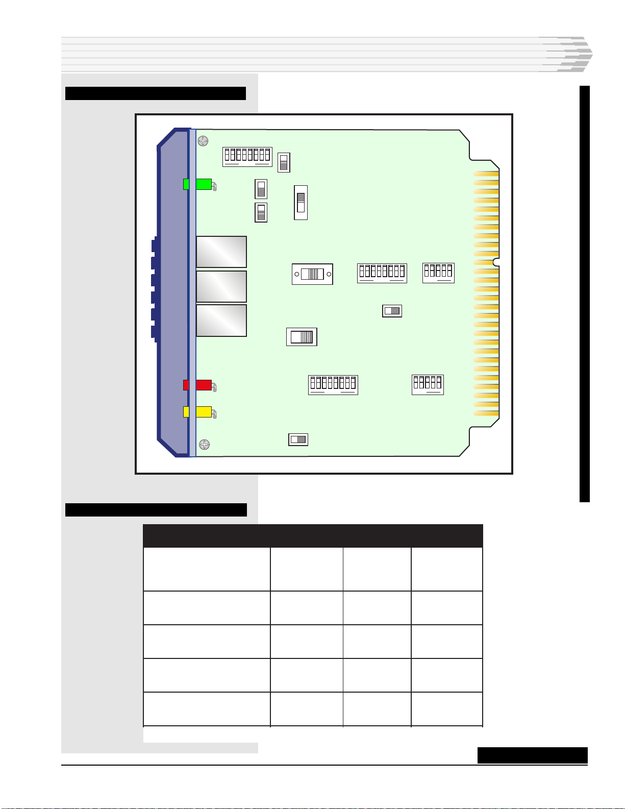
measurement. Insert the test cord into the RCV MON jack (refer to
Fig. 5 for a 44124 DCTM front panel view). Record the cable losses
(in dB) at the receive line end for the 404 Hz, 1004 Hz, 2504 Hz,
and 3204 Hz frequencies.
3. Determine measurements and set switches.
1. Determine the difference (in dB) between cable loss measurements
at 404 Hz and 1004 Hz (the LF slope of the cable).
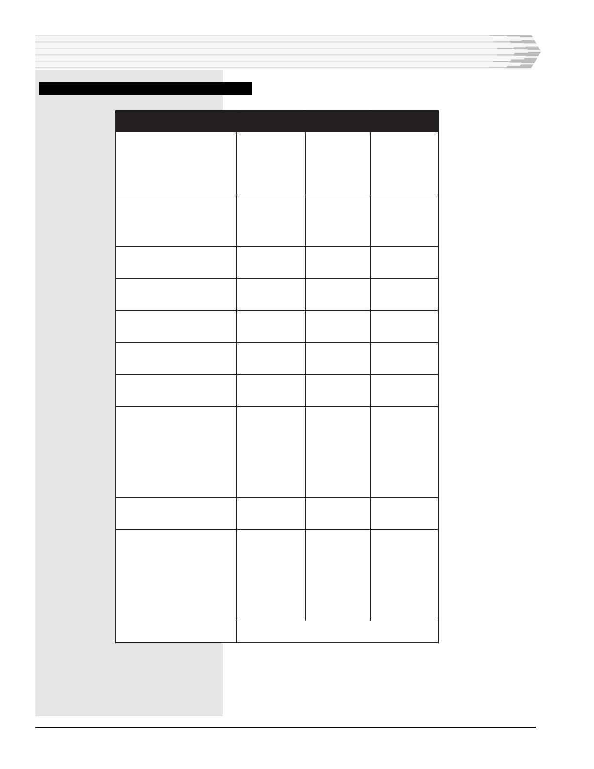
If the LF slope is equal to or greater than 3.0 dB, set S8-1 ON
(nonloaded cable). Set LF slope (SL) settings of switches S8-2 to
S8-5 using the Nonloaded Cable column of Table B.
If the LF slope is less than 3.0 dB, set S8-1 to OFF (loaded cable).
Set LF slope (SL) settings of switches S8-2 to S8-5 using the
Loaded Cable column of Table B.
2. Determine the difference (in dB) between cable loss measurements
at 1004 Hz and 3204 Hz (the height for the cable).
3. Set height with switches S7-1 to S7-4. Refer to Table C.
4. Determine the difference (in dB) between cable loss measurements
at 1004 Hz and 2504 Hz (the difference of the cable).
5. Set bandwidth with switches S7-5 to S7-8. Refer to Tables D and E.
4. Set gain or loss.
1. Set the input (receive) gain or loss as follows (Refer to Table A and
Fig. 3):
• Set the level meter to 600 ohms.
• Plug the test cord into the RCV OUT jack (Refer to Fig. 5).
• Have the far end transmit a 1004 Hz tone at 0 dBmO.
• Set switch S13 for gain or loss.
FIG. 5 - FRONT PANEL VIEW
INSTALLATION
CONTINUED . . .
B11-44124-00 REV__
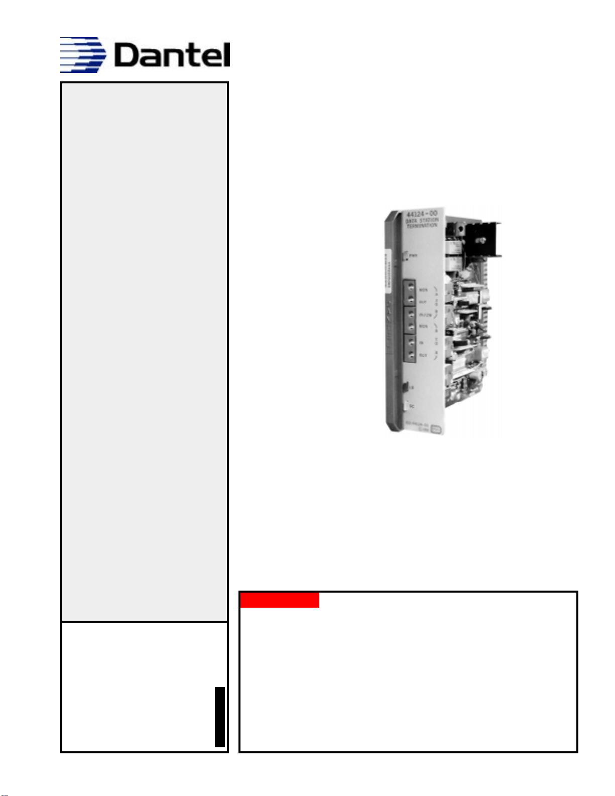
44124-00
DATA STATION
TERMINATION
PWR
LB
SC
MON
OUT
IN/2W
MON
IN
OUT
A
T
O
B
B
T
O
A