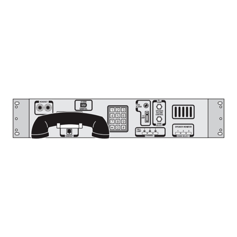
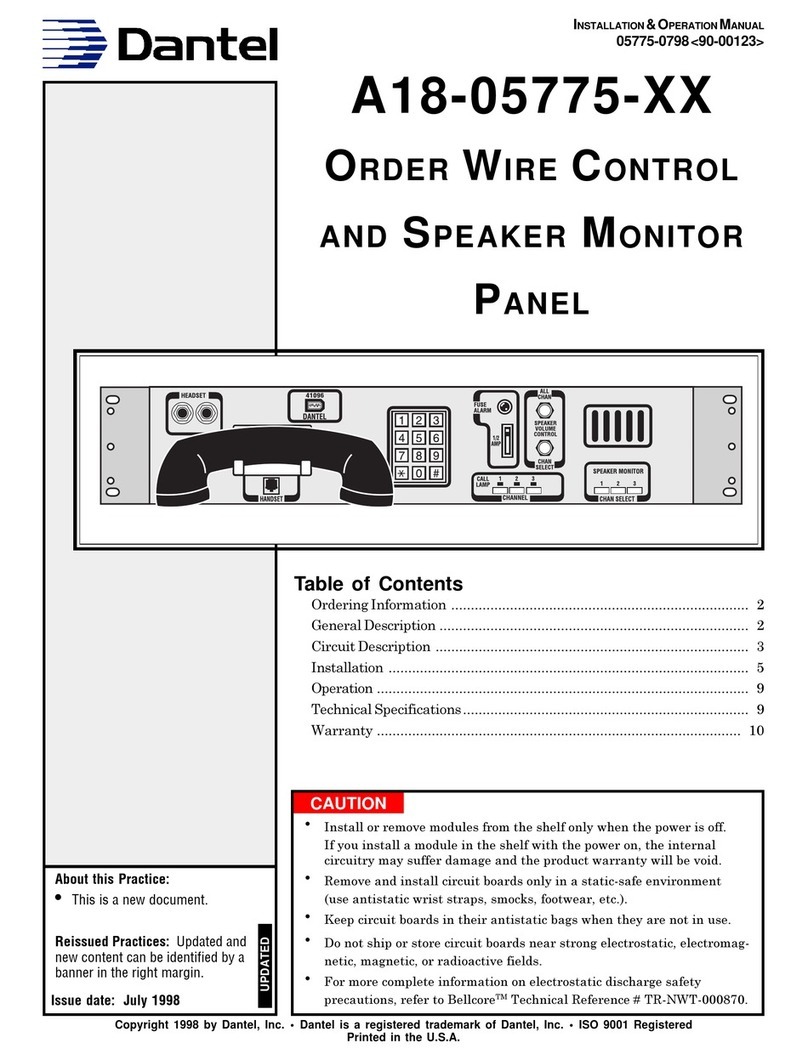
Dantel 41095 User manual

CAUTION
•Install or remove modules from the shelf only when the power is off.
If you install a module in the shelf with the power on, the internal
circuitry may suffer damage and the product warranty will be void.
•Remove and install circuit boards only in a static-safe environment
(use antistatic wrist straps, smocks, footwear, etc.).
•Keep circuit boards in their antistatic bags when they are not in use.
•Do not ship or store circuit boards near strong electrostatic, electromag-
netic, magnetic, or radioactive fields.
•For more complete information on electrostatic discharge safety
precautions, refer to BellcoreTM Technical Reference # TR-NWT-000870.
Copyright 1998 by Dantel, Inc. • Dantel is a registered trademark of Dantel, Inc. • ISO 9001 Registered
Printed in the U.S.A.
INSTALLATION & OPERATION MANUAL
41095-0898 <90-00129>
41095
ORDER WIRE CONTROL AND
SPEAKER MONITOR PANELS
About this Practice:
This practice has been reissued to:
• Incorporate all addendums.
Issue date: August 1998
Reissued Practices: Updated and
new content can be identified by a
banner in the right margin.
UPDATED
Table of Contents
Ordering Information ........................................................................... 2
General Description.............................................................................. 2
Circuit Description ............................................................................... 3
Installation............................................................................................ 6
Operation ............................................................................................ 10
Technical Specifications ..................................................................... 11
Warranty ............................................................................................. 12
1 2 3 4 5 6
CHANNEL SELECT
CALL LAMP
HEADSET
1
2
A
M
P
_
FA2
1
2
A
M
P
_
FA1
SPK 1 SPK 2
VOLUME
CONTROL
1 2 3 4 5 6
SPEAKER 2 MONITOR SELECT
2 31
564
8 97
0#
*
ABC DEF
GHI JKL MNO
PRS TUV WXY
OPER

PAGE 2 41095-0898 <90-00129>
ORDERING INFORMATION
NOTE: This section lists the different options available for this product. To order any of the avail-
able options, contact Dantel Inside Sales through our toll-free number, 1-800-432-6835.
OPTION NUMBER FEATURES
B13-41095-10 Six-Circuit Monitor/Control Panel w/ Audible Signaling
C13-41095-01 12-Circuit Monitor/Control Panel
GENERAL DESCRIPTION
The Dantel 41095 Order Wire Control and Speaker Monitor
Panel (41095 Panel) provides centralized monitoring facili-
ties for six or twelve selective signaling order wire terminals.
You can use the 41095 Panel to orginate a call or answer an
incoming call on an individual order wire channel.
The 41095 Panel mounts in an EIA standard 19” rack next to or
near the order wire terminal. The 41095 Panel occupies 5¼” of
vertical rack space and operates from -21 to -56 VDC power.
The 41095 Panel consists of a monitor section and a control
section. The monitor section includes:
♦A push-button channel selector
♦Two speaker with amplifiers
♦Two volume controls
♦A fuse
♦A fuse alarm LED
The monitor section provides monitoring of all associated order
wire channels over one of the speakers. The other speaker can
monitor one channel (41095-10) or two channels (41095-01).
The control section includes:
♦A push-button channel selector
♦DTMF dial
♦Handset
♦Handset cradle
♦Headset jacks
The control section originates a call or answers an incoming call
on an individual order wire channels.

41095-0898 <90-00129> PAGE 3
CIRCUIT DESCRIPTION
Fig. 1 shows a 41095 Panel block diagram.
FIG. 1 - BLOCK DIAGRAM, 41095
D9
3 R1 1 3 R2 1
D10
B C D O E F
SP1
1
2
22
I
J
SP1
1
2
L
K
N
M
G
A
H
1F1 2
1F2 2
3
3
MONITOR SELECT
ASSY.
J101/P101
1
2
3
4
5
6
7
8
9
10
11
12
1
3
TB1
STA 1
STA 2
STA 3
STA 4
STA 5
STA 6
To each Order Wire
Terminal
Odd to P1-12
Even to P1-7
P103 P102
3
4
5
6
7
8
9
10
11
12
STA 7
STA 8
STA 9
STA 10
STA 11
STA 12
To each Order Wire
Terminal
Odd to P1-12
Even to P1-7
1
2
-BATT
GND
1 2 3 2 3 4 5 6 7 8
1 2 3 2 3 4 5 6 7 8
J103 J102
Option
Monitor Select Sub-Assy
P103 P102
J107/P107
DIAL
P104
J1
J2
S/W
R/G
1
2
3
4
4
1
4
1
1
2
3
1
2
3
4
5
6
J105
J106
Hookswitch
(Shown Off-Hook)
Handset Jack
TYP
STA 1 THRU 12
TYP
J1 THRU J18
RCV
XMT
LED
STA Select
TB2TB3
1A
THRU
10 F
1A
THRU
8 F
1 2 3 4
J104
A
B
Fig. 2 shows the 41095 Order-Wire and Speaker Monitor Panel
functional schematic.
The 41095 Panel monitoring section monitors all associated
order wire channels over the speaker. Incoming calls couple
through transformers to operational amplifiers, and a volume
control potentiometer to feed speaker amplifiers.
The push-button speaker monitor channel selector monitors any
one or two channels through an additional volume control
potentiometer. You can monitor the selected channel(s) at a
louder level and monitor unselected channels over the speaker
at a quieter level.
A fuse and fuse alarm indicator LED are on the front panel.
When the fuse blows, the alarm indicator LED lights up.

PAGE 4 41095-0898 <90-00129>
FIG. 2 - SCHEMATIC, MONITOR SELECT, 41095
MONITOR SELECT SCHEMATIC
S1
GND
-21 TO -56 VDC
1
2
3
S2
S3
S4
S5
S6
P102
8
7
6
5
4
3
2
Volume
R1
(TB-1)
P101 / J101
TYP
-10db
T 1
R 2
3
4
5
6
7
8
9
10
11
12
SPK - 1
SPK - 2
TO OPTION
MONITOR
SELECT
SUBASSEMBLY
(Refer to Fig. 1)
Volume
R2
The control section originates a call or answers an incoming call
on an individual order wire channel. A flashing LED above the
channel button indicates an incoming call. (The order wire
terminal provides an audible indication.) Pressing the channel
button connects the handset to the respective order wire chan-
nel. You can use a headset instead of the handset.
Fig. 3 shows the 41095 Panel channel select schematic for wiring
six order wire terminals (41095-10) or twelve order wire termi-
nals (41095-01).
CIRCUIT DESCRIPTION

41095-0898 <90-00129> PAGE 5
FIG. 3 - SCHEMATIC, CHANNEL SELECT, 41095
CIRCUIT DESCRIPTION
S1
P104
1
2
3
4
XMT R
RCV R
RCV T
XMT T
1A
J1 RCV R
2A
J2 RCV R
CHANNEL 1
1D
J1 LAMP (-)
1C
J1 LAMP (+)
S7
S8
S9
S10
S11
S12
7A
J7 RCV R CHANNEL 7
7D
J7 LAMP (-)
7C
J7 LAMP (+)
8A
J8 RCV R CHANNEL 8
8D
J8 LAMP (-)
8C
J8 LAMP (+)
9A
J9 RCV R CHANNEL 9
9D
J9 LAMP (-)
9C
J9 LAMP (+)
10A
J10 RCV R CHANNEL 10
10D
J10 LAMP (-)
10C
J10 LAMP (+)
11A
J11 RCV R CHANNEL 11
11D
J11 LAMP (-)
11C
J11 LAMP (+)
12A
J12 RCV R
CHANNEL 12
12D
J12 LAMP (-)
12C
J12 LAMP (+)
10E
J10 XMT R
10F
J10 RCV T
10B
J10 XMT T
11F
J11 RCV T
11B
J11 XMT T
12E
J12 XMT R
12F
J12 RCV T
12B
J12 XMT T
11E
J11 XMT R
5A
J5 RCV R
CHANNEL 5
5D
J5 LAMP (-)
5C
J5 LAMP (+)
6A
J6 RCV R CHANNEL 6
6D
J6 LAMP (-)
6C
J6 LAMP (+)
3A
J3 RCV R CHANNEL 3
3D
J3 LAMP (-)
3C
J3 LAMP (+)
4A
J4 RCV R CHANNEL 4
4D
J4 LAMP (-)
4C
J4 LAMP (+)
CHANNEL 2
2D
J2 LAMP (-)
2C
J2 LAMP (+)
6 STATION
R1
D1
R2
D2
R3
D3
R4
D4
R5
D5
R6
D6
R8
D8
R9
D9
R10
D10
R11
D11
R12
D12
12 STATION
S6
S5
S4
S3
S2
R7
D7
1E
J1 XMT R
1F
J1 RCV T
1B
J1 XMT T
2E
J2 XMT R
2F
J2 RCV T
2B
J2 XMT T
3E
J3 XMT R
3F
J3 RCV T
3B
J3 XMT T
4E
J4 XMT R
4F
J4 RCV T
4B
J4 XMT T
5E
J5 XMT R
5F
J5 RCV T
5B
J5 XMT T
6E
J6 XMT R
6F
J6 RCV T
6B
J6 XMT T
7E
J7 XMT R
7F
J7 RCV T
7B
J7 XMT T
8E
J8 XMT R
8F
J8 RCV T
8B
J8 XMT T
9E
J9 XMT R
9F
J9 RCV T
9B
J9 XMT T

PAGE 6 41095-0898 <90-00129>
INSTALLATION
Installation consists of wiring a jumper for modular cords,
connecting the speaker leads, connecting power, connecting
signaling leads, and wiring to the DTSS3A order wire terminal.
1. Wire the Modular Cords Jumper.
Refer to Fig. 4. A board behind the panel provides modular-type
telephone jacks, labeled J1 through J12. Each order wire tele-
phone jack connects to one of the jacks (J1-J12) using a six-lead
extension phone cord. These jacks carry the four-wire signal
leads and the lamp leads.
When you use the modular cords, you must install a jumper on
each order wire terminal from pin P3-1 to pin P1-5 and from pin
P3-2 to pin P1-7.
Use wire-wrap terminal blocks (TB2 and TB3) when you do not
use modular-type cords.
2. Connect Speaker Leads.
Refer to Fig. 4 and Fig. 6. Separate wire-wrap terminals (J101,
J107 and J108) are available to hook up the speaker lines from
the DTSS3A terminals.
3. Connect Power.
Refer to Fig. 4. Power (-21 to -56 VDC) connects at screw termi-
nal strip TB1.
4. Connect Signaling Leads.
For a six-circuit 41095 Panel (41095-10) connect signaling leads
from any of the pins at TB2-9 (A-E) or TB2-10 (A-E) to pin P1-1
on each order wire terminal. Jumper pins P1-2 to P1-6 on each
order wire. Refer to Table A and Fig. 5.
5. Wire to the DTSS3A terminal.
Wire the 41095 Panel to the DTSS3A with modular cords or
wire-wrap connections. Refer to Fig. 6.

41095-0898 <90-00129> PAGE 7
FIG. 4 - CONTROL AND JACK LOCATIONS AND DIMENSIONS
J1 J3 J5 J7 J9 J11
Bracket Position
for 23" mounting
321
TB1
J101, J107, J108
AUDIBLE
SIGNALING
MODULE
TB2 REAR
HEADSET
123
65
4
789
#
0
*
123456
CIRCUIT
VOLUME
CONTROL
SPK 1 SPK 2
SPEAKER 2 MONITOR SELECT
CHANNEL SELECT
123456
CALL LAMP
F
U
S
E
F
U
S
E
41095
1 6
HANDSET
12
FA1 FA2
17.00" (SHOWN WITH COVER REMOVED)
TOP VIEW
5.00"
6.00"
5.25"
19.00"
FRONT VIEW
REAR VIEW SHOWING TERMINAL LOCATIONS
12
12
12
123
J108 J107 J101 TB1 -BATT GND
A
B
C
D
E
F
A
B
C
D
E
F
1 2 3 4 5 6 7 8 9 10 1 2 3 4 5 6 7 8 9 10
TB2 TB3
J1 THROUGH J12
J2 J4 J6 J8 J10 J12
1
1
1
INSTALLATION

PAGE 8 41095-0898 <90-00129>
FIG. 5 - SIGNALING FUNCTION WIRING
1 2 3 4 5 6 7 8 9 10
A
B
C
D
E
F
USE 9 A-E, 10 A-E
DO NOT USE 9 AND 10 F
41095 -1X
REAR VIEW
Optional
wiring scheme
1 2 3 4 5 6 7 8 9 10 11 12 13 14 15 16 17
P1
Order Wire
Terminal No. 1
J2
1 2 3 4 5 6 7 8 9 10 11 12 13 14 15 16 17
P1
Order Wire
Terminal No. 6
J2
Order-wire
Terminal No. 2
Order-wire
Terminal No. 3
Order-wire
Terminal No. 4
Order-wire
Terminal No. 5
Wiring the 41095 signaling function
INSTALLATION

41095-0898 <90-00129> PAGE 9
FIG. 6 - WIRING TO DTSS3A USING MODULAR CORDS AND WIRE-WRAP CONNECTIONS
15
A
B
C
D
E
F
1 2 3 4 5 6 7 8 9 10
1 2 3 4 5 6 7 8 9 10
TB2 TB2
J101
12
1
A
B
C
D
E
F
1 2 3 4 5 6 7 8 9 10
1 2 3 4 5 6 7 8 9 10
TB2 TB2
J101
12
P1
1
12
1 2 3 4 5 6 7 8 9 10 11 12 13 14151617
J1
J1 J2
P1
12
J1 J2
P3
P3 1 2 3 4 5 6 7 8 9 10 111213 141516 17
Telephone Jack
Wiring the 41095 to the DTSS3A Using Wire-Wrap Connections
(Signaling Wiring not shown)
Wiring the 41095 to the DTSS3A Using Modular Cords
(Signaling Wiring not shown)
INSTALLATION

PAGE 10 41095-0898 <90-00129>
TABLE A - CHANNEL CONNECTIONS
ORDER WIRE TERMINAL CONNECTIONS
Each
Order Wire P1-9 P1-10 P1-7 P1-5 P1-11 P1-8 P1-12 P1-7 --
TO:
SPEAKER MONITOR CONNECTIONS (USE TB AND J CONNECTIONS
OR
JACKS, NOT BOTH)
Channel
1
2
3
4
5
6
7
8
9
10
11
12
RCV
Ring
TB2-1A
TB2-2A
TB2-3A
TB2-4A
TB2-5A
TB2-6A
TB2-7A
TB2-8A
TB2-9A
TB2-10A
TB3-1A
TB3-2A
XMT
Tip
TB2-1B
TB2-2B
TB2-3B
TB2-4B
TB2-5B
TB2-6B
TB2-7B
TB2-8B
TB2-9B
TB2-10B
TB3-1B
TB3-2B
+
Lamp
TB2-1C
TB2-2C
TB2-3C
TB2-4C
TB2-5C
TB2-6C
TB2-7C
TB2-8C
TB2-9C
TB2-10C
TB3-1C
TB3-2C
-
Lamp
TB2-1D
TB2-2D
TB2-3D
TB2-4D
TB2-5D
TB2-6D
TB2-7D
TB2-8D
TB2-9D
TB2-10D
TB3-1D
TB3-2D
XMT
Ring
TB2-1E
TB2-2E
TB2-3E
TB2-4E
TB2-5E
TB2-6E
TB2-7E
TB2-8E
TB2-9E
TB2-10E
TB3-1E
TB3-2E
RCV
Tip
TB2-1F
TB2-2F
TB2-3F
TB2-4F
TB2-5F
TB2-6F
TB2-7F
TB2-8F
TB2-9F
TB2-10F
TB3-1F
TB3-2F
Ext.
Spkr
J101-1
J101-3
J101-5
J101-7
J101-9
J101-11
J107-1
J107-3
J107-5
J107-7
J107-9
J107-11
Spkr
Gnd
J101-2
J101-4
J101-6
J101-8
J101-10
J101-12
J107-2
J107-4
J107-6
J107-8
J107-10
J107-12
Jack
J1
J2
J3
J4
J5
J6
J7
J8
J9
J10
J11
J12
FROM:
OPERATION
Initiate a call by pressing the desired channel push-button,
lifting the handset (or plugging in a headset) and dialing the
desired station code. Answer an incoming call by pressing the
channel push-button below the flashing CALL LAMP LED and
lifting the handset (or plugging in a headset).
Monitor all three order wire channels by turning the SPK 1
VOLUME CONTROL clockwise until you hear a sufficient level.
Monitor a single channel by pressing the desired SPEAKER
MONITOR CHAN SELECT push-button and turning the SPK 2
VOLUME CONTROL clockwise until you hear a sufficient level.
On the 12-channel 41095 Panel (41095-01), the MONITOR
SELECT push-buttons connect the following channels to the
following circuits:
♦Circuit 1: Channels 1 and 7
♦Circuit 2: Channels 2 and 8
♦Circuit 3: Channels 3 and 9
♦Circuit 4: Channels 4 and 10
♦Circuit 5: Channels 5 and 11
♦Circuit 6: Channels 6 and 12
INSTALLATION

41095-0898 <90-00129> PAGE 11
TECHNICAL SPECIFICATIONS
DESCRIPTION
Input Voltage Range
Input Current
Idle
@ -24 VDC
@ -48 VDC
Maximum
@ -24 VDC
Speaker 1
Both speakers
@ -48 VDC
Speaker 2
Both speakers
Heat Dissipation
Idle
@ -24 VDC
@ -48 VDC
Maximum
@ -24 VDC
@ -48 VDC
Weight
Physical Dimensions
Mounting Projection
Operating Temperature Range
Output Power (per speaker)
Maximum Input Level
Frequency Response
Input Impedance
VALUE
-21 to -56 VDC
190 mA
210 mA
350 mA
500 mA
380 mA
540 mA
15.5 BTU/Hr
34.4 BTU/Hr
41.0 BTU/Hr
88.4 BTU/Hr
7 pounds
17.75" wide; 5.4" high; 6.4" deep
(plus mounting hardware). Handset
projects 2.5" in front of panel.
5" or flush
0° to 55° C.
1 watt
-10 dBm
300 to 8 KHz + 1 dB @ 1 watt
600 ohm sourcing from low
impedance

PAGE 12
12 PAGES 41095-0898 <90-00129>
LIMITED WARRANTY
The Seller warrants that the standard hardware products sold will be free from defects in material and work-
manship and perform to the Seller’s applicable published specifications for a period of 18 months for hardware,
and 3 months for software, from the date of the original invoice. The liability of the Seller hereunder shall be
limited to replacing or repairing, at its option, any defective products which are returned F.O.B. to the Seller’s
plant, (or, at the Seller’s option, refunding the purchase price of such products). In no case are products to be
returned without first obtaining permission and a customer return authorization number from the Seller. In
no event shall the Seller be liable for any consequential or incidental damages.
Equipment or parts which have been subject to abuse, misuse, accident, alteration, neglect, unauthorized
repair or installation are not covered by warranty. The Seller shall make the final determination as to the
existence and cause of any alleged defect. No warranty is made with respect to custom equipment or products
produced to the Buyer’s specifications except as specifically stated in writing by the Seller in the contract for
such custom equipment.
This warranty is the only warranty made by the Seller with respect to the goods delivered hereunder, and may
be modified or amended only by a written instrument signed by a duly authorized officer of the Seller and
accepted by the Buyer.
Warranty and remedies on products not manufactured by the Seller are in accordance with warranty of the
respective manufacturer. THE SELLER MAKES NO OTHER WARRANTY OF ANY KIND WHATSOEVER,
EXPRESSED OR IMPLIED; AND ALL IMPLIED WARRANTY OF FITNESS FOR A PARTICULAR PUR-
POSE WHICH EXCEEDS THE AFORESAID OBLIGATIONS IS HEREBY DISCLAIMED BY THE SELLER.
INCASE OF DIFFICULTY
If you experience difficulty with this equipment, check the following, as appropriate:
1. Switch settings
2. Signal levels
3. Software configuration
4. Connections between Dantel’s equipment and your equipment.
If there is still a problem, substitute equipment that is known to be good. For additional assistance, call
Dantel’s Technical Field Service Department weekdays, 6 A.M. to 5 P.M. pacific time:
1-800-4DANTEL(1-800-432-6835).
If a thorough checkout shows a piece of equipment has malfunctioned, you may return it to the factory. For
repairs and emergency replacements, obtain a Return Material Authorization (RMA) number from the Cus-
tomer Service Representative at 1-800-4DANTEL (1-800-432-6835).
To ensure expedient processing of your order, provide a purchase order number and shipping and billing
information when requesting an RMA number. Also, when the units are returned to Dantel, include a descrip-
tion of the failure symptoms for each unit returned. Send defective equipment to:
Dantel, Inc. • 2991 North Argyle Avenue • Fresno, California 93727-1388
P.O. Box 55013 • Fresno, CA 93747-5013 Phone (209) 292-1111 Fax (209) 292-9355 http://www.dantel.com
WARRANTY
This manual suits for next models
2
Table of contents
Other Dantel Controllers manuals

Dantel
Dantel 44443 User manual

Dantel
Dantel SynchMaster 46112 User manual

Dantel
Dantel 41096 User manual

Dantel
Dantel 46023-12 User manual

Dantel
Dantel A18-05775 Series User manual

Dantel
Dantel A18-05721 Series User manual

Dantel
Dantel 46210 User manual

Dantel
Dantel PointMaster TL1 User manual

Dantel
Dantel B18-05776 Series User manual