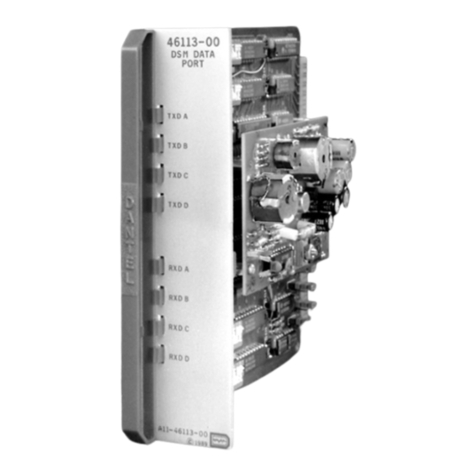
Dantel A18-05721 Series User manual

CAUTION
Install or remove modules from the shelf only when the power is off.
If you install a module in the shelf with the power on, the internal
circuitry may suffer damage and the product warranty will be void.
Remove and install circuit boards only in a static-safe environment
(use antistatic wrist straps, smocks, footwear, etc.).
Keep circuit boards in their antistatic bags when they are not in use.
Do not ship or store circuit boards near strong electrostatic, electromag-
netic, magnetic, or radioactive fields.
For more complete information on electrostatic discharge safety
precautions, refer to BellcoreTM Technical Reference #TR-NWT-000870.
Copyright 1998 by Dantel, Inc. • Dantel is a registered trademark of Dantel, Inc. • ISO 9001 Registered
Printed in the U.S.A.
INSTALLATION&OPERATION MANUAL
05721-1098<90-00050>
DIGITAL SERVICE MULTIPLEXOR
SHELF SERVICE NODE LOCATION
A18-05721-XX
About this Practice:
This practice has been reissued to:
• Update Service Node Description
in
General Description
section.
• Update the table in Step 4A, in
Installation
section.
• Update margin note in step 5A.
issue date: October 1998
Reissued Practices: Updated and
new content can be identified by a
banner in the right margin.
UPDATED
Table of Contents
Ordering Information ........................................................................... 2
General Description.............................................................................. 2
Installation............................................................................................ 9
Support Documentation ..................................................................... 25
Warranty ............................................................................................. 26

PAGE 2 05721-1098<90-00050>
NOTE: This section lists the different options available for this product. To order any of the avail-
able options, contact Dantel Inside Sales through our toll-free number, 1-800-432-6835.
OPTION NUMBER FEATURES
A18-05721-00 Service Node Assembly; Wired; Not equipped
A18-05721-01 Service Node Assembly; Wired; Equipped for up to 2 LSO Locations
A18-05721-02 Service Node Assembly; Wired; Equipped for up to 4 LSO Locations
A18-05721-03 Service Node Assembly; Wired; Equipped for up to 6 LSO Locations
A18-05721-04 Service Node Assembly; Wired; Equipped for up to 8 LSO Locations
A18-05721-05 Service Node Assembly; Wired; Equipped for up to 10 LSO Locations
A18-05721-06 Service Node Assembly; Wired; Equipped for up to 12 LSO Locations
A18-05721-07 Service Node Assembly; Wired; Equipped for up to 15 LSO Locations
ORDERING INFORMATION
GENERAL DESCRIPTION
T
he Service Node Digital Service Multiplexor (DSM) Shelf
described in this manual is offered in a number of different
configurations. Refer to Ordering Information above.
The DSM is composed of two basic modules. Refer to Figs. 1, 2,
and 3 for front, rear, and side views of the 05721 system. The B11-
46112-00 Controller Module and the B11-46113-00 Data Port
Module. The Controller Module is used to interface the 64Kb
channel using a RS-422 interface and to interface the Data Port
Modules. Each Controller can accommodate up to 8 Data Port
Modules. Each Multi Port Module can provide for up to four
RS-232 or RS-422 ports. In this application only the RS-232 ports
will be wired to DB-25 connectors. The total number of ports that
can be provided from a Controller and Port Modules is 32. The
DSM can be optioned so that the channels can terminate at a
location or they can be repeated to the next locations. At the
Service Node, all channels are set for terminal application.
The purpose of this system is to provide RS-232 ports from the
Service Node to every Local Serving Office (LSO) site. This will
allow for transmission of ASCII information on the 64Kb OW
channel of fiber systems such as FT 2000 terminals. This could be
ASCII data such as TL1 messages from Telecom Solutions DCD-23
BITS clock or TL1 messages from other Network Elements (NEs).
This application will also provide for an additional RS-232, 1200
baud port at every LSO. This system will provide for a self healing
ring on the 64 kb channel and it will provide for alarm information
for maintenance and fault location of the ring.
NOTE:
Practices for the various modules
are located in the Appendix of
this manual. Block and level
drawings for this assembly are
located in the back of this manu-
al.

05721-1098<90-00050> PAGE 3
Specific Application
This application consists of two basic assemblies. A18-05720-XX for
the Local Serving Office (LSO) and the A18-05721-XX Service Node
assemblies. These assemblies will work together to make a self
healing system with two RS-232 ASCII ports at every LSO and one
Alarm channel that is common to all LSO locations. Each Channel
will terminate at the Service Node on DB25 connectors configured
as DTE, RS-232 interfaces.
FIG. 1 - FRONT VIEW, 05721 SYSTEM
NOTE: For a larger, more detailed drawing of the above, please refer to
Sheet # 8 of the A18-05721-XX Block Diagram.
GENERAL DESCRIPTION
SHELF 'A'
SHELF 'B'
SHELF 'C'
SHELF 'D'

PAGE 4 05721-1098<90-00050>
FIG. 2 - REAR VIEW, 05721 SYSTEM
NOTE: For a larger, more detailed drawing of the above, please refer to
Sheet # 9 of the A18-05721-XX Block Diagram.
GENERAL DESCRIPTION
SHELF 'A'SHELF 'A'SHELF 'B'
SHELF 'C'
SHELF 'D'

05721-1098<90-00050> PAGE 5
FIG. 3 - SIDE VIEW, 05721 SYSTEM
NOTE: For a larger, more detailed drawing of the above, please refer to
Sheet # 9 of the A18-05721-XX Block Diagram.
GENERAL DESCRIPTION
SYSTEM SIDE VIEW
REAR PANEL ASSEMBLY REAR PANEL ASSEMBLY REAR PANEL ASSEMBLY
SHELF 'D'
SHELF 'A'
SHELF ''C'
SHELF ''B'

PAGE 6 05721-1098<90-00050>
SERVICE NODE ASSEMBLY
The Service Node provides for 30 self-healing channels on a fiber
ring application, one self-healing alarm channel, and one pilot
channel. The assembly will consist of two Controllers, 16 Data
Port Modules, and Hubbing Modules to allow for the transmission
and reception of data from the East and West directions of the
ring. A Multi-Alarm Transmitter (MAT) is used to monitor the
synch on the local terminals, to monitor the ring continuity of the
system, and to monitor the local power supplies for the Controller
cards. A Multi-Alarm Processor (MAP) is used to interrogate all of
the MATs at the LSOs for faults. A General Purpose Processor
(GPP) then polls the MAP and converts the detected faults to TL1
alarm messages that are sent to the OS over a Datakit channel.
In this application, the DSMs are set up to act as a self-healing
ring. At the Service Node, data will normally be transmitted in a
West to East direction (clockwise). Data is received in an East to
West direction (counter-clockwise). When the system is intact, the
East DSM is opened and no data is transmitted or received by it.
When the MAT at the Service Node detects a fault on the ring in
either direction, the system will self-heal by transmitting or
receiving in the opposite direction in order to avoid the fault.
SERVICE NODE DESCRIPTION
The Service Node location can send or receive data from either
direction. Refer to Fig. 4. The data to and from the East Port
modules is opened if there is no faults on the system. An RS-232
signal is sent around the ring in both directions, East to West and
West to East. The opposite ends of the ring have detectors on them
so that there is continuous monitoring of the continuity of the
system in both directions.
If there is no fault on the system, data is transmitted from the
West to the East, and data is received from the East to West
direction. An RS-232 signal, used for continuity checking, is sent
out on channel 31 with a known pattern and in a known time slot
on the data string. This data string will also contain framing
information. This will assure that noise cannot cause a false
indication. There is a 300 millisecond delay upon the loss of signal
before the detect takes place.
The detected RS-232 signals are sent to the MAT at the Service
Node. If there is a failure on the ring, the MAT will energize one of
two relays, depending on the failure direction, and this relay will
trigger additional relays that will cause the data path to reverse
direction. (This can be either the transmission path or the receive
path, depending on the failure direction.)
If there is a failure from the West to East direction, the MAT
alarm point associated with the continuity check for the West to
East loop cannot detect the RS-232 signal at the Service Node, and
the logic will energize relays 12A and 13A. All transmit and
GENERAL DESCRIPTION
05721-1098<90-00050> PAGE 7
FIG.4- TERMINAL LOCATION SERVICE NODE
GENERAL DESCRIPTION
FT 2000
OW INTERFACE
311 412 19614
FT 2000
OW INTERFACE
311 412 19614
WEST EAST
A11-46112-00
DATA CONTROLLER
910 3 4 5 6 1 2
A11-46112-00
DATA CONTROLLER
9103 4 5 6 1 2
A11-46113-00
DATA PORT
MODULE #1
PORT
MODULES
2-8
PORT
MODULES
2-8
A B C D
An RS-232 signal is sent around the ring in both
directions and it is used to detect ring continuity by the
MAT module.
If there is a failure in the East to West direction relays
10A & 11A operate and receive path reverses.
If there is a failure in the West to East direction relays
12A & 13A operate and transmission path reverses.
If there is a failure in both directions all relays operate.
Transmission and reception will go both directions.
If the system is back to normal all relays will be as
shown.
BYPASS
1/3 OF
HUB 11
A11-46113-00
DATA PORT
MODULE #1
A B C D
RELAY MODULES 10A & 11A
RELAY MODULES 10B TO 13B
RELAY MODULES 12A & 13A
RELAY MODULES 10B TO 13B
RELAY MODULES 10A & 11A
RELAY MODULES 10B TO 13B
RELAY MODULES 12A & 13A
RELAY MODULES 10B TO 13B
C11-46020-40
MAP
A12-49029-00 BYPASS
A11-46010-13
MAT
A11-46062-22
GPP
TL1
MAINTENANCE
PORTS
CONTROL E-W & W-E
RELAYS MODULES
1 TO 8
RS-232 TL1
TO OS
HUBS
2-10
2/3 OF
HUB 1
CHANNEL 1 CHANNEL 2 CHANNEL 3-30 CHANNEL 31
TL1 TL1 A11-44930-00
RELAY MODULE
#1
A11-44930-00
RELAY MODULE
#8
RELAY MODULES 2-7
EAST
WEST
+5V
TERMINAL LOCATION
SERVICE NODE

PAGE 8 05721-1098<90-00050>
receive data is shifted to the East to West direction. The transmis-
sion is now around the ring in the East to West, counter-clockwise
direction, while the receive is still in the same direction. The East
to West pair is intact with no fault detected on it.
If there was a failure on the system from the East to the West,
Relays 10A and 11A would energize. The transmit path would
remain West to East, but the receive path direction reverses so
that it, too, is West to East.
If there is a cut causing failures in both directions, this will cause
ring fault detect alarms in both directions and all of the transfer
relays 10A to 13B would operate. Data transmission and reception
would then go both directions from the Service Node. Data would
be transmitted from the West to the East up to the break location
and data would be received from the break in the East to West
direction. Every LSO on the West side of the break would report in
this manner. Every LSO to the East of the break would now
transmit data from the West to the East direction and the LSOs
would receive from the East to West direction. There would be no
conflict of data because of the complete opening of the system at
the break location.
ALARM CONDITION ASSIGNMENTS
The MAT at the Service node will monitor the alarm conditions,
assigned as follows:
♦Point 1 = East Sync alarm
♦Point 2 = East DSM Power Supply alarm
♦Point 3 = Continuity East Loss of Signal alarm
♦Point 4 = West Sync alarm
♦Point 5 = West DSM Power Supply alarm
♦Point 6, 9 = Continuity West Loss of Signal alarm
♦Point 7 = Blown fuse alarm
♦Point 8 = Customer use (logic for points 1 to 8 reversed)
♦Points 10 to 16 for customer use
The MAP, being polled by the GPP, will pass the detected alarms
to the GPP. The GPP will then create TL1 messages based on the
alarm inputs from the MAP. The database created for the GPP
can be generic in nature so that all systems could be databased the
same with only the SIDs being different. The user would only have
to change one entry in the data base for each MAP database
entered into the GPP. The GPP can support up to 50,000 TL1
messages.
GENERAL DESCRIPTION
UPDATED

05721-1098<90-00050> PAGE 9
The database can be created so that the AID for each point could
be descriptive of the location and the type of alarm. The GPP can
support up to 4,096 different AIDs. If the GPP is centrally located,
one GPP can be used to poll a number of different Service Nodes. It
would only require that there be a data link between the sites to
allow the different MAPs from the Service Nodes to communicate
with the GPP at the central location. A Hubbing Module has been
provided to accommodate additional remote MAP ports. It can also
be used for other purposes.
The GPP will create autonomous TL1 alarm messages and it will
accept TL1 commands from the operations center such as RTRV-
HDR, INH-MSG, date/time setting routines, etc.
GENERAL DESCRIPTION
INSTALLATION
TURN-UP PROCEDURE
The following is a step-by-step procedure for turning-up the
shelf after it has been mounted in an equipment rack and all
wiring has been completed.
STEP 1 - MODULE INFORMATION
If the modules are installed in the shelf, remove the Fuse
Module first, then remove all the other modules.
CAUTION: Modules should only be installed or removed from the shelf
after power has been shut off (by removing the Fuse Module).
Installing modules in the shelf with power applied may
damage internal circuitry and void the product warranty.
Observe electrostatic precautions when handling modules.
Refer to Bellcore Technical Advisory #TA-TSY-00878, Section
7, for electrostatic discharge information.
STEP 2 - 46112 STRAPPING INFORMATION
Refer to Figure 5 for strap locations. Set 46112 switches and
straps per following table:
B11-46112 STRAPPING INFORMATION FOR
ALL CONTROLLERS
SHELF A & B, SLOT 1
X1
1 to 2
X2
2 to 3
SUBASSEMBLY
X1
2 to 3
X2
2 to 3
X3
2 to 3

PAGE 10 05721-1098<90-00050>
FIG. 5 - 46112 DSM DATA CONTROLLER MODULE STRAP LOCATION
INSTALLATION
Terminated
Open
3
2
1
3
2
1
3
2
1
3
2
1
3
2
1
1 2 3 1 2 3
RS422
INTERFACE
SUBASS'Y
X1 X2 SUBASSEMBLY
STRAPPING OPTIONS
POSITION
STRAPS
X1, X2 and X3
T
O
X1
X2
X3

05721-1098<90-00050> PAGE 11
STEP 3 - 46113-00 SWITCH SETTINGS
Refer to Figure 6 for switch and strap locations. Set the 46113
switches and straps per following table:
INSTALLATION
B11-46113-00 SWITCH SETTINGS FOR SERVICE NODE (SWITCHES SHOWN ARE ON; ALL OTHERS OFF)
Port A
S1 S5
Port B
S2 S6
Port D
S4 S8
Port C
S3 S7
SHELF A
Slot 2
Slot 3
Slot 4
Slot 5
Slot 6
Slot 7
Slot 8
Slot 9
SHELF B
Slot 2
Slot 3
Slot 4
Slot 5
Slot 6
Slot 7
Slot 8
Slot 9
All OFF
3
2
2,3
1
1,3
1,2
1,2,3
All OFF
3
2
2,3
1
1,3
1,2
1,2,3
1,2,5,8
1,2,5,8
1,2,5,8
1,2,5,8
1,2,5,8
1,2,5,8
1,2,5,8
1,2,5,8
1,2,5,8
1,2,5,8
1,2,5,8
1,2,5,8
1,2,5,8
1,2,5,8
1,2,5,8
1,2,5,8
5
3,5
2,5
2,3,5
1,5
1,3,5
1,2,5
1,2,4,5
5
3,5
2,5
2,3,5
1,5
1,3,5
1,2,5
1,2,4,5
1,2,5,8
1,2,5,8
1,2,5,8
1,2,5,8
1,2,5,8
1,2,5,8
1,2,5,8
1,2,5,8
1,2,5,8
1,2,5,8
1,2,5,8
1,2,5,8
1,2,5,8
1,2,5,8
1,2,5,8
1,2,5,8
4
3,4
2,4
2,3,4
1,4
1,3,4
1,2,4
1,2,3,4
4
3,4
2,4
2,3,4
1,4
1,3,4
1,2,4
1,2,3,4
1,2,5,8
1,2,5,8
1,2,5,8
1,2,5,8
1,2,5,8
1,2,5,8
1,2,5,8
1,2,4,8
1,2,5,8
1,2,5,8
1,2,5,8
1,2,5,8
1,2,5,8
1,2,5,8
1,2,5,8
1,2,4,8
4,5
3,4,5
2,4,5
2,3,4,5
1,4,5
1,3,4,5
1,2,4,5
1,2,3,4,5
4,5
3,4,5
2,4,5
2,3,4,5
1,4,5
1,3,4,5
1,2,4,5
1,2,3,4,5
1,2,5,8
1,2,5,8
1,2,5,8
1,2,5,8
1,2,5,8
1,2,5,8
1,2,5,8
1,2,5,8
1,2,5,8
1,2,5,8
1,2,5,8
1,2,5,8
1,2,5,8
1,2,5,8
1,2,5,8
1,2,5,8
NOTE: AT SERVICE NODE, SET STRAPS X1, X2, X3, AND X4 ON ALL 46113 CARDS TO “G” (1 TO 2)

PAGE 12 05721-1098<90-00050>
FIG. 6 - 46113 DSM DATA PORT MODULE STRAP AND SWITCH LOCATIONS
INSTALLATION
NOTE:
SUBASSEMBLY
STRAPPING
OPTIONS
POSITION STRAPS
X1, X2, X3 and X4
"G" RS232
"T" RS422
"O" RS422
= RS-232 (default)
= RS-422
TERMINATED
= RS-422
NON-TERMINATED
X1
X2
X3
X4
123123
4
123
123
4
123
4
123
4
ON
OFF
POWER
SUPPLY
S5
1234567812345
S1
S6
1234567812345
S2
S7
1234567812345
S3
S8
1234567812345
S4
1 - 2 = RS- 232
2 - 3 = TERMINATED
2 - 4 = RS-422 UNTERMINATED
X1 = Port A
X2 = Port B
X3 = Port C
X4 = Port D

05721-1098<90-00050> PAGE 13
STEP 4A - 46034 HUBBING MODULES
Refer to Figure 7 for switch and strap locations. Set the 46034
switches and straps per following table:
INSTALLATION
SWITCH
1
2
3
4
5
6
7
8
9
10
11
12
13
14
15
16
17
18
19
20
21
22
STRAPS
1A to 8A
1B to 8B
C
D
POSITION
1 ON
1 ON
2 ON
3 ON
3 ON
4 ON
5 ON
5 ON
2 ON
2 ON
1 ON
4 ON
4 ON
3 ON
6 ON
6 ON
6 ON
All OFF
5 ON
All OFF
All OFF
All OFF
3
1
2
1
SLOTS 1 - 10 SLOT 11
POSITION
5 ON
5 ON
As needed
As needed
As needed
As needed
As needed
As needed
6 ON
6 ON
As needed
As needed
As needed
As needed
As needed
As needed
6 ON
All OFF
5 ON
All OFF
All OFF
All OFF
3
1
2
1
STEP 4B - 46034 HUBBING MODULES
Refer to Step 9 and strap the 49029 communication subassem-
blies in slots 1 through 10.
UPDATED

PAGE 14 05721-1098<90-00050>
FIG. 7 - SWITCH AND STRAP LOCATIONS, 46034 HUBBING MODULE
NOTE: Refer to step 9 for strap and switch information on the 49029
subassembly mounted on the Hubbing Modules
INSTALLATION
123456
O
123456
ON
123456
ON
123456
ON
123456
ON
123456
ON
123456
ON
123456
ON
123456
ON
123456
ON
123456
ON
123456
ON
123456
O
123456
ON
123456
ON
123456
ON
123456
ON
123456
ON
123456
ON
123456
ON
123456
O
S17 S18 S1
XX XX
S4 S5 S6 S7 S8
S19 S20 S9 S10 S11 S12 S13 S14 S15 S16
S21
3A 2A
2 1 3
2 1 3
2 1 3
6A
2 1 3
1A
2 1 3
2B
1 2
4B
1 2
6B
1 2
8B
1 2
1B
1 2
3B
1 2
5B
1 2
7B
1 2
3
1
2
S22
1 8
8A
7A
D
1 2
C
1 2
2 1 3
2 1 3
5A
4A

05721-1098<90-00050> PAGE 15
STEP 5A - B11-46020-00 MAP
Refer to Figures 8 and 9 for MAP switch locations. Set switch
settings of 46020-40 per following table:
After switches are set, the MAP will require configuration.
Connect a computer to C1 of the 46090 in slot 2 of shelf D, or to
C7 of shelf C. Use the A22-46508 T/Shell practice for instruc-
tions. Master port is set for 1200 baud. Printer port is set for
1200 baud.
STEP 5B - B11-46020-00 MAP
Interpoll Delay is a feature of the 46020-40 Multiple Alarm
Processor (MAP). Refer to the 46020-40 Installation and Opera-
tion Manual, Printer Syntax section. This command is used to
configure the MAP to interrogate the Multi- Alarm Transmitters
(MATs) through a large number of LSOs.
Using the MAP's printer port, set the IPD value to 128 (500ms).
The command is IPD 128. This allows enough time for the MAP
to poll a MAT and to receive that MATs response before polling
the next MAT. Refer to the 46020-40 Manual, Printer Syntax
section for more details on the use of this command.
INSTALLATION
Shelf C
Slot 12
B11-46020-40 MAP SWITCH SETTINGS AT SERVICE NODE
SWITCHES SHOWN ARE ON (DOWN)
S1
All ON
S2
All ON
S3
1,2,3,5,6,7
S7
All OFF
S6
3,4,5,7,8
S5
All OFF
S4
1,2,3,5,6,7
Master Port = 1200 baud, DCP/F protocol. Printer Port = 1200 baud, Printer
protocol. Both ports = 1 stop bit, 8 word length, no parity.
NOTE:
Level of alarms for MAT 16,
point 3 must be A, point 6 must
be B, and point 9 must be C.
All other points must be D.
NOTE UPDATED

PAGE 16 05721-1098<90-00050>
FIG. 8 - MAP SUBASSEMBLY LOCATIONS
INSTALLATION
STEP 5C - B11-46020-00 MAP
Refer to Step 9 and set the straps on the 49029 communication
subassembly.
DATA
XMT
LED
RESET SWITCH
8 7 6 5 4 3 2 18 7 6 5 4 3 2 1
S4 S3 S2
8 7 6 5 4 3 2 1
87654321
S7
87654321
S5
87654321
S6
FIRMWARE
SUBASSEMBLY
113
1
4
J5
J4
8 7 6 5 4 3 2 1
S1

05721-1098<90-00050> PAGE 17
INSTALLATION
Shelf 3
Slot 13
A11-46010-13 MAT SWITCH SETTGINS AT SERVICE NODE
(LISTED SWITCHES ARE IN THE ON (DOWN) POSITION)
S3
1,3
S104
1
S103
3
S4
1,3,5
S102
All OFF
S101
3,6
S5
1,5,6,7,8
FIG. 9 - 46020 MAP VIEWED FROM THE TOP
STEP 6 - 46010-13 MAT SWITCH SETTING
Refer to Figure 10 for switch locations. Set 46010 switches per
the following table:
MAT will be set for address 16, 1200 baud, normal mode, input
reversal for points 1-8. Alarm point 3 to operate A level relay,
alarm point 6 to operate B level relay, and alarm point 9 to
operate C level relay. All other alarms to operate level D relay.
VIEW
ROTATED
90 DEGREES
1 2 3 4 5 6 7 8 1 2 3 4 5 6 7 8 1 2 3 4 5 6 7 8 1 2 3 4 5 6 7 8
SWITCH 1 SWITCH 2 SWITCH 3 SWITCH 4
UP = OFF
DOWN = ON
1 2 3 4 5 6 7 8
1 2 3 4 5 6 7 8
1 2 3 4 5 6 7 8
S5
S6
S7
1 2 3 4 5 6 7 8
SWITCH 5

PAGE 18 05721-1098<90-00050>
FIG. 10 - MAT SWITCH LOCATIONS
INSTALLATION
STEP 7 - 46062 GPP SETTINGS
Master Port: RS-232, 1200 baud, TL1, TL1 mode by computer,
memory hold on power-up or reset, no parity
Data Port: DCPF, 1200 baud, no parity, 1 stop bit,
Printer Port: Printer syntax, 1200 baud, 1 stop bit, no parity
The GPP will require a download of the Operating software and
the Database for the GPP. See 46504 T/Shell editor practice for
instructions. Connect a computer that contains the T/Shell
editor to C2 of the 46090 in slot 2, shelf D, or to C2D of the D
shelf.
Refer to Fig. 11 for switch and strap locations. Set 46062 strap
settings per following table:
Shelf D
Slot 1
A11-46062-22 GPP SETTINGS AT SERVICE NODE
SWITCHES LISTED ARE IN THE ON (DOWN) POSITION
S1
all on
S2
all on
S3
1,2,3,4,5,6,7
Master Port jumpers = K3, CC2, DD1, L2, EE1, N1, M2
Data Port jumpers = C1, A1
GPP will be factory-set for RS-232 on all ports. Operating
software and database is required to operate GPP.
S101
S102
S103
S104
113
1
4
J5
J4
SUBASSEMBLY
MOUNTING
AREA
S5 S4 S3
12345678 12345678
87654321
87654321
87654321
87654321
(-13 OPTION ONLY)
UP = OFF
DOWN = ON
12345678

05721-1098<90-00050> PAGE 19
FIG. 11 - GPP SWITCH AND STRAP LOCATIONS
GREEN LEDS
MASTER
PRINTER
DATA
S3S2S1
DOWN = ON
GPP CARD
POWER
SUPPLY
SUBASSEMBLY
BOARD-TO-BOARD CONNECTOR PINS
123456781234567812345678
818181
INSTALLATION

PAGE 20 05721-1098<90-00050>
STEP 8 - 46017 SWITCH INFORMATION
Refer to Figure 12 for switch locations. Set the 46017 switches
per requirements. Times are not additive. Only one switch may
be on at a time. Refer to the following table:
A11-46017-01 SWITCH OPTIONS
SHELF D, SLOT 3
TIME-OUT IN...
1 minute *
4 minutes
8 minutes
16 minutes
No time-out
S1-1
ON
OFF
OFF
OFF
OFF
S1-2
OFF
ON
OFF
OFF
OFF
S1-3
OFF
OFF
ON
OFF
OFF
S1-4
OFF
OFF
OFF
ON
OFF
FIG. 12 - 46017 SUMMARY ALARM MODULE SWITCH LOCATION
INSTALLATION
* Default setting
1234
OFF
ON
This manual suits for next models
8
Table of contents
Other Dantel Controllers manuals

Dantel
Dantel SynchMaster 46112 User manual

Dantel
Dantel A18-05775 Series User manual

Dantel
Dantel B18-05776 Series User manual

Dantel
Dantel 41096 User manual

Dantel
Dantel PointMaster TL1 User manual

Dantel
Dantel 41095 User manual

Dantel
Dantel 46210 User manual

Dantel
Dantel 46023-12 User manual

Dantel
Dantel 44443 User manual