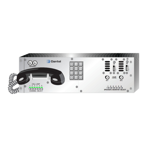
Dantel B18-05776 Series User manual

CAUTION
•Install or remove modules from the shelf only when the power is off.
If you install a module in the shelf with the power on, the internal
circuitry may suffer damage and the product warranty will be void.
•Remove and install circuit boards only in a static-safe environment
(use antistatic wrist straps, smocks, footwear, etc.).
•Keep circuit boards in their antistatic bags when they are not in use.
•Do not ship or store circuit boards near strong electrostatic, electromag-
netic, magnetic, or radioactive fields.
•For more complete information on electrostatic discharge safety
precautions, refer to BellcoreTM Technical Reference # TR-NWT-000870.
Copyright 1998 by Dantel, Inc. • Dantel is a registered trademark of Dantel, Inc. • ISO 9001 Registered
Printed in the U.S.A.
INSTALLATION & OPERATION MANUAL
05776-1198 <90-00124>
B18-05776-XX
UNIVERSAL
ORDER WIRE
ASSEMBLY
About this Practice:
This practice has been reissued to:
• Document B18 release with new
M Lead Interface Module.
• Update Figs. 2, 3, and 6.
Issue date: November 1998
Reissued Practices: Updated and
new content can be identified by a
banner in the right margin.
UPDATED
Table of Contents
Ordering Information ........................................................................... 2
General Description.............................................................................. 2
Installation............................................................................................ 3
Alignment Procedures .......................................................................... 9
Operation ............................................................................................ 15
Technical Specifications ..................................................................... 16
Warranty ............................................................................................. 18
A11-44118-00
44118-00
DISTRIBUTION
BRIDGE
LINE RCV
PORT 1
PORT 2
PORT 3
PORT 4
COMBINED
DIST
OUTPUT
PORT 1
PORT 2
PORT 3
PORT 4
LINE XMT
44118-00 REV__
A11-44020-00 REV__
STROBE
CKT 2
O/1
GND
LEVEL
46105-00REV__
CH 1
XMT
RCV
SYNC
RCV
RCV
SYNC
GND
LEVEL
XMT
RCV
RCV
MON DROP
XMT
CH 2
MON DROP
XMT
RCV
46105-XX
DUAL VF
64B CHAN
44022-00
STATION
INTERFACE
GND
LINE
DROP MON
TRANSMIT
DIST
GND
LINE
DROP MON
RECEIVE
DIST
Busy
Inc. Call
Off Hook
B11-44022-00 REV__
TEST RST

PAGE 2 05776-1198 <90-00124>
NOTE: This section lists the different options available for this product. To order any of the avail-
able options, contact Dantel Inside Sales through our toll-free number, 1-800-432-6835.
OPTION NUMBER FEATURES
B18-05776-00 Wired only. No modules
B18-05776-01 Wired shelf equipped with one 46105 Dual VF 64Kb Channel module; one 44022 Subscriber
Line Interface module; and one 44118 4W/4W VF Bridge.
B18-05776-02 Equipped the same as the -01 option above; less the 46105.
ORDERING INFORMATION
GENERAL DESCRIPTION
This shelf is designed to be a 4-wire analog or digital order
wire assembly (OW). It is wired for:
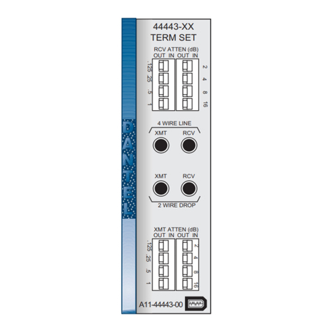
♦44022-00 (A17-44022-00) Subscriber Line Interface module
♦44118-00 (A17-44118-00) 4W/4W VF Bridge
♦46105-00 (A17-46105-00) Dual VF 64 Kb Channel module.
The 05776 is equipped to use a 4-wire telephone such as the
A23-00010-20 or an A18-05775-00 3 channel OW speaker moni-
tor panel. No DTMF decoding is provided for this unit. DTMF
signaling is only used to get access to the VNET interface to the
PBX.
The unit is designed as a party-line system so that a caller, on
the OW channel, will simply speak into the handset and call who
he wants to talk to. The same is true from a call coming in from
the Off-Net package. The Off-Net unit associated with this
system will be the VNET PBX assembly A18-05774.
The 05776 operates from -21 to -56 volts with levels of +7 to
-16 dBm on any port of the 44118 VF bridge. In this application
all ports of the bridge will be set for -16 dBm on the transmit
ports and +7 dBm on the receive ports. The OW interface will be
made up of:
♦A 46105-00 Dual VF card in slot 1 (J1)
♦A 4118-00 4w/4w bridge in slot 2 (J2)
♦A 44022-00 subscriber line interface in slot 3 (J3).
NOTE:
With the release of the
B18-05776-XX Universal Order-
wire assembly, the A80-00630-00
M lead interface module has
been added.
This assembly will allow for con-
trol of M lead devices that re-
quire RS-232 or RS-449 RTS
leads to enable the 64 kb chan-
nels. The interface module can be
provisioned so that the on-hook
idle condition is normal low or
normal high.
UPDATED
NEW NOTE
05776-1198 <90-00124> PAGE 3
INSTALLATION
This section consists of:
♦Equipment mounting
♦Wiring
♦Switch and strap settings
44118 Bridge
44022 Subscriber Line Interface
46105 Dual VF 64Kb Channel
EQUIPMENT MOUNTING
Install the shelf in an equipment rack using the hardware
provided. Refer to Fig. 1.
FIG. 1 - MOUNTING DIMENSIONS
WIRING
Wire the shelf as required. Refer to Fig. 2 for a functional
schematic of the unit. Fig. 3 shows the connector locations on
the rear of the unit.
8.5
4.75
1.72
17.35
19.00 or 23.00

PAGE 4 05776-1198 <90-00124>
FIG. 2 - FUNCTIONAL SCHEMATIC, 05776 SHELF
INSTALLATION
UPDATED

05776-1198 <90-00124> PAGE 5
FIG. 3 - REAR VIEW, 05776 SHELF
OPTION
GAIN STRAPS
Receive Port 1
0 to +7 dB
Receive Port 2
0 to +7 dB
Receive Port 3
0 to +7 dB
Receive Port 4
0 to -16 dB
Transmit Port 1
0 to -16 dB
Transmit Port 2
0 to -16 dB
Transmit Port 3
0 to -16 dB
Transmit Port 4
0 to +7 dB
FOUR-WAY BRIDGE
Summing Bus IN
Transmit Distribution Networks OUT
Receive Distribution Networks OUT
STRAP IN
1R LO
2R LO
3R LO
4R LO
1X LO
2X LO
3X LO
4X LO
B1X, B2X, B3X, B4X
D1H, D2H, D3H, D4H
H1R, H2R, H3R, H4R
INSTALLATION
SWITCH AND STRAP SETTINGS
Refer to Tables A through C and Fig. 4 through 6 to set the
straps and switches on the modules.
TABLE A - SWITCH AND STRAP SETTINGS, 44118 BRIDGE
NOTE:
All switches, straps, and levels
are factory-set.
UPDATED
1 2 3 4 5 6 7 8 9 10
BC1
J1
J2
J3
C2
RJ 2 RJ 1
1
2
56
55
REV NORM
S1 S2
REV NORM
P1
2
15 17 41
C.O. Matching Adapt. Sub-Assembly
Installation Detail
REVERSED SWITCHES
CHANNEL 1
EAST
CHANNEL 2
WEST
CHANNEL 2
OUTPUT-WEST
CHANNEL 1
OUTPUT-EAST
With the reversing switches in the
right, or NORM position (viewed from
the back), the associated idle output
(on hook) is low and high when the de-
vice is off hook. With the switch in the
REV position, the idle output is high
and low with an off hook.
S1 and S2 are shipped from the factory
in the REV position.

PAGE 6 05776-1198 <90-00124>
FIG. 4 - SWITCH AND STRAP LOCATIONS, 44118 BRIDGE
STRAP
ALL CALL AND GROUP CALL RINGBACK TONE
Group Call
All Call LINE RECEIVE; 4-WIRE RCV LEVEL
-16 dBm to -3 dBm
LINE TRANSMIT; 4-WIRE XMT LEVEL
-3 dBm to +7 dBm
REMOTE M LEAD CONTROL
By incoming call (with radios)
PRIVACY
No Privacy (normal for order wire applications)
2-WIRE/4-WIRE (DROP)
4-Wire SIDETONE
4-Wire; with sidetone
4-WIRE DROP RCV IMPEDANCE
600 ohms
Ring Generator
OPTION
GP
ALL
RCV PAD OUT
XMT PAD OUT
IN
PRIVACY OUT
4W (Straps horizontal)
SIDETONE IN
600 OHMS (Straps horizontal)
OUT (always)
INSTALLATION
TABLE B - SWITCH AND STRAP SETTINGS, 44022 SUBSCRIBER LINE INTERFACE
HI LO
1R
HI LO
3R
HI LO
2X
+ +
+
+
+
+
HI LO
2R
LO HI
HI LO
4X
+
+
+
+
+
+
H1R
D1R
D3X
H3R D3R
H2R
D2R
H4R D4R
G3X B3X
D3H
HI
LO
1X
+
++
+
+
+
+
B2X D2H
D2X
G2X
G1X
B1X D1H
D1X
D4X
D4H
B4X
G4X
HI LO
4R
3X

05776-1198 <90-00124> PAGE 7
INSTALLATION
FIG. 5• - STRAP LOCATIONS, 44022 SUBSCRIBER LINE INTERFACE
TABLE C - STRAP AND SWITCH SETTINGS, 46105 DUAL VF 64KBCHANNEL
DESCRIPTION
180-ohm termination across RS-422 inputs at pins 51 and 52
180-ohm termination across RS-422 inputs at pins 45 and 46
180-ohm termination across RS-422 inputs at pins 43 and 44
180-ohm termination across RS-422 inputs at pins 5 and 6
180-ohm termination across RS-422 inputs at pins 11 and 12
180-ohm termination across RS-422 inputs at pins 13 and 14
Relay at pins 39 and 40 is normally open when E Lead 1 is active
Relay at pins 19 and 20 is normally open when E Lead 2 is active
M Lead 1 input at pins 41 and 42 is used
M Lead 2 input at pins 15 and 16 is used
Digital sections of channel 1 and 2 are interconnected, bypassing the
analog sections when they are not in use. Select this position when the
channels are bridged together in the repeater mode.
BRDG switch also must be in the RPTR position.
STRAP
XMT CLK
RCV CLK 1
RCV DATA 1
XMT CLK 2
RCV CLK 2
RCV DATA 2
E LEAD 1
E LEAD 2
M LEAD 1
M LEAD 2
MODE
POSITION
TERM
TERM
TERM
TERM
TERM
TERM
NO
NO
YES
YES
RPTR
SWITCH
BRDG (S1)
LPBK 1
LPBK 2
POSITION
RPTR
OFF
OFF
DESCRIPTION
Channels 1 and 2 are bridged together.
Analog signals for Channel 1 are not looped back.
Analog signals for Channel 2 are not looped back.
XMT
DISTRIBUTION
OUTPUT TP
XMT DROP
2W/4W
TEST JACKS
RCV
DISTRIBUTION
OUTPUT TP
RCV LEVEL
ADJUST
SIDE TONE
IN OUT
IN OUT
10dB XMT
PRIVACY
REMOTE
M LEAD
OUT
IN
OUT
IN
OUT
IN
ALL
GRP
RCV PAD
OUT
IN
RG
600 OHM
600 OHM
0 OHM
0 OHM
4W
4W
2W2W
R51
R4
RING TRIP
SENSE ADJUST
R38
44022-00
STATION
INTERFACE
XMT
LINE TP
GND
LINE
DROP MON
TRANSMIT
DIST
GND
LINE
DROP MON
RECEIVE
DIST
RCV
LINE TP
RCV DROP
4W
TEST JACKS
STATUS LED
INDICATORS
XMT LEVEL
ADJUST
TEST/RESET
SWITCH
Busy
Inc. Call
Off Hook
B11-44022-00 REV__
TEST RST

PAGE 8 05776-1198 <90-00124>
FIG. 6 - SWITCH AND STRAP LOCATIONS, 46105 DUAL VF 64KBCHANNEL
INSTALLATION
MODE
E LEAD
TERM RPTR
NO YES
LPBK 1
OFF ON
LPBK 2
BRDG
CHANNEL
2
CHANNEL 1
M LEAD 2
OFF ON
DATA
CLK
CLK
RCV
RCV
XMT
NO
NC
TERM
TTL
TM
T-
T+
TM
T-
T+
TERM
RPTR
S101
S2
S1
T
T
L
T
E
R
M
RCV
DATA
T
T
L
-
T
T
L
+
T
E
R
M
RCV CLK
T
T
L
-
T
T
L
+
T
E
R
M
XMT CLK
Y
E
S
N
O
M LEAD
N
C
N
D
E LEAD
UPDATED

05776-1198 <90-00124> PAGE 9
ALIGNMENT PROCEDURES
All straps and levels are factory-set. If necessary, refer to the
steps below to align the 44022, 44118, and 46105 modules.
Equipment Required
♦Signal Generator sending a 1kHz, 600 ohm signal at various
levels.
♦600-ohm Level Meter (with and without 600-ohm termina-
tion).
44022 SUBSCRIBER LINE INTERFACE ALIGNMENT PROCEDURE
Refer to Fig 7.
1. Remove power from the shelf.
2. Plug in the 44022-00 module.
3. Apply power. No LEDs should light. If the BUSY LED is on, press
the TEST/RST button twice to turn the LED off.
4. Insert a test tone or test oscillator at the 4W RCV input (pins 2
and 4) or at the LINE RECEIVE test points. Insert a level meter
(unterminated) at the LINE RECEIVE, test points.
Set the frequency to approximately 1 KHz. Set the level to system
test-tone level (-16 dBm).
NOTE: Any source device that loads down the input must be
disconnected.
5. Connect the level meter (600 ohm termination) to the DROP RE-
CEIVE jack.
6. Read -13 dBm. Adjust the RECEIVE level control as required.
RCV PAD is set for -3 to +16 dBm range.
7. When finished setting levels, press the TEST/RST button. The
OFF HOOK LED goes off.
8. Remove the meter and test oscillator connections.
9. Insert the test oscillator at the DROP TRANSMIT jack.
10. “OFF-HOOK” LED lights.
NOTE: If the LED does not light, the oscillator is not providing a
resistive path to ground. Place a 600 ohm load across the
oscillator output.
11. Connect an unterminated level meter across the oscillator termi-
nals.
12. Set the level to 0 dBm
13. Move the level meter (terminated) to the LINE TRANSMIT test
points. (The level meter should be unterminated if the VF bridge is
plugged in.)
FIG. 7 - FRONT PANEL, 44022
CONTINUED . . .
XMT
DISTRIBUTION
OUTPUT TP
XMT DROP
2W/4W
TEST JACKS
RCV
DISTRIBUTION
OUTPUT TP
RCV LEVEL
ADJUST
44022-00
STATION
INTERFACE
XMT
LINE TP
GND
LINE
DROP MON
TRANSMIT
DIST
GND
LINE
DROP MON
RECEIVE
DIST
RCV
LINE TP
RCV DROP
4W
TEST JACKS
STATUS LED
INDICATORS
XMT LEVEL
ADJUST
TEST/RESET
SWITCH
Busy
Inc. Call
Off Hook
B11-44022-00 REV__
TEST RST

PAGE 10 05776-1198 <90-00124>
14. Read system test-tone level (+7 dBm). Adjust TRANSMIT level
control as required.
NOTE: Any source device that loads down the input must be
disconnected.
15. Disconnect the meter and test oscillator.
16. Connect an A18-05775-00 Speaker/Monitor panel to the Universal
assembly A18-05776-XX by using a 8 wire RJ 45 cable with no
twists in the make-up of the cable. Pin 1 to Pin 1, Pin 2 to Pin 2,
etc. Connect to the RJ 1 connector of the Universal assembly and
the RJ 1 connector of the A18-05775-00.
NOTE: An alternative to a A18-05775-00 is a regular C13-41096-00
speaker/monitor panel connected to the RJ 1 connector of the
A18-05776-00. The RJ plug would connect as follows:
17. Select the number one OW by pushing in the number one switch of
theA18-05775-00.
18. Remove the handset of the A18-05775-00 and the number one LED
on the panel should light.
19. Replace the handset and the LED should go off.
20. Remove the handset again and check B-7, Connector C1 Pin 34 and
C2 Pins 11 and 12 for ground.
21. With the handset off-hook there should be -Battery between
B, Pin 9 and B, Pin 10.
22. Replace the handset and the ground should be removed from B-7,
C1 Pin 34, and C2 Pins 11 and 12, and the -battery should be re-
moved from B Pin 9.
23. End of 44022 Alignment Procedure.
ALIGNMENT PROCEDURES
RJ1 CONNECTOR PIN
ON A18-05776-XX
1
2
3
4
5
6
7
8
CONNECTED TO
ORDER WIRE
P1-1
P2-6
P2-4
P2-2
P2-5
P2-1
P2-3
P1-9

05776-1198 <90-00124> PAGE 11
44118 BRIDGE ALIGNMENT PROCEDURE
Refer to Fig 8.
1. Remove power from the assembly
2. Plug in the 44118 module.
3. Apply power
4. Connect a 600-ohm terminated dB level meter across the 600-ohm
output from the signal generator. Set generator frequency to ap-
proximately 1 KHz.
5. Adjust generator level for reading equal to system line receive test
tone level +7 dBm for port 1.
6. Connect the 600-ohm terminated dB level meter to the COM-
BINED DIST OUTPUT jack (J9) on the 44118 front panel.
7. Leave the dB meter connected to J9 for following steps
8. Connect the signal generator to the LINE RCV PORT 1 jack (Jl) on
the 44118 front panel.
9. Read distribution level on meter. Adjust the LINE RCV PORT I
level control (R7) for reading of -10 dBm.
10. Move signal generator to the LINE RCV PORT 2 jack (J3).
11. Read distribution level on meter. Adjust the LINE RCV PORT 2
level control (R24) for reading of -10 dBm.
12. Move signal generator to the LINE RCV PORT 3 jack (J5).
13. Read distribution level on meter. Adjust the LINE RCV PORT 3
level control (R38) for reading of -10 dBm
14. Move signal generator to the LINE RCV PORT 4 jack(J7).
15. Read distribution level on meter. Adjust the LINE RCV PORT 4
level control (R54) for reading of -10 dBm
16. Leave the signal generator connected to J7. Do not change genera-
tor level. Do not readjust any receive level controls.
17. Move the 600-ohm terminated dB level meter to the LINE XMT
PORT 1 jack (J2).
18. Read system line transmit test tone level -16 dBm for port 1. Ad-
just the LINE XMT PORT 2 level control (Rl6) for proper reading.
19. Move the 600-ohm terminated dB level meter to the LINE XMT
PORT 2 jack (J4).
20. Read system line transmit test tone level -16 dBm for port 2. Ad-
just the LINE XMT PORT 2 level control (R31) for proper reading.
21. Move the 600-ohm terminated dB level meter to the LINE XMT
PORT 3 jack (J6).
22. Read system line transmit test tone level -16 dBm for port 3. Ad-
just the LINE XMT PORT 3 level control (R46) for proper reading.
ALIGNMENT PROCEDURES
CONTINUED . . .
FIG. 8 - FRONT PANEL, 44118
A11-44118-
44118-00
DISTRIBUTION
BRIDGE
LINE RCV
PORT 1
PORT 2
PORT 3
PORT 4
COMBINED
DIST
OUTPUT
PORT 1
PORT 2
PORT 3
PORT 4
LINE XMT
44118-00 REV__
J1
J3
J5
J7
J9
J2
J4
J6J6
J8
R7
R24
R38
R54
R16
R31
R46
R62

PAGE 12 05776-1198 <90-00124>
23. Move signal generator to the LINE RCV PORT 1 jack (Jl). Do not
readjust any receive level controls. Move the 600-ohm terminated
dB level meter to the COMBINED DIST OUTPUT jack (J9).
24. Read -10 dBm.
25. Move the 600-ohm terminated dB level meter to the LINE XMT
PORT 4 jack (J8).
26. Read system line transmit test tone level -16 dBm for port 4. Ad-
just the LINE XMT PORT 4 level control (R62) for proper reading.
27. Calibration for the 44118 is now complete. Remove the signal gen-
erator and dB meter.
28. Remove the 46105 and the 44022 if they are not already removed.
29. Insert a 1 KHz Tone at a +7 dBm level into port 1 RCV port and
verify that the tone can be seen at C1 Pins 31 and 6, Pins 33 and 8,
Pins 29 and 4, and at B Pins 5 and 6. Level meter should be termi-
nated and it should read -16 dBm.
30. Move the 1 KHz tone to Port 3 RCV input and verify that the tone
can be seen at C1 Pins 27 and 2 at a -16 dBm level.
31. Connect the level meter (terminated) to the summing distribution
port. Set the oscillator for a 1 KHz tone at a +7 dBm level and
connect it to B 3 andB 4, observe the level meter, it should read
-10 dBm.
32. Move the oscillator to C1 Pins 28 and 3 and observe the level meter
for a -10 dBm reading
33. Move the oscillator to C1 Pins 32 and 7 and observe the level meter
for a -10 dBm reading
34. Move the oscillator to C1 Pins 26 and 1 and observe the level meter
for a -10 dBm reading
35. Move the oscillator to C1 Pins 30 and 5 and observe the level meter
for a -10 dBm reading
36. Remove power, and plug the 44022 back in
37. Reapply power
38. Listen to the speaker for a 1 KHz tone.
39. Place an audio amplifier with a speaker attached to it to B pins 8
and 10. The 1 KHz tone should be heard.
40. End of 44118 Alignment Procedure.
ALIGNMENT PROCEDURES

05776-1198 <90-00124> PAGE 13
46105 DUAL VF 64KBCHANNEL ALIGNMENT PROCEDURE
Refer to Fig 9.
1. To check the Audio Port Levels, other parts of the system do not
have to be functioning.
2. Set the loopback (LPBK) switches for both channels to the ON posi-
tion.
3. Remove power
4. Install the module in the proper slot of the equipment shelf. (Slot 1)
5. Apply power to the assembly.
6. Insert a -16 dBm, 600-ohm signal of 1 KHz into the DROP XMT
jack for channel 1 on the front panel if the module.
7. Using a 600-ohm, unterminated dB meter, read a level of 0 dB at
the blue front panel XMT LVL test points for channel 1. If the level
is not correct, adjust the front panel transmit potentiometer.
8. Install a 600-ohm termination on the dB meter and connect the
meter to the DROP RCV jack for channel 1 on the front panel.
Verify a level of +7 dB. If the level is not correct, adjust the front
panel receive potentiometer.
9. Insert a -16 dBm, 600-ohm signal of 1 KHz into the DROP XMT
jack for channel 2 on the front panel of the module.
10. Using a 600-ohm, unterminated dB meter, read a level of 0 dB at
the blue front panel XMT LVL test points for channel 2. If the level
is not correct, adjust the front panel transmit potentiometer.
11. Install a 600-ohm termination on the dB meter and connect the
meter to the DROP RCV jack for channel 2 on the front panel.
Verify a level of +7 dB. If the level is not correct, adjust the front
panel receive potentiometer.
12. Turnoff the power.
13. Remove the module and place the loopback switches in the OFF
position.
14. Verify that the BRDG switch is in the RPTR position.
15. Reinstall the module and turn on power.
16. Insert a -16 dBm, 600-ohm, 1 KHz signal in the channel 1 DROP
XMT jack on the module’s front panel.
17. Verify with the dB meter (not terminated) a level of 0 dB at the
front panel blue XMT LVL test points for both channels 1 and 2.
18. Terminate the meter with 600 ohms and verify a level of +7 dB at
the front panel RCV DROP jack of channel 2.
19. With the meter still terminated, verify the level at the front panel
RCV DROP jack of channel 1 is -40 dB or more negative.
20. Move the input signal from the channel 1 XMT DROP jack to the
channel 2 XMT DROP jack.
ALIGNMENT PROCEDURES
CONTINUED . . .
FIG. 9 - FRONT PANEL, 46105
A11-44020-00 REV__
STROBE
CKT 2
O/1
GND
LEVEL
46105-00REV__
CH 1
XMT
RCV
SYNC
RCV
RCV
SYNC
GND
LEVEL
XMT
RCV
RCV
MON DROP
XMT
CH 2
MON DROP
XMT
RCV
46105-XX
DUAL VF
64B CHAN

PAGE 14 05776-1198 <90-00124>
21. Remove the termination from the dB meter and verify a level of 0
dB at the front panel blue XMT LVL test points for both channels 1
and 2.
22. Terminate the meter with 600 ohms and verify a level of +7 dB at
the front panel RCV DROP jack of channel 1.
23. With the meter still terminated, verify the level at the front panel
RCV DROP jack of channel 2 is -40 dB or more negative.
24. Move the signal generator to C2 pins 20 and 45.
25. Move the level meter to C2 pins 19 and 45
26. Verify a level of +7 dBm
27. Remove the signal generator and dB meter.
28. Using connector C2 connect the A18-05776-XX assembly to two
B11-46105-00 systems that are in the working in the terminal
mode. One will be connected to channel 1 and the other to
channel 2.
29. On the C2 connector of the A18-05776-00 that is used to connect
to the terminal mode 46105 modules, jumper pins 12 to 37 and
11 to 36.
30. Talk through the system in both directions and verify the module
works properly.
31. Verify that the green LEDs on the front panel light steadily for the
channel(s) that you are using. When a light is on, it means the
framing bit is being detected by the digital section of that channel
of the module, indicating synchronization of data transmitted to it.
32. Operation of the 46105 module consists of talking through the sys-
tem in either direction. The front panel RCV SYNC LED for the
channel that you are using lights steadily if the data being received
is in synchronization with the transmitting unit.
33. If the module is working in the repeater mode and the synchroniza-
tion signal is lost in either direction, the unit automatically reverts
to the terminal mode, allowing continued communications in the
direction from which the synchronization is still being received.
When synchronization is re-established, repeater operation re-
sumes. Verify that that a loss of a terminal from one direction has
no effect on the opposite direction of the system.
34. With the Order Wires talking to one another, remove the handset
and hit the Touch Tone pad on the A18-05775-00 and verify that
the tones can be heard at the other OW sites.
35. Hang up the handset.
36. At the remote location, on the Channel 1 side of the 46105, remove
a handset and verify that C2 Pins 39 and 40 of the A18-05776-01
are closed.
ALIGNMENT PROCEDURES
CONTINUED . . .

05776-1198 <90-00124> PAGE 15
37. Hang up the handset and Pins 39 and 40 should go open.
Use the other terminal 46105 and repeat the process for Channel 2
and check Pins 7 and 8.
38. End of 46105 Alignment Procedure.
ALIGNMENT PROCEDURES
OPERATION
Operation of the 05776 Universal Order Wire shelf, when
used in conjunction with a 05775 Speaker Panel is simple
and straight-forward. Use the steps below.
1. An 05775 Speaker panel will connect to the 05776 Universal OW
assembly using an 8 conductor RJ 45 connector that has male
connectors on each end. The cable must be straight through with
no nulls in it. The connector will connect between RJ 1 of the OW
assemblies and RJ 1, RJ 2 or RJ 3 of the speaker/monitor panel.
2. Remove the handset with the appropriate button selected for the
OW that is going to be seized.
3. The LED on the associated button on the 05775 will light indicating
that the unit is seized.
4. If the OW unit is equipped with a 46105 module, the M lead will
turn on and the 46105 will be activated. The 46105 module will
convert the analog signal from the OW user to a 64Kb RS-422 syn-
chronous digital signal and convert a 64Kb digital signal back into
an analog VF signal for the OW.
5. When the handset is off hook, the local speaker for the associated
OW will turn off and you can call whoever you need to call. Addi-
tionally, DTMF tones can be sent to activate the VNET Off-Net
PBX interface.
6. When the bridge is used in the application, ports 1, 2, and 3 of the
bridge will transmit what the OW user is saying, or any DTMF
tones that are being sent.
7. When a remote OW user answers, he will pick up his handset and
conversation can take place over the handsets.

PAGE 16 05776-1198 <90-00124>
TECHNICAL SPECIFICATIONS
DESCRIPTION
Input Voltage Range
Input Power Requirement
@ -24VDC
Idle
Full Load
@ -48VDC
Idle
Full Load
Heat Dissipation
@ -24VDC
Idle
Full Load
@ -48VDC
Idle
Full Load
Physical Dimensions
19"
23"
Weight
Operating Temperature Range
VALUE
-21 to -56 VDC
164 mA
174 mA
85 mA
182 mA
23.2 BTU/Hr
46.2 BTU/Hr
27.9 BTU/Hr
50.9 BTU/Hr
19" x 8.25" x 1.72"
23" x 8.25" x 1.72"
6.75 lbs
0° to 60° C.

05776-1198 <90-00124> PAGE 17
NOTES

PAGE 18
18 PAGES 05776-1198 <90-00124>
LIMITED WARRANTY
The Seller warrants that the standard hardware products sold will be free from defects in material and work-
manship and perform to the Seller’s applicable published specifications for a period of 18 months for hardware,
and 3 months for software, from the date of the original invoice. The liability of the Seller hereunder shall be
limited to replacing or repairing, at its option, any defective products which are returned F.O.B. to the Seller’s
plant, (or, at the Seller’s option, refunding the purchase price of such products). In no case are products to be
returned without first obtaining permission and a customer return authorization number from the Seller. In
no event shall the Seller be liable for any consequential or incidental damages.
Equipment or parts which have been subject to abuse, misuse, accident, alteration, neglect, unauthorized
repair or installation are not covered by warranty. The Seller shall make the final determination as to the
existence and cause of any alleged defect. No warranty is made with respect to custom equipment or products
produced to the Buyer’s specifications except as specifically stated in writing by the Seller in the contract for
such custom equipment.
This warranty is the only warranty made by the Seller with respect to the goods delivered hereunder, and may
be modified or amended only by a written instrument signed by a duly authorized officer of the Seller and
accepted by the Buyer.
Warranty and remedies on products not manufactured by the Seller are in accordance with warranty of the
respective manufacturer. THE SELLER MAKES NO OTHER WARRANTY OF ANY KIND WHATSOEVER,
EXPRESSED OR IMPLIED; AND ALL IMPLIED WARRANTY OF FITNESS FOR A PARTICULAR PUR-
POSE WHICH EXCEEDS THE AFORESAID OBLIGATIONS IS HEREBY DISCLAIMED BY THE SELLER.
INCASE OF DIFFICULTY
If you experience difficulty with this equipment, check the following, as appropriate:
1. Switch settings
2. Signal levels
3. Software configuration
4. Connections between Dantel’s equipment and your equipment.
If there is still a problem, substitute equipment that is known to be good. For additional assistance, call
Dantel’s Technical Field Service Department weekdays, 6 A.M. to 5 P.M. pacific time:
1-800-4DANTEL(1-800-432-6835).
If a thorough checkout shows a piece of equipment has malfunctioned, you may return it to the factory. For
repairs and emergency replacements, obtain a Return Material Authorization (RMA) number from the Cus-
tomer Service Representative at 1-800-4DANTEL (1-800-432-6835).
To ensure expedient processing of your order, provide a purchase order number and shipping and billing
information when requesting an RMA number. Also, when the units are returned to Dantel, include a descrip-
tion of the failure symptoms for each unit returned. Send defective equipment to:
Dantel, Inc. • 2991 North Argyle Avenue • Fresno, California 93727-1388
P.O. Box 55013 • Fresno, CA 93747-5013 Phone (209) 292-1111 Fax (209) 292-9355 http://www.dantel.com
WARRANTY
This manual suits for next models
3
Table of contents
Other Dantel Controllers manuals

Dantel
Dantel SynchMaster 46112 User manual

Dantel
Dantel A18-05775 Series User manual

Dantel
Dantel A18-05721 Series User manual

Dantel
Dantel 41095 User manual

Dantel
Dantel 41096 User manual

Dantel
Dantel 44443 User manual

Dantel
Dantel 46210 User manual

Dantel
Dantel 46023-12 User manual

Dantel
Dantel PointMaster TL1 User manual
Popular Controllers manuals by other brands

Allen-Bradley
Allen-Bradley Micro850 series installation instructions

Mitsubishi Electric
Mitsubishi Electric FX3U-4AD installation manual

Alcorn Mcbride
Alcorn Mcbride V16Pro user guide

Integra
Integra DHC-80.3 instruction manual

LEGRAND
LEGRAND Wattstopper WRC-15 Series installation instructions

DITEC
DITEC EL16 Installation handbook