precedence over any printed literature.
(c) Copyright 2006-2010 VeEX Inc. All rights reserved. VeEX, VePAL are registered trademarks of VeEX Inc and/or its affiliates in
the the USA and certain other countries. All trademarks or registered trademarks are the property of their respective companies.
No part of this document may be reproduced or transmitted electronically or otherwise without written permission from VeEX Inc.
This device uses software either developed by VeEX Inc or licensed by VeEX Inc from third parties. The software is confidential
and proprietary of VeEX Inc. The software is protected by copyright and contains trade secrets of VeEX Inc or VeEX's licensors.
The purchaser of this device agrees that it has received a license solely to use the software as embedded in the device, and the
purchaser is prohibited from copying, reverse engineering, decompiling, or disassembling the software.
This user manual is suitable for novice, intermediate, and experienced users and is intended to help you successfully use the
features and capabilities of the VePAL LX100 test set. It is assumed that you have basic computer experience and skills, and are
familiar with IP and telecommunication concepts, terminology,
For more technical www.veexinc.com.
If you need assistance or have questions related to the use of this product, call or e-mail our customer care department for
customer support. Before contacting our customer care department, you must have your product serial number and software
version ready. Please go to Basic Operations section for details on locating your unit serial number in the menus or locate the
serial number on the back of the chassis. Please provide this number when contacting VeEX customer service.
Customer Care:
Phone: + 1 408 970 9090
Website: www.veexinc.com
Go back to top
3.0 Safety Information
Safety precautions should be observed during all phases of operation of this instrument. The instrument has been designed to
ensure safe operation however please observe all safety markings and instructions. Do not operate the instrument in the presence
of flammable gases or fumes or any other combustible environment. VeEX Inc. assumes no liability for the customer's failure to
comply with safety precautions and requirements.
Go back to top
4.0 Basic operation
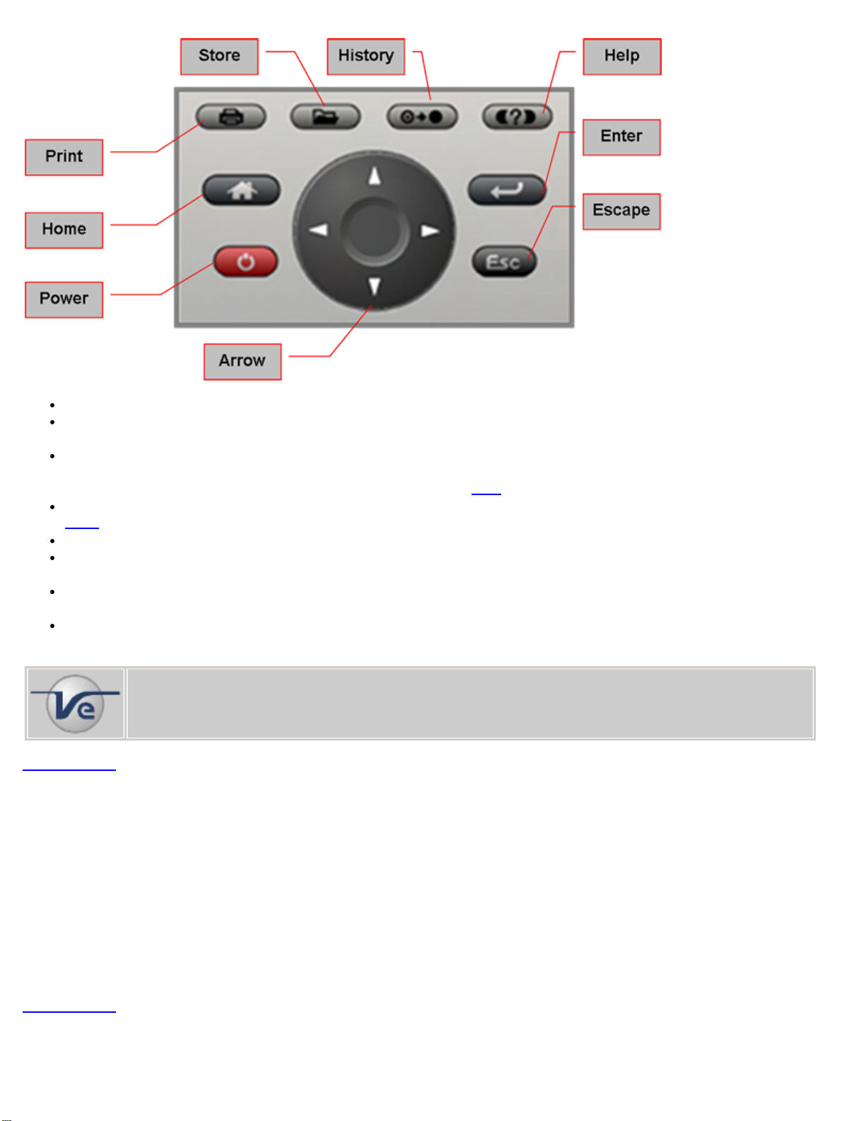
4.1 Keypad
The unit is powered on and off from the red key on the keypad area. In order to turn off the unit, press the power key for at least 2
seconds. If the unit is not responding, holding the power key down by more than 10 seconds will
The keypad includes the following keys:
LX100 e-Manual D07-00-019 Rev A01