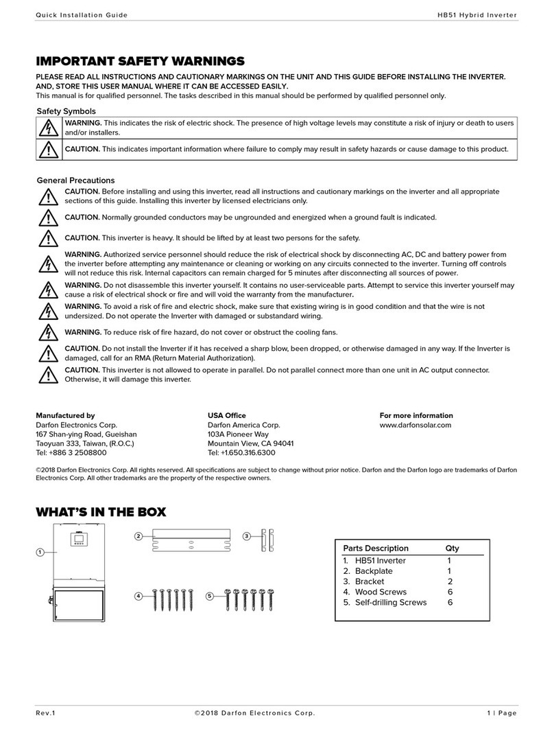
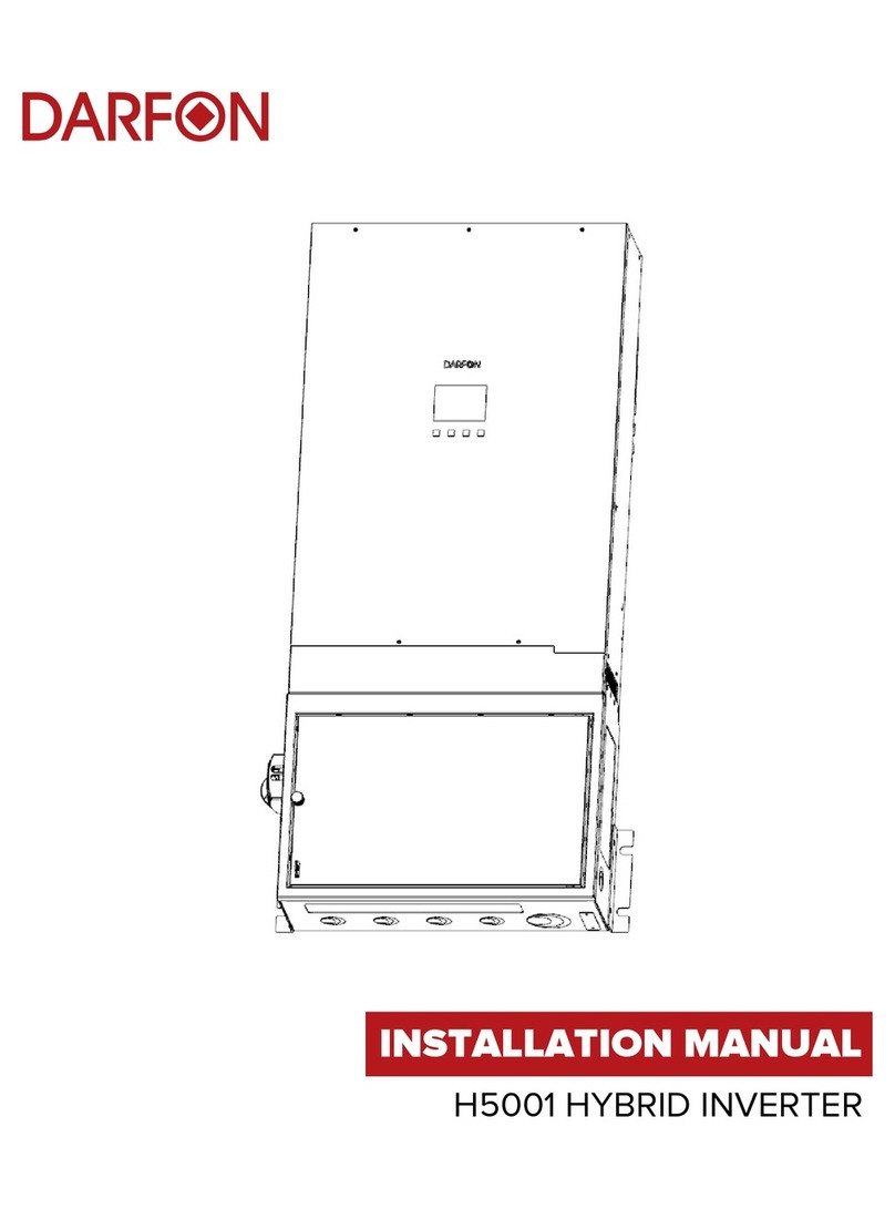
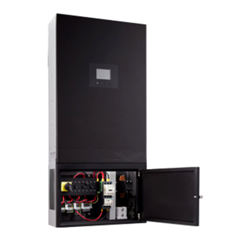
Darfon H5001 User manual

INSTALLATION MANUAL
H5001 HYBRID INVERTER

INSTALLATION MANUAL H5001 HYBRID INVERTER
REV.4 ©2022 DARFON ELECTRONICS CORP. 2| PAGE
TABLE OF CONTENTS
IMPORTANT SAFETY WARNINGS ..................................................................................................................... 3
WHAT’S IN THE BOX ............................................................................................................................................ 3
PRODUCT OVERVIEW .......................................................................................................................................... 4
Distribution Box........................................................................................................................................................4
Communication Ports.............................................................................................................................................4
Access Panel ............................................................................................................................................................4
Dead-Front Cover....................................................................................................................................................5
Mounting the Inverter.............................................................................................................................................5
OPERATIONAL MODES........................................................................................................................................ 6
SYSTEM DESIGN.....................................................................................................................................................7
Load Restrictions.....................................................................................................................................................7
Parallel Operation....................................................................................................................................................7
CONNECTIONS ...................................................................................................................................................... 8
System Types: Wiring Connection .....................................................................................................................8
Installing Conductors into the Terminal Blocks..............................................................................................8
Installing the Battery Conductors .......................................................................................................................8
Battery Charging Requirements..........................................................................................................................9
Communication Ports.............................................................................................................................................9
Access Panel ..........................................................................................................................................................10
TURNING THE SYSTEM ON/OFF .......................................................................................................................11
Turning On the System.........................................................................................................................................11
Turning Off the System.........................................................................................................................................11
OPERATION AND DISPLAY PANEL..................................................................................................................12
Display Overview...................................................................................................................................................12
Changing the Mode of Operation..................................................................................................................... 13
Setting the Battery Type......................................................................................................................................13
APPENDIX A: MAINTENANCE ...........................................................................................................................14
Cleaning ...................................................................................................................................................................14
Distribution Box Wiring Diagram.......................................................................................................................14
Error and Warning Definition..............................................................................................................................15
APPENDIX B: SPECIFICATIONS ........................................................................................................................ 17
APPENDIX C: CURRENT SENSOR [SOLD SEPARATELY] ............................................................................18
Wiring the Current Sensor ..................................................................................................................................18
APPENDIX D: EMERGENCY SHUTDOWN BUTTON [SOLD SEPARATELY].............................................19
Wiring the Emergency Shutdown Button to the Inverter...........................................................................19
Testing the Emergency Button.........................................................................................................................20
Resetting the Emergency Button.....................................................................................................................20
Troubleshooting....................................................................................................................................................20

INSTALLATION MANUAL H5001 HYBRID INVERTER
REV.4 ©2022 DARFON ELECTRONICS CORP. 3| PAGE
IMPORTANT SAFETY WARNINGS
Please read all instructions and cautionary markings on the unit and this manual before using the inverter. And, Store this
user manual where it can be accessed easily.
This manual is for qualified personnel. The tasks described in this manual may be performed by qualified personnel only.
Safety Symbols
WARNING. This indicates the risk of electric shock. The presence of high voltage levels may constitute a risk of injury or death to users
and/or installers.
CAUTION. This indicates information where failure to comply may result in safety hazards or cause damage to this product.
General Precautions
CAUTION. Before installing and using this inverter, read all instructions and cautionary markings on the inverter and all appropriate
sections of this guide. Installing this inverter by licensed electricians only.
CAUTION. Normally grounded conductors may be ungrounded and energized when a ground fault is indicated.
CAUTION. This inverter is heavy. It should be lifted by at least two persons for the safety.
WARNING. Authorized service personnel should reduce the risk of electrical shock by disconnecting AC, DC and battery power from
the inverter before attempting any maintenance or cleaning or working on any circuits connected to the inverter. Turning off controls
will not reduce this risk. Internal capacitors can remain charged for 5 minutes after disconnecting all sources of power.
WARNING. Do not disassemble this inverter yourself. It contains no user-serviceable parts. Attempt to service this inverter yourself may
cause a risk of electrical shock or fire and will void the warranty from the manufacturer.
WARNING. To avoid a risk of fire and electric shock, make sure that existing wiring is in good condition and that the wire is not
undersized. Do not operate the Inverter with damaged or substandard wiring.
CAUTION. To reduce risk of fire hazard, do not cover or obstruct the cooling fan.
CAUTION. Do not operate the Inverter if it has received a sharp blow, been dropped, or otherwise damaged in any way. If the Inverter
is damaged, call for an RMA (Return Material Authorization).
CAUTION. System design and installation must follow electrical specifications. Improper applications or misuse of the product may
damage the product and void the warranty.
CAUTION. Damages or malfunctions due to misuse, abuse, negligence, power surges, fire, natural disasters, pests, direct exposure to
sea water, force majeure, or other unforeseeable circumstances outside the range of influence of Darfon are not covered under
warranty.
WHAT’S IN THE BOX
1 2
5 6 7 8
3 4
Parts Description Qty
1. H5001 Inverter 1
2. Backplate 1
3. Wood Screws 6
4. Self-Drilling Screws 6
5. Brackets 2

INSTALLATION MANUAL H5001 HYBRID INVERTER
REV.4 ©2022 DARFON ELECTRONICS CORP. 4| PAGE
PRODUCT OVERVIEW
Distribution Box
Communication Ports
PORT
FUNCTION
RJ45
For External Display
RJ12 (x2)
For Parallel (Stacking) Function
RS485 S
For Data Logger
Dip Switches
For Long Distance RS485 Communication
RS485 M
For Battery BMS
RS-485 PIN DEFINITIONS
RS485 S
RS485 M
1
2
3
4
1
2
3
4
D+
D-
D+
D-
D+
D-
D+
D-
Access Panel
COMPONENT
FUNCTION
Piston Breakers
For Over Current Protection of Grid L1 & L2
Dip Switches
For Firmware Update
Jumpers
For Firmware Update
USB B
For Computer Connection
Communication
Ports
P
ower
S
witch
Battery
Breaker
Positive
Battery
Terminal
Negative
Battery
Terminal
Aux. Terminal
Load Terminal
Grid Terminal
PV Terminal
Load
Selection
Breakers
AUX GEN
Board
Grid Breaker
PV Disconnect
RJ12 RS485 S RS485 MRJ45
Dip Switches
Piston Breakers
Jumpers
USB B
Dip Switches
(Not on All Inverters)
Distribution Box
Access Panel
Cooling Fans
25mm (1.0in)
514mm (20.2in)
990 mm
(39.0in)
181mm (7.1in) 150mm (5.9in)
Top
Front
Bottom
Righ t
Left

INSTALLATION MANUAL H5001 HYBRID INVERTER
REV.4 ©2022 DARFON ELECTRONICS CORP. 5| PAGE
Dead-Front Cover
Notes
The dead-front cover must be
removed when making or modifying
connections in the distribution box,
and reinstalled when connections
have been completed.
To remove the dead-front cover, use
the following steps.
Reverse the steps to reinstall the
dead-front cover.
Remove the screws from the dead-
front cover.
Pull off the dead-front cover.
Mounting the Inverter
Notes
The unit cannot be mounted on flammable construction materials.
Allow 20cm (8in) of clearance to the sides and 50cm (20in) to the top and bottom of the unit for
proper air circulation to dissipate heat.
The unit has an IP20 protection rating and a PD2 Pollution Degree rating. The unit is for indoor
applications only and must be mounted in a protected area that is dry, free of excessive dust and
has adequate air flow.
CAUTION. The inverter is heavy (87lb/40kg). Mounting should be handled by two people.
Do not place any additional weight onto the inverter.
Mounting Dimensions
Wall Types
Stud: The inverter will need to be mounted to the wall using Unistrut. The Unistrut must be secured
to two studs in the wall. There should be two rows of Unistrut installed: one for the backplate and
the other for the side brackets.
Solid: Use the backplate and mounting dimensions to mark for screw locations.
Mount the backplate onto the wall.
Install the brackets the inverter.
Hang the
inverter onto
the backplate.
Secure the brackets to the wall. Note: Screw can go into either top or bottom slot of the bracket.
197mm
(7.8in)
237mm
(9.3in)
394mm (15.5in)
475mm
(18.7in)
605mm
(23.8 in)
90mm
(3.5in)
30mm
(1.2in)

INSTALLATION MANUAL H5001 HYBRID INVERTER
REV.4 ©2022 DARFON ELECTRONICS CORP. 6| PAGE
OPERATIONAL MODES
Mode Definitions
There are eight modes of operation: Back-up, Residential, Back-up w/o Feed-in, Residential w/o Feed-in, TOU w/o Batt. Feed-in,
TOU w/ Batt. Feed-in, string inverter and remote control. Each mode assumes a set of conditions and prioritizes the
consumption of PV, Grid or batteries accordingly to optimize energy flow.
Note: The default feed-in power for modes 5 and 6 is 3000W.
*On-Grid Battery DOD listed are default values. Value can be change to be between 10 and 60%.
PRESET MODES
DESCRIPTION
1. Back-Up
Keep the battery full and discharge only in cases of power outages
2. Residential
Self-consume from PV and battery first before the Grid
3. Back-Up Without Feed-in
Same as Back-up mode except power will not feed back to the Grid
4. Residential Without Feed-in
Same as Residential mode except power will not feed back to the Grid
5. Time Of Use
Low electricity cost
Operate as Back-up mode
High electricity cost
Operate as Residential mode
6. Time Of Use With
Battery Feed-In
Low electricity cost
Operate as Back-up mode
High electricity cost
Operate as Residential mode and will feed-in constant power back to the
Grid
7. String Inverter
Works as string inverter. Battery is disable.
8. Remote Control
Output and input power can be controlled through communication.
PRESET MODES PV USE
PRIORITY
LOAD
PRIORITY
CHARGE
FROM
FEED GRID
FROM
BATTERY
DOD
Load Batt. Grid PV Grid
Batt. PV Grid PV
Batt.
(No PV)
On-
Grid*
Off-
Grid
1. Back-Up
2
1
3
1
2
3
Ye s
Ye s
Ye s
No
40%
0%
2. Residential
1
2
3
1
3
2
Ye s
No
Ye s
No
40%
0%
3. Back-Up Without Feed-in
2
1
-
1
2
3
Ye s
Ye s
No
No
40%
0%
4. Residential Without Feed-in
1
2
-
1
3
2
Ye s
No
No
No
40%
0%
5. Time Of Use
Low electricity cost
2
1
3
1
2
3
Ye s
Ye s
Ye s
No
40%
0%
High electricity cost
1
2
3
1
3
2
Ye s
No
Ye s
No
40%
0%
6. Time Of Use With
Battery Feed-In
Low electricity cost
2
1
3
1
2
3
Ye s
Ye s
Ye s
Ye s
40%
0%
High electricity cost
1
3
2
1
3
2
Ye s
No
Ye s
Ye s
40%
0%
7. String Inverter
1
-
2
1
2
-
-
-
Ye s
-
-
-
8. Remote Control
Remote controlled
Ye s
Ye s
Ye s
Ye s
40%
0%

INSTALLATION MANUAL H5001 HYBRID INVERTER
REV.4 ©2022 DARFON ELECTRONICS CORP. 7| PAGE
SYSTEM DESIGN
Load Restrictions
Determining which loads the inverter will support is tricky. Having a good understanding of the system owner’s load usage is
key in configuring the load correctly. If the load is not configured correctly, it will constantly trip the inverter and produce an
overload error. The system will display an overload error when:
The continuous power required by the load exceeds the inverter specifications. When the grid is present, the continuous load
cannot exceed 7kW. When grid absent, the continuous load cannot exceed 5.5kW.
To ensure the load does not exceed the inverter’s continuous, analyze the system owner’s list of essential loads. Note which
hours each load will be running and make sure the total power used per hour does not exceed the inverter limits (7kW with
grid, 5.5kW without grid). Below is an example power usage during a 24-hour period.
Note: Loads should be configured in a way that the system owner can easily limit their load to 5.5kW when there are utility outages.
Equipment with large inrush current cause power surges that exceeds the inverter specifications. When the grid is present,
the inverter can accept power surges up to 7.5kW for 30 seconds. When the grid is absent, the inverter can accept power
surges up to 7.5kW, 6.5kW and 5.5kW for 1, 5 and 40 seconds, respectively.
It is important to know the inrush current of major appliances and equipment. Equipment with motors, such as water pumps,
will have a large inrush upon startup. Soft start devices should be installed to limit the power surges of any equipment with
large inrush currents.
Parallel Operation
Up to 3 H5001 can be connected in parallel. Each H5001 has its own charging
capability and can be controlled to work together, so you can incrementally add
power and storage in parallel at the same time. This makes designing and
configuring sites with larger demands easier.
Note: The installation of a parallel versus a single inverter system is different. To install a
parallel system, refer to the H5001 Parallel Installation Guide.
0
1
2
3
4
5
6
7
12AM 1AM 2AM 3AM 4AM 5AM 6AM 7AM 8AM 9AM 10AM 11AM 12PM 1PM 2PM 3PM 4PM 5PM 6PM 7PM 8PM 9PM 10PM 11PM
Stove
Med Equip
Lights
Fridge
TV
Water Heater
Oven
Sump Pump
Legend
1x H5001
2x H5001
3x H5001
Max. AC Load Off-Grid
5.5kW
8.8kW
13.2kW
Max. AC Load On-Grid
7kW
14kW
21kW
Note:
Battery Cont. Discharge Power > Max. AC Load Off-Grid

INSTALLATION MANUAL H5001 HYBRID INVERTER
REV.4 ©2022 DARFON ELECTRONICS CORP. 8| PAGE
CONNECTIONS
Notes
Order of wire connections should be Ground, N, L1, L2.
Connect AC wires according to the labels on the terminal block or your system type.
Connect PV wires into the inverter before connecting them to the PV panels.
It is recommended to install surge protection between the modules and the inverter.
This will reduce the risk of damage to the inverter due to surge.
Wire/Cable Requirements
PV
GRID
LOAD
BATTERY
Size
12 AWG
8 AWG
10 AWG
3 AWG
Te m p .
> 105°C
> 105°C
> 105°C
Length
--
--
--
< 3m
Strip 15mm(0.6in) off wires/cables.
PV Restrictions
MAX POWER
CURRENT
MPPT
PV1
3.25kW
13A
250 - 430VDC
PV2
3.25kW
13A
250 - 430VDC
WARNINGS
Make sure the circuit breaker is off before making or modifying any connections.
To prevent the risk of electric shock, make sure the ground wire is properly earthed
before operating this unit whether the grid is connected or not.
To reduce the risk of injury, use the recommended wire/cable size.
Only install monocrystalline or polycrystalline PV modules with Class A rating. Do not
use PV modules with potential leakage current. (e.g., non-grounded PV modules can
leak current to the inverter).
Do not exceed the maximum PV input voltage, doing so can damage the inverter.
Do not apply antioxidant substance on battery terminals connections are made.
System Types: Wiring Connection
Installing Conductors into the Terminal Blocks
Push a screwdriver into terminal.
Insert the wire into the terminal.
Remove the screwdriver.
Installing the Battery Conductors
Crimp or bolt ring lugs to the battery
cables.
Connect the red cable to the positive
(+) battery terminal.
Connect the black cable to the
negative (-) battery terminal.

INSTALLATION MANUAL H5001 HYBRID INVERTER
REV.4 ©2022 DARFON ELECTRONICS CORP. 9| PAGE
Battery Charging Requirements
The default charging parameters are shown below. Use this as a reference to make sure the battery selected is compatible with
the inverter. It is recommended that you use a deep cycle battery when the mode of operation is not set as one of the two back-
up modes.
PARAMETERS
LEAD-ACID BATTERY (DEFAULT VALUES)
LITHIUM BATTERIES (DEFAULT VALUES)
Max. Current
60A
60A
Float Voltage
54.4Vdc
N/A
Bulk Voltage
56.4Vdc
Darfon B05LM LMNC: 57.4Vdc
Panasonic DCB-105ZK LMNC : 52Vdc
Darfon B10LF/B12LF LFP: 54.75Vdc
Darfon B09ULF/B14ULF LFP: 51.5Vdc
Charging
process
First - charging voltage increases to 56.4V.
Second- charging voltage will maintain at 56.4V until charging
current is down to 2A.
Third- goes to float voltage at 54.4V.
First – SOC voltage increases to bulk voltage.
Second - charging voltage will maintain until SOC is 99%.
Third- stop charging after 1 hour.
Communication Ports
The inverter has communication ports for data logger communication, battery communication, external display connection and
parallel operation. The ports are located inside the distribution box, on the top bulkhead panel.
PORT
FUNCTION
RJ45
For External Display. The inverter can only connect to external displays provided by Darfon.
RJ12 (x2)
For Parallel (Stacking) Function. Only inverters of the same model can be installed in parallel.
RS485 S
For Data Logger. Check Darfon website for compatible data logger models.
Dip
Switches
For Long Distance RS485 Communication. If the distance between the Data Logger and Hybrid inverter is greater than 50m,
then the termination resistor switch on the Hybrid should be switched ON. If the distance between the Data Logger and
Hybrid is less than 50m, then the termination resistor switch on Hybrid should be switched OFF.
RS485 M
For Battery BMS. The inverter can only communicate with lithium batteries listed in the “Battery Charging Requirements”
section. If installing with Lead Acid or other lithium batteries not listed, the inverter will not be able to communicate with the
battery and the battery type should be set as Lead Acid.
Bulk Voltage
Bulk Absorption Float
Voltage Current
Time
Float Voltage
Bulk Voltage
Bulk Absorption
Voltage Current
Time

INSTALLATION MANUAL H5001 HYBRID INVERTER
REV.4 ©2022 DARFON ELECTRONICS CORP. 10 | PAGE
Access Panel
The access panel is used to manually update the inverter’s firmware. The inverter’s firmware can typically be updated via the
internet and data logger.
Remove the screws on either side of the Access Panel.
Lift the Access Panel away from the inverter.
Under the Access Panel there, note the locations of the piston breakers, Dip Switches, Jumpers, and USB B port.
PORT
USAGE
NOTES
Piston
Breakers
For Over Current
Protection
There are three circuit breakers that protect the Grid path. One circuit breaker is in the
distribution box and is rated at 40A. The piston breakers are for Grid L1 & L2 and are rated at
40A. If the Grid is properly connected and the inverter displays warning code 55 (Grid is
disconnected), check all three circuit breakers.
Dip Switches
Update firmware
See Firmware SOP for more information.
Jumpers
Update firmware
See Firmware SOP for more information.
USB B Port
For Computer
Connection
Connects to a computer to update firmware or AP registry. See Firmware SOP or AP Tool User
Guide for more information.
Piston Breakers
Jumpers
USB B
Dip Switches
(Not on All Inverters)

INSTALLATION MANUAL H5001 HYBRID INVERTER
REV.4 ©2022 DARFON ELECTRONICS CORP. 11 | PAGE
TURNING THE SYSTEM ON/OFF
Turning On the System
Turn on the battery breaker if
batteries are connected.
Turn on the battery. Refer to the
battery’s instruction manual.
Turn on the grid breaker if grid is
connected.
Turn on the Power Switch.
Wait for system bootup, and the fans
to turn on plus 3 beeps.
Turn on the Load Breaker.
Turning Off the System
Turn on the bypass breaker.
Turn off the Power Switch.
Turn off grid breakers.
Turn off the battery. Refer to the
battery’s instruction manual.
Turn off the battery breaker.

INSTALLATION MANUAL H5001 HYBRID INVERTER
REV.4 ©2022 DARFON ELECTRONICS CORP. 12 | PAGE
OPERATION AND DISPLAY PANEL
Display Overview
POWER FLOWS PAGE
POWER INFORMATION PAGE
SYSTEM SETTINGS PAGE
Enters System Settings
page or confirms selection.
Exits setting mode.
Previous page, previous
item or decrease number.
ICON
DESCRIPTION
Represents the PV Array
Represents the Battery Pack
Represents the Utility
Represents the Load
Represents the Hybrid Inverter
Indicates the Connection to a PC
Indicates the Error and error codes
Indicates an overload has occurred
Represents the System Mode Setting
Represents the System Time Setting
Represents the System Information
Current Time

INSTALLATION MANUAL H5001 HYBRID INVERTER
REV.4 ©2022 DARFON ELECTRONICS CORP. 13 | PAGE
Changing the Mode of Operation
In System Setting page, press the
key twice.
Use the or keys to toggle
between modes and to select.
MODES OF OPERATION
Back-Up
Residential
Back-Up Without Feed-In
Residential Without Feed-In
Time Of Use
Time Of Use With Battery Feed In
String Inverter
Remote Control
(TOU Modes) Enter “High Price
Duration” in 24-hour notation. Use
the or keys to adjust each
digit, and use the key to set it.
When done, press the key. You
will see a message stating the
settings are being updated.
When you see “Setting OK!!”
message, press any key.
Manually restart the inverter using the
Power Switch.
Setting the Battery Type
In the System Setting Page, press
to enter the page and select to
select Battery Type.
Use the or keys to select
Battery Type and to select it.
Use the or keys to toggle
between the battery types and press
to select it.
BATTERY TYPE
None
Lead-Acid
GC
Darfon LNMC
Panasonic
Darfon LFP
You will see a message stating the
settings are being updated.
When you see “Setting OK!!”
message, press any key.
Manually restart the inverter using the
Power Switch.

INSTALLATION MANUAL H5001 HYBRID INVERTER
REV.4 ©2022 DARFON ELECTRONICS CORP. 14 | PAGE
APPENDIX A: MAINTENANCE
Cleaning
Preform the following maintenance annually or more often if the site requires it to ensure proper operation.
•Clean this inverter, during the cool time of the day, whenever it is visibly dirty.
•Before cleaning this inverter, make sure to turn off all the breakers (AC, battery and PV).
•Ensure all connectors of this inverter are clean.
•Periodically inspect the system to make sure that all wires and supports are securely fastened in place.
CAUTION. There are no user-replaceable parts inside the inverter. Do not attempt to service the unit yourself.
Distribution Box Wiring Diagram
When replacing breakers or wires in the distribution box the following rules must be observed: (1) all AC breakers must be sized
for 40A or less, and (2) all wiring must be sized for 40A or more. The following diagram shows how the distribution box is
electrically connected to the hybrid inverter.
NOTES:
The H5001 has L1 and L2 connections for two AC input sources, although it can only accept one source at a time. The H5001 has separate
neutral connections for grid input, generator input and output. These are electrically common. The distribution box is both an input conduit
box and an AC load center.
The distribution box also contains maintenance transfer switches (load selection breaker). Maintenance transfer switching assemblies allows
for the inverter to be taken offline if necessary without shutting the entire system down. These assemblies include an interlock mechanism
that isolates the AC Lines from each other.
Generator function is optional, if need please contact your Darfon representative to buy generator kits. Generator application schematic
please refer to generator user manual.

INSTALLATION MANUAL H5001 HYBRID INVERTER
REV.4 ©2022 DARFON ELECTRONICS CORP. 15 | PAGE
Error and Warning Definition
On the Power Flows Page, the icon will flash when there is an error. Below are the error codes and their solutions.
CODE
FAULT EV EN T
ALARM
ICON
SOLUTION
01
DC bus voltage exceeds the upper
threshold
None
1. Turn off the inverter.
2. Make sure the PV terminal are not used, and DC Disconnect is off.
3. If Grid is absent, disconnect any grid-tied inverter from to the load terminal.
4. Turn on the inverter. If the error remains, contact your installer.
02
Arc occurs on PV
None
Reboot the inverter. If the error remains, contact your installer.
03
DC bus voltage falls below the lower
threshold
None
1. Turn off the inverter.
2. Measure the voltage at the battery and at the cabling above and below the
battery disconnect to make sure voltage is within 44 to 58Vdc.
3. If the voltages are in range, check if the battery went into protection mode.
4. Turn on the inverter. If the error remains, contact your installer.
04
Parallel setting is not correct
None
1. Check the parallel setting and mode setting.
2. Check the communication cable between stacking system.
3.
Reboot the inverter. If the error remains, contact your installer.
05
Battery discharging current exceeds
the upper threshold
On: 1s
Off: 1s
1. Turn off the inverter.
2. Make sure the Grid, Load and Battery terminals are wired properly.
3. Turn on the inverter. If the error remains, contact your installer.
06
Battery charging current exceeds the
upper threshold
On: 1s
Off: 1s
07
Short circuit on PV1 input
None
Reboot the inverter. If the error remains, have your installer check the PV array for
short circuits.
08
Short circuit on PV2 input
None
09
Short circuit on AC output
Continuous
1. Turn off the inverter.
2. Turn off the load breaker.
3. Make sure L1, L2 and N on the load circuit are not shorted.
4. Turn on the inverter. If the error remains, contact your installer.
10 Leakage current CT fault None 1.
Turn off the inverter.
2. If DC Disconnect is on, turn it off. Then turn on the inverter. If the error remains,
turn off the inverter again.
3. Turn off the battery breaker. Check the battery and the battery cablers for leaking
current. If found, contact your installer.
4. Turn off the load breaker. Check all appliances on the essential load for leaking
current. If found, unplug the appliance safely. Then turn on the inverter.
5. If the error remains, turn off the Utility and the inverter’s Grid breaker. Then
measure the Grid and make sure the impedance of L1, L2 and N relative to
ground and to each other should be an open circuit.
6. Reboot the inverter. If the error remains, contact your installer.
11
DC/DC Current Sensor fault
None
Reboot the inverter. If the error remains, contact your installer.
14
EEPROM read failure
None
15
Communication with main & secondary
controllers are interrupted
None
16
Over temperature fault
[The internal temperature is too high]
On: 1s
Off: 1s
1. Make sure the inverter is properly ventilated by removing any obstruction around
the vents.
2. Make sure the fans are working.
3. Turn off the inverter, let it cool down for 10 minutes, then turn it back on.
4.
If the error remains, contact your installer.
17
PV input voltage exceeds the upper
threshold
None
1. If the PV V
OC
is higher than 500VDC, contact your installer.
2. If the PV VOC is less than 500VDC, turn off the inverter and restart it after 5
seconds. If the error remains, contact your installer.
18
Over power protection
[The Grid/ Load power has been over
7.5kW for 30s.]
On: 0.25s
Off: 0.75s
1. Turn off the inverter.
2. Make sure the load is lower than 5kW
3. Turn on the inverter. If the error remains, contact your installer.
19
PV insulation resistance is too low
None
1. Turn off the DC Disconnect.
2. Check if the impedance between positive and negative poles to the ground is
greater than 1MΩ.
3. If the impedance is lower than 1MΩ, contact your installer.
20
Battery charging voltage is too high
None
1. Turn off the inverter.
2. Make sure the connection between battery and inverter has firm and solid
contact.
3. Make sure the battery voltage is within manufacturer’s specifications.
4.
Turn on the inverter. If the error remains, contact your installer.
21
Fan fault
None
1. Reboot the inverter.
2. Make sure the fans are working. If the error remains, contact your installer.
22
Overload
[The load exceeds available output
power. This error will disappear once
load is in an acceptable range.]
On: 0.25s
Off: 0.75s
1. If an overload occurs for more than 40 seconds, the inverter will turn off the load
output for 30 seconds. If the inverter turns off the load output 3 times within a 5-
minute interval, the load output will be turned off indefinitely.
2. To turn the load output back on, reboot the inverter.
3. If overload error appears constantly, decrease the load.
23
PV input over power
None
1. Make sure your total PV does not exceed 6.5kW, and each string does not
exceed 3.25kW.
2. Reboot the inverter. If the error remains, contact your installer.

INSTALLATION MANUAL H5001 HYBRID INVERTER
REV.4 ©2022 DARFON ELECTRONICS CORP. 16 | PAGE
CODE
FAULT EV EN T
ALARM
ICON
SOLUTION
24
Battery type is wrong
None
1. Set the correct battery type according to the battery installed to the system.
2. Reboot the inverter. If the error remains, contact your installer.
Note: For third-party lithium batteries, battery type should be set as Lead Acid.
25
RCMU test fault
None
Reboot the inverter. If the error remains, contact your installer.
26
Model setting fault
None
Reboot the inverter. If the error remains, contact your installer.
27
Battery Voltage Drop
[Battery voltage dropped below 30V]
None
1. Check the battery BMS errors and the wiring.
2.
Reboot the inverter. If the error remains, contact your installer.
28
Battery wake up fault
[The system tried to wake up the
battery but failed.]
None
1. Turn off the inverter.
2. Check the battery voltage.
3. Check the battery breaker and wiring.
4. Check the battery communication cable.
5. Tur n on the inverter. If the error remains, contact your installer.
On the Power Flows Page, the icon will flash when there is a warning. Below are warning codes and their solutions.
CODE
WARNING
ICON
SOLUTION
53
Stacking Canbus communication error
1. Turn off the inverter.
2. Check the canbus communication cables.
3. Turn on the inverter. If error remains, contact your installer.
54
Power island
1. For warning 55. If the Utility is down, wait for it to come back on.
2. Reboot the inverter.
3. The inverter will wait for 5 minutes before attempting to connect to the Grid.
4. If the warning remains, contact your installer.
55
Grid is disconnected
56
Grid voltage exceeds the upper threshold
57
Grid voltage falls below the lower threshold
58
Grid frequency exceeds the upper threshold
59 Grid frequency falls below the lower threshold
61
Battery voltage is too low
[Battery voltage is less than 44V (lead-acid) or
SOC is lower than 10% (Lithium)]
Wait for the Grid or PV to charge the battery. Warning code will change to 62 once the battery
voltage is above 44V or the SOC is above 10%.
Note: Battery cannot be discharged, and system output can only come from the Grid.
62 Low battery SOC level
[The battery SOC is less than the battery
reserve]
Wait for the Grid or PV to charge the battery. Once the SOC reaches 20% above the battery
reserve, the warning will be cleared.
Notes:
If the Grid is absent, the battery can be discharged.
If the Grid is present, the battery can be discharged if SOC is above the battery reserve.
63
Battery is not detected
1. Turn off the inverter.
2. Make sure the battery is on.
3. Check battery connection for any loose wiring.
4. Turn on the inverter. If error message remains, contact your installer.
64
Inverter output OCP
1. Inverter output current exceeds the upper threshold.
2. Reboot the inverter. If error remains, contact your installer.
Alarm – On: 1s, Off: 1s
65
RS485 communication error
1. Turn off the inverter and check all communication wires.
2. Turn on the inverter. If error remains, contact your installer.
66
Output derated
[When system temperature is too high, the
output power has been derated.]
1. Make sure the inverter is properly ventilated and the fans are free of debris.
2. If possible, lower the load or ambient temperature.
Notes:
System output lowered to 60% when the system temperature is higher than 85°C.
System output lowered to 80% when the system temperature is higher than 80°C.
System output restored to 100% when the system temperature is lower than 70°C.
67
Off Grid Operation
Grid is present, but system is in off-grid mode via remote command.
68 Peak Shaving Over Power
Grid power usage has reached the Peak Shaving Power threshold.
69
Generator mode
The grid is not present, and the inverter is receiving power from the generator.
70
Generator Reverse Feed
Power is feeding back to the generator. If the inverter is setup to have remote control over the
generator, the inverter will turn off the generator.
71
Battery voltage Inconsistent
Battery voltage measured by the inverter is not consistent with the BMS value.

INSTALLATION MANUAL H5001 HYBRID INVERTER
REV.4 ©2022 DARFON ELECTRONICS CORP. 17 | PAGE
APPENDIX B: SPECIFICATIONS
SOLAR DC INPUT
Nominal Power
6500W
Operation / MPPT Voltage Range
120 to 500VDC / 250 to 430VDC
Minimum Start Voltage
150VDC
Maximum Input Current
13A / 13A (two string input)
AC OUTPUT TO LOAD
WITH GRID ABSENT
WITH GRID PRESENT
Output Power (Continuous) @ 25°C
5500W
7000W
Overload 40/20/5/1 sec @ 25°C and 240V
5500/--/6500/7500W
--/7500/--/--W
Overload 40/5/1 sec @ 25°C and 120V
2750/3250/3750W
NA
Rated Output Current (RMS)
23A (@120V and 240V)
29A (@120V and 240V)
Output Frequency (Auto Sensing)
50/60Hz
Output Voltage and Accuracy
L-N: 120V ± 3%; L-L: 240V ± 3%
Output Voltage Limits
L-L: 180 to 280V (240V Nominal)
Total Harmonic Distortion (THD)
< 5% at rated power
Power Factor
>99%
AC INPUT FROM GRID
Automatic Transfer Power Rating / Typical Transfer Time
7000W / 20ms
Input Voltage Limits (Bypass)
L-L: 180 to 280V (240V nominal)
Input Frequency Range (Bypass)
45 to 54.9Hz / 55 to 65 Hz
AC OUTPUT TO GRID (GRID SUPPORT)
Output Power (Continuous) @ 25°C
5000W
Grid Sell Current Range ( Depending On Operation Mode)
0 to 24A (@240V)
Grid Sell Voltage Range
L-L: 211 to 264V ± 3.0V
Grid Sell Frequency Range
49.3 to 50.5Hz / 59.3 to 60.5Hz ± 0.05Hz
EFFICIENCY
Peak PV to Grid
96%
CEC weighted PV to Grid
95.5%
System Standby Power
20W
System Idle Power
< 8W
DC BATTERY CHARGER
Maximum Charge/Discharge Current
60A/150A
Output Voltage Range
44 to 58V (48V Nominal)
Compatible Battery Types
AGM, Gel, Li-ion, LiFePO4, Custom
Battery Bank Range
200 to 600Ah (Suggested)
GENERAL SPECIFICATIONS
Product weight
39.4 kg (86.8lb)
Product dimensions (H x W x D)
990x 448 x 150mm (39 x 17.6 x 5.9in)
Protection Rating
NEMA Type 1 Indoor/IP20
Temperature
Operating: -20 to 50°C (-4 to 122°F), power derated > 40°C (104°F)
Min Startup: 0°C (32°F)
Storage: -25 to 70°C(-13 to 158°F)
Compliances
UL1741SA, CSA CS22.2, IEEE 1547A, IEEE 1547.1, FCC Class B, HECO

INSTALLATION MANUAL H5001 HYBRID INVERTER
REV.4 ©2022 DARFON ELECTRONICS CORP. 18 | PAGE
Notes
Reversing the direction of the polarity will give an incorrect reading.
CT1 must connect to L1 and CT2 must connect to L2. Mismatching the
connections will give an incorrect reading.
APPENDIX C: CURRENT SENSOR [SOLD SEPARATELY]
WARNING. To prevent the risk of electric shock, do not clamp CT
sensors onto L1 nor L2 before connecting the 4-pin terminal
block in the inverter’s AUX GEN board.
Wiring the Current Sensor
Make sure inverter’s hardware version is 2 or above. CTs cannot be installed with inverter hardware version 1.
Connect the 4-pin terminal block into the inverter’s AUX GEN board.
Clamp CT1 onto L1 and CT2 onto L2. Make sure the polarity is in the correct direction. The arrow should always point towards
the source.
CT Sensor Rating
Choose the correct CT sensor rating based on the
rating of the site’s main panel.
Main Panel Rating
CT Sensor Rating
CT Sensor Part No.
≤ 300A
300A
JQ.Q3C31.D01
> 300A
600A
JQ.Q3C31.D03

INSTALLATION MANUAL H5001 HYBRID INVERTER
REV.4 ©2022 DARFON ELECTRONICS CORP. 19 | PAGE
APPENDIX D: EMERGENCY SHUTDOWN BUTTON [SOLD SEPARATELY]
Wiring the Emergency Shutdown Button to the Inverter
Turn off the system.
Check the AUX GEN board version. The board will either be green or yellow. If it is yellow, skip to step 5.
Remove the access panel and locate the emergency port.
Insert the 2-pin connector from the emergency button into
the emergency port, then skip to step 7.
Remove the white 2-pin connector from the emergency
button by disconnecting the terminal blocks.
On the yellow AUX GEN board, connect the terminal block into RLY Input (pins 6 and 7). If a 7-pin terminal block is already
there, remove the red and white wire from the 2-pin terminal block and insert it into pins 6 and 7.
Test the emergency shutdown button.

INSTALLATION MANUAL H5001 HYBRID INVERTER
REV.4 ©2022 DARFON ELECTRONICS CORP. 20 | PAGE
Testing the Emergency Button
Turn on the system and wait for it to bootup.
Press the emergency shutdown button. The inverter will immediately shut down.
Note: If the inverter did not shutdown. Check the wiring and make sure the connectors are seated properly. Check for
conductor continuity as well.
Reset the emergency button.
Resetting the Emergency Button
Remove the safety cover. While pressing the button down,
pull the safety cover away.
Reset the emergency button. Rotate button clockwise. The
button will pop back to the starting position.
Reset the safety cover. Push the top section of the safety
cover onto the base until it clicks into place.
Put the safety cover back over the button. Be careful not
accidentally press the button.
Troubleshooting
If the inverter shuts down immediately after it is turned on, the emergency button may have been set incorrectly. Open the
emergency button and check the wiring.
Unscrew the four screws and pull the base apart.
Confirm the wires are connected to a terminal labelled
“NO”. Rewire to a “NO” terminal if the wiring is incorrect.
Other manuals for H5001
2
Table of contents
Other Darfon Inverter manuals

Darfon
Darfon HB51 User manual

Darfon
Darfon H5000 User manual

Darfon
Darfon G640 User manual

Darfon
Darfon MIG240 User manual

Darfon
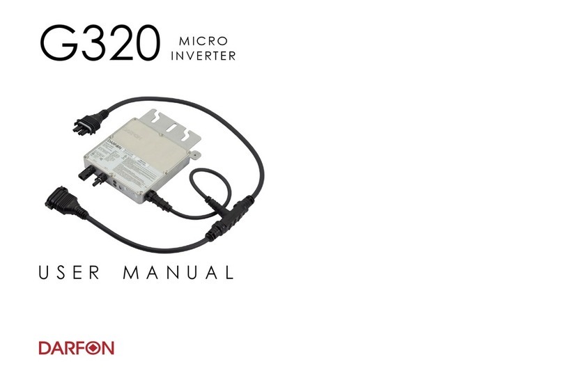
Darfon G320 User manual

Darfon
Darfon H5001 User manual

Darfon
Darfon MIG240UL00 User manual

Darfon
Darfon PVI5000 User manual

Darfon
Darfon H5001 User manual

Darfon
Darfon MIG300 User manual