DAS DL-300E User manual

1
DL-300E
DOWNLOADABLE CONTROL COMMUNICATOR
INSTALLATION MANUAL
TABLE OF CONTENTS
1. GENERAL DESCRIPTION P.2
2. STANDARD AND OPTICAL PARTS LIST P.2
3. FEATURE DEFINITIONS P.3
4. TERMINAL DRAWING AND SPECIAL NOTES P.4
5. TERMINAL DESCRIPTION P.5
6. PROGRAMMING PROCEDURES & EXAMPLES P.6-7
7. SPECIAL APPLICATION NOTES P.8
8. USERS 1-15 ARM/DISARM CODE ENABLING P.9
9. PHONE NUMBER & ACCOUNT CODE PROGRAMMING P.10-11
10. COMMUNICATOR FORMAT SELECTIONS P.11
11. AVAILABLE SECTOR TYPES P.14
12. PROGRAMMING THE AUXILIARY OUTPUTS P.18
13. PROGRAMMING FOR PARTITIONS P.22
14. REPORTING USER NUMBERS FOR VARIOUS FORMATS P.26
15. USERS 16-32 ARM/DISARM CODE ENABLING P.29
16. LOCATIONS ACCESSIBLE THROUGH DOWNLOADING ONLY P.33
17. PROGRAMMIG WORKSHEETS P.34-44
18. APPENDIX 1- PROGRAMMING CONTACT I.D. FORMAT P.45
19. APPENDIX 2- PROGRAMMING SIA FORMAT P.46
20. APPENDIX 3- PROGRAMMING FORMAT OVERRIDES P.47-48
21. SPECIFICATIONS & WARRANTY P.50
DIRECT ALARM SUPPLIES, CONDELL PARK NSW
SERVICE / TECHNICAL (02) 97092811 or 1 800 252213
SALES
NSW VIC QLD SA WA
(02) 9647 2011 (03) 9562 7622 (07) 3252 5512 (08) 8371 1683 (08) 9345 3644
(02) 9698 9698 (03) 9383 2066
TAS DISTRIBUTOR – GHE
(03) 6331 6533 (03) 6234 2233

2
Standard Parts List
DL-300E
INSTALLATION
MANUAL
General
Description
The DAS DL-300E is a versatile 16 expandable to 32 zone up/downloadable security control with a built-in digital communicator. Its
microcomputer design gives some of the most versatile, yet easy to use features available for most security applications today.
Some of the features of the DL-300E include; Paritionable up to four separate systems, dual reporting, Partial Mode (for at home
monitoring), 30 user codes, internal log, time restriction options for user codes, dynamic battery test, domestic dialing format, plus
many more. Each of the 32 zones can be programmed to be one of nine different types including 24 Hour, Handover, Day Zone,
and secondary entry. The system can be used with LCD or LED code pads, keyswitches, or radio remote arming. Each zone is
individually annunciated and can be isolated from the code pad if so enabled. See page 14 for a description of all zone types. Read
the OPERATOR'S MANUAL before you begin the installation for the best overall description of how the DL-300E functions. After
installation of the security system, complete the information on page 1 of the operator's manual and explain the system operation to
all security system owners/operators.
QUANTITY PARTS DESCRIPTION PART #
1MASTER CONTROL PANEL W/O CODE PAD FS4533
20 3K3 ½ WATT EOL RESISTORS EOL-33
1(4) WIRE LEAD FOR AUX OUTPUTS 8920
1INSTALLATION MANUAL IM-DL-300E
1OPERATORS MANUAL OM-DL-300E
OPTIONAL PARTS DESCRIPTION PART #
16 LED REMOTE CODE PAD FS4531
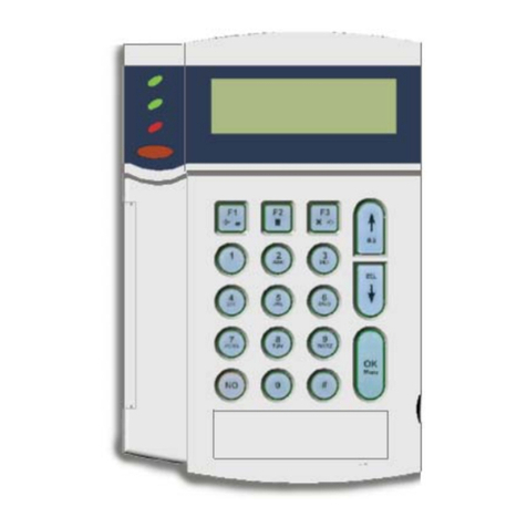
LCD ALPHA NUMERIC DISPLAY CODE PAD FS4534
AC POWER SUPPLY 16.5V 3 AMP PLUG PACK FS4426
SMART PROGRAMMER WITH LCD DISPLAY FS461 0
PROGRAMMER WITH DIGITAL NUMERIC DISPLAY FS4597
8 WAY RELAY OUTPUT MODULE FS4634
16 WAY VOLTAGE OUTPUT MODULE FS4614
16 WAY X-10 VOLTAGE OUTPUT MODULE FS4804
12 VOLT 6.5 AMP HOUR BATTERY FS4312
Optional Parts List
The following parts are available for use with the DL300E.

3
FEATURE DEFINITIONS
Partitions
-The DL-300E can be partitioned into a maximum of four separate systems with distinct reporting codes and user
codes per system. See page 23 for instructions.
Secondary Exit Delay
- Used most often for garage doors, this zone type is a second entry/exit delay that has its own
delay times, independent of the standard entry/exit delay zone.
Group Isolate
-Zones can be programmed to isolate as a group when the [*] digit is pressed during the exit delay. This
feature is enabled in Locations 155-170: Assigning Special Characteristics For Zones beginning on page 14 of this manual.
Partial Mode
-This unique low level arming allows you to remain inside your home and only arm areas that are not occupied.
For example, Night Arming.
Chime
-This lowest level of security can be enabled by zone (see page 15, Locations 171-186: Assigning Audible
Characteristics For Zones) to create a one second tone through the code pad sounder when the system is disarmed and a zone is
violated. If so programmed, this feature can be turned on and off by a one digit keypress programmed in Location 244: Assigning
The Chime Code on page 23 of this manual.
Auto Isolate Enable
-When enabled in locations 205, the DL-300E can be armed with zones violated, lacking a green
"Secure" light on the code pad. Under this condition, all zones that are not secure at the end of the exit delay will become isolated
All zones that become secured before the end of the exit delay will become active in the system.
Dialer Acknowledge Feature-
When enabled in location 212, a two second audible output of the siren or bell will
occur after a kissoff has been received by the control panel. I E. (When the system is fully armed and finished communication to the
base station.)
Dynamic Battery Test
-When enabled in locations 254-255, the DL-300E can be programmed to perform a dynamic
battery test for a selected duration, at a selected time.
Internal Event Log -
Up to 256 events can be stored in memory along with the date and time of the event. These
events can later be viewed through downloading, and/or sent to an on-site printer which can be connected to the DL-300E through
one of the available expansion devices.
Site Initiated Downloading
- The control panel can be programmed to automatically call the download software at a
specific time (also see location 622 on page 31).

4

5
TERMINAL DESCRIPTION
TERMINAL # DESCRIPTION
1Connect one side of zone 1 loop. Connect other side of loop to
common terminal 2. Open
or short causes alarm.
2Common (-) Terminal.
3Connect one side of zone 2 loop. Connect other side of loop to
common terminal 2. Open
or short causes alarm.
4-12 See Terminal Drawing and repeat the above sequence for zones 3
through 8.
13-14 Auxiliary power, regulated 12VDC. Maximum 700mA for all Auxiliary
power outputs.
15-26 See Terminal Drawing and continue above described hookup zones 9
through 16.
27-28 Auxiliary power, regulated 12VDC. Maximum 700mA for all Auxiliary
power outputs.
29 Earth Ground, connect to a cold water pipe, or 6 to 10 foot driven rod.
30-31 AC input, connect a 16.5V 50VA approved transformer.
32-33 Resettable 12VDC 250mA Aux power.(Memory reset and/or Smoke
detector power)
34-36 Form C programmable on board relay output. Tied to auxiliary output
#3.
37 Negative, provided as a convenience for relay connection.
38-39 Form A programmable on board relay output. Tied to auxiliary output
#4.
40-41 Siren driver output to speaker(s). Min speaker rating 30/40 watt at 4, 8,
or 16 ohms). See
page ? for connection diagram. When a 10/15 watt speaker is used,
connect one wire to
terminal 40 or 41 and the other wire to terminal 37.
42-45 Connect code pad wires as follows; Green to terminal 42, Yellow to
Terminal 43, Red to
terminal 44, and Black to terminal 45. Maximum run with 7/020 cable is
70 meters.
Maximum run with 14/020 cable is 120 meters. A maximum of 4 code
Pads may be
Connected.
Battery :Leads Connect to 12VDC lead acid rechargeable battery: Black(-) & Red(+).
Do not use a dry cell
battery.
FUSE DESCRIPTION
F1
C

6
PROGRAMMING
The DL-300E can be placed into the "Program" mode by use of the new FS4610 Smart Programmer, or the original FS4597
programmer or for code pad programming, by utilizing the FS4534 LCD code pad (the preferred method) or the FS4531 LEL
code pad. These methods are described below.
Using a
Programmer
The FS461 0 Smart Programmer has been designed to make programming of the DL-300E simpler as well as more efficient for users.
The FS4610 programmer features up to 4 resident standard programs to allow for separate system standardization. Plug the optional
model FS461 0 programmer into the 4-pin male outlet marked "program" on the DL-300E P.C. Board. We have also created a
method that allows owners of the original FS4597 programmer to use this programmer with the DL-300E. The FS4597 will program
all locations of the DL-300E but requires additional care for locations 400 and above. When the 400 location is reached, the two right
7 segment numeric displays will begin to flash on and off and the left side numeric display will change to "0". The flashing is a signal
to add a 4 to the left side number to determine which location you are now programming. For example, if you are in location 575,
the left (100's column) will be displaying a "1 ", the middle (10's column) will be flashing and displaying a "7", and the right (one's
column) will be flashing and displaying a "5". By adding a 4 to the "1" displayed in left column, it is determined that the location
number is 575.
Using The LCD Code
pad
The most straightforward method of code pad programming is to utilize the FS4534 LCD Code pad in the programming mode. To
access the programming mode enter [C] [0] [0], followed by the four digit "Go To Program" access code which is factory default [9]
[0] [5] [0] (this code can be reprogrammed), and follow the code pad prompts.
Using The LED Code
pad
The DL-300E can also be programmed by the standard binary method of code pad programming described below. However, with over
600 locations, this method will be difficult except for the most experienced programmer. When the FS4531 LED code pad is used for
programming, enter the factory default four digit "Go To Program" access code of [9] [7] [1 ] [3]. NOTE: The DL300E must be
disarmed to gain access to programming with this code. After entry of this code, the DL-300E will be in the "Program" mode, and the
yellow LED's will display the data in location 000. The data is displayed using a Binary system. With this system the yellow zone 1 LED
equals "1" when illuminated. The zone 2 LED equals "2" when illuminated. The zone 3 LED equals "4" when illuminated. The zone 4
LED equals "8" when illuminated. Thus if the data in location 000 is "9", the LED for zone 1 (=1) and zone 4 (=8) would be
illuminated. By adding the two values together, (1+8=9) you would determine that the data in location 000 is "9". If the data in
location 000 is "6", the LED or zone 2 (=2) and zone 3 (=4) would be added (2+4=6) indicating the data in that location to be "6". If
no LED's are illuminated, the location contains a "0". To advance from location 000 through 635, press the [#] key. To go to a specific
location, press the location number followed by the [#] key. The yellow LED's will then display the data in that location. Data is
changed by entering a number 0 to 15 followed by [*] (* = data enter). Review the examples in figure 1 on the following page.
Important Function
Codes
[9]-[5]-[O]-[#] When in the program mode, this function code can be used to write original factory default codes into the
DL-300E.
[9]-[3]-[0]-[#] This function code is used to exit the programming mode after it was accessed via the code pad
!!! IMPORTANT !!!
Before programming the DL-300E for the first time, enter the "Go To Program Code" [9][7][i ][3] from the code pad, followed by the
factory default function code [9][5][0][#]. The panel defaults will now match this installation manual and you may begin
programming the control panel. When using an optional plug-in programmer which automatically enters the programming mode, the
only entry necessary is [9][5][0][#] to load factory defaults.

7

8

9
Location 000-003: Programming The Master Arm/Disarm Code
Locations 000-003 contain master arm/disarm code (user number 1). Location 000 contains the first digit of the code; location '003
contains the fourth digit of the code. THE CODE MUST CONTAIN FOUR (4) DIGITS. The master code can then be used in the RUN
mode to enter arm/disarm codes 1-30. The factory default code is [i][2][3][4].
Location 004-055: Programming The Arm/Disarm Code For Users 2 Thru 14
Locations 004-055 contain the arm/disarm codes for users 2 thru 14. To program these codes, follow the instructions in the
paragraph above. To disable these codes, program a "15" (factory default) as the first digit of the code. These codes can be
changed in the RUN mode using the master code (refer to operator's manual).
Location 056-059: Programming The Arm/Disarm Code For User 15 (Duress Code)
Locations 056-059 contain the arm/disarm code for user number 15 (Duress Code). To program this code, follow the instructions in
the paragraph above. This code can be used as a duress code if so programmed in locations 320-323. Factory default for this code is
"15", disabled.
Location 060-063: Programming The "Go To Program" Access Code
Locations 060-063 contain the "Go To Program" access code. Location 060 Contains the first digit of the code and location 063
contains the fourth digit of the code. THE CODE MUST CONTAIN FOUR (4) DIGITS. With the DL-300E disarmed, the "Go To
Program" access code can be used to enter the program mode. To disable the "Go To Program" access code, program a "15" in
location 060. The factory default setting is [9][7][1 ][3]. NOTE: The first digit of this code should not match the Quick-Arm digit.
NOTE: If a "15" is programmed into location 60 to disable this code, programming can only be accessed through the downloading
software or with a plug in programmer.
Location 064-079: Users 1-15 Arm/Disarm Code Enable By Partition
PARTITIONED SYSTEMS
If partitions are utilized, codes may be assigned to a specific partition by using locations 064-079. This is done by disabling each
individual code (code 1 is location 064, code 15 is location 079) for each of the four partitions that code should not have access to.
Codes are selected by adding the binary equivalents for each partition together and placing that number in the proper location.
Partition One = 1, Partition Two = 2, Partition Three = 4, and Partition Four = 8. For example, if code 2 should only be valid for
Partition Four, program a "8" in location 065. If code 10 is valid for Partitions Two, Three, and Four, a "14" would be programmed in
location 073. Factory default is "15", code valid for all partitions.
VALUE PARTITION SELECTION VALUE PARTITION SELECTION
0
NO PARTITIONS ENABLED
8
ENABLES PARTITION 4
1ENABLES PARTITION 1 9ENABLES PARTITION 1 & 4
2ENABLES PARTITION 2 10 ENABLES PARTITION 2 & 4
3ENABLES PARTITION 1 & 2 11 ENABLES PARTITION 1, 2 & 4
4ENABLES PARTITION 3 12 ENABLES PARTITION 3 & 4
5ENABLES PARTITION 1 & 3 13 ENABLES PARTITION 1,3 & 4
6ENABLES PARTITION 2 & 3 14 ENABLES PARTITION 2, 3 & 4
7ENABLES PARTITION 1, 2 & 3 15 ENABLES PARTITION 1,2,3 & 4

10
NON-PARTITIONED
SYSTEMS
When partitioning is not being utilized, locations 064-079 can be used to control the arming and disarming authority of the
individual arm/disarm codes. A code can be given limited authority by programming a number from 1 to 15 in the corresponding
location for that code. Add the values in the table below that correspond to the desired arm/disarm characteristics, and program
the sum in the appropriate locations. -
VALUE AUTHORISATION LEVEL VALUE AUTHORISATION LEVEL
0NO AUTHORISATION LEVEL (USED
FOR AUXILIARY OUTPUT) 9REGULAR ARM/DISARM CODE
OPEN/CLOSE REPORTS BY USER
1REGULAR ARM/DISARM CODE 10 ARM ONLY AFTER CLOSING TIME
OPEN/CLOSE REPORTS BY USER
2ARM ONLY AFTER CLOSING TIME
NORMALLY REGULAR CODE,
CHANGE TO ARM ONLY CODE
AFTER THE CLOSING TIME, RESET AT
THE OPEN TIME
12 ARM ONLY CODE
OPEN/CLOSE REPORTS BY USER
4ARM ONLY CODE
Location 080-095: Programming Phone #1
Phone #1 is programmed in successive locations beginning with location 080. Delays of four seconds can be programmed at any point in
the phone number by programming a "13" in the appropriate location. If tone dialing is desired, program a "15" in the location where tone
dialing should begin. If the entire number should be tone dialing, program a "15" in location 080. Factory default is "14" in each location
and the phone number is not enabled. When using split or dual reporting, phone #1 always take priority over phone #2. A "14" indicates
the end of the phone number. EXAMPLE: Phone number 02
-7244211 with touch tone dialing would be entered as [1][5][*][#] [0][*][#]
[2)[*][#] [7][*][#] [2][*][#] (4][*][#] [4][*][#J [2][*][#] [1][*][#] [1][*][#] [14][*][#]. The "15" selects touch tone dialing, and the
"14" end the phone number.
Location 096-100: Programming The Account Code For Phone #1 (Or Partition One)
The account code sent when phone #1 is dialed is programmed in locations 096
-100.. If the account code is three digits long, use
locations 096 097, 098, and program a "0" in locations 099 and 100. If the account code is four digits long, program a "0" in location
100. If a zero "0" is part of an account code, it should be programmed as a "10". Program a "0" to indicate the end of the account code.
To make this account code the account code for "Partition One", see location 132. EXAMPLE: Account number of 2090 would be entered
as [2][*][#j [10][*][#] [9][*][#] [10][*][#] [0][*][#] (starting at location 96). Account code of 209 for low speed
Location 101: Communicator Format For Phone #1
Location 101 contains the communicator format used to transmit to the receiver connected to the phone #1. Consult the instructions for
your central station receiver to determine which format is compatible. Select a format from the 14 listed on page 10. If you require a
format other than those listed, review the override options described in locations 610
-615, to build the appropriate format. A "15" must
be programmed in location 101 in addition to the entries into locations 610-615 in order to create a special
format. If this location
contains a "0", the built-in communicator will be disabled, and the DL-300E will function as a local only control.

11
Location 102-117: Programming Phone
#2
Locations 102-117 contain phone #2. This number allows certain communicator reports to go to another number (split reporting), or
to cause the communicator to dial a second number if the primary number does not respond after the number of attempts
programmed into location 133 have been tried unsuccessfully, or for dual reporting. The same number of attempts are made with
the back-up number. Tone dialing and delay instructions are the same as for the primary number. A "14" indicates the end of the
phone number.
Location 118-122: Programming The Account Code For Phone #2 (Or Partition Two)
Locations 118-122 contain the account code for phone #2. If the account code is three digits long, use locations 118, 119, and 120.
If a zero "0" is part of the account code it must be programmed as a "10". Program a "0" to indicate the end of the account code. If
these locations contain a "0", the account code in locations 96-100 will be reported. To make this account code the account code for
"Partition Two", see location 132.
Location 123: Communicator Format For Phone #2
Location 123 contains the communicator format used to transmit to the receiver connected to phone #2. Consult the instructions for
your central station receiver to determine which format is compatible. Select a format from the chart below. If you require a format
other than those listed, review the override options described in locations 610-615 to build the appropriate format. A "15" must be
programmed in location 123 in addition to the entries into locations 610-615 in order to create a special format. If this location
contains a "0", the format programmed into location 101 will be selected.
DATA FORMAT DESCRIPTION
0LOCAL ONLY COMMUNICATOR IS DISABLED
1ADEMCO CONTACT ID DTMF FORMAT
2ADEMCO 4/2 EXPRESS DTMF FORMAT
3PAGER FORMAT REPORTS IN 4 + 3 FORMAT AND/OR DOMESTIC DIALLING
4ADEMCO HIGH SPEED DTMF FORMAT
5RADIONICS EXTENDED SLOW 1800Hz TRANSMITTAL 230OHz HANDSHAKE 20 PPS HEX EXT DOUBLE
ROUND
6CADDX MODEM PROPRIETARY
7RADIONICS EXTENDED FAST 1800Hz TRANSMITTAL 230OHz HANDSHAKE 40 PPS HEX EXT DOUBLE
ROUND
8RADIONICS EXTENDED FAST 1800Hz TRANSMITTAL 1400Hz HANDSHAKE 40 PPS HEX EXT DOUBLE
ROUND
9RADIONICS EXT FAST W/PARITY 1800Hz TRANSMITTAL 230OHz HANDSHAKE 40 PPS HEX EXTENDED
10 NOT USED
11 ADEMCO/SILENT KNIGHT SLOW 190OHz TRANSMITTAL 140OHz HANDSHAKE 10 PPS DOUBLE ROUND
PARITY
12 SILENT KNIGHT 4+2 FAST 190OHz TRANSMITTAL 1400Hz HANDSHAKE 20 PPS DOUBLE ROUND
PARITY
13 SESCOA/FRANKLIN FAST 1800Hz TRANSMITTAL 230OHz HANDSHAKE 20 PPS HEX DOUBLE
ROUND
14 SIA FSK FORMAT
15 CUSTOM FORMAT SELECT YOUR OWN FORMAT FOR NON STANDARD BASE STATIONS.
I REFER TO APPENDIX (3).

12
Location 124-127: Account Code Three For Partition #3
Locations 124-127 are utilized to assign an account code for partition #3 if a unique code is desired. If these locations contain "0",
the account code listed in locations 96-100 will be used. If a 3 digit code is used, program a "0" in location 127. If location 132
contains a "0", this account code is disabled.
Location 128-131: Account Code Four For Partition #4
Locations 128-131 are utilized to assign an account code for partition #4 if a unique code is desired. If these locations contain a "0",
the account code listed in locations 96-100 will be used. If a 3 digit code is used, program a "0" in location 131. If location 132
contains a "0", this account code is disabled.
Location 132: Communicator Dialling Sequence Options
The number programmed into this location determines the sequence and method the communicator will utilise when reporting an
event code. Use the table below to build the appropriate number. Add the number(s) associated with the desired features and
program the sum in this location. Factory default is "3 programming the characteristics for data 1 and data 2 (1 + 2 = "3")
DATA DESCRIPTION
"1" Alternates between phone number #1 and phone number #2 in increments of two (2)calls to each, until
the selected number of dial attempts has been made to each number.
"2" The communicator attempts the number of dial attempts programmed into the number of dial attempts
location to phone number #1 and if unsuccessful, it will delay 5 minutes and attempt the same number
of dial attempts programmed into number of dial attempts to phone number #2.
"4" Force the communicator to tie the account code to the phone number. If this feature is not selected the
account code will correspond to the partition. Select for split or dual reporting.
"8" The communicator attempts the number of dial attempts programmed into the number of dial attempts
location to phone number #1 and if unsuccessful, tries the same number of dial attempts programmed
into number of dial attempts to phone number #2.
"0" If a "0" is entered, the account code corresponds to the partition.
SPLIT REPORTING: Split reporting is when one group of zone or system events report to a selected destination via the primary
phone number, primary account code and primary format. A second group of zone or system events report to a separate destination
via the second phone number, the second account code and the second format.
DUAL REPORTING:
Dual reporting is when all zone or system events report to a selected destination via the primary phone number, primary account
code and primary format. The same events report to a separate destination via the second phone number, the second account code
and the second format.
NOTE: For most installations, default data "3" is required. Program a "4" for split or dual reporting.

13
Location 133: Entering The Number Of Dial Attempts
Location 133 is used to enter the number of dial attempts (1 to 15 Attempts) the communicator will try for the appropriate phone
number(s) before ending the notification process. Factory default is "6" and the communicator will make 6 attempts to the first
number, and then 6 attempts to the second number, if a second number is programmed. If the factory default is modified in location
132, the first and second numbers will be called at a minimum the number times listed in this location, however this number might
double and the sequence might change according to the number programmed.
Location 134: Programming The Entry Delay Time
Location 134 contains the number of 10 second increments in the entry delay. The entry delay can be programmed in 10 second
increments from 10 to 150 seconds ("1" = 10 seconds through "15"= 150 seconds). For example, programming a "2" in this location
will produce an entry delay of 20 seconds. (Note: A "0" entry is treated as 0 seconds). Programming a "6" in this location will produce
an entry delay of 60 seconds. Factory default is 30 seconds.
Location 135: Programming The Exit Delay Time
Location 135 contains the number of 10 second increments in the exit delay. The exit delay can be programmed in 10 second
increments from 10 to 150 seconds ("1" = 10 seconds through "15"= 150 seconds). For example, programming a "2" in this location
will produce an exit delay of 20 seconds. (Note: A "0" entry is treated as 0 seconds). Programming a "6" in this location will produce
an exit delay of 60 seconds. Factory default is 60 seconds.
Location 136: Programming The Secondary Entry Delay (Zone Type 7)
Location 136 contains the number of 10 second increments in the entry delay, when an entry delay is initiated by a zone type 7. This
entry delay can be programmed in 10 second increments for 10 to 150 seconds ("1" = 10 seconds through "15" = 150 seconds.
(Note: A "0" entry is treated as zero (0) seconds). Programming a "6" in this location will produce an entry delay of 60 seconds.
(Note: a "0" entry is treated as zero (0) seconds). Programming a "6" in this location will produce an entry delay of 60 seconds.
Factory default is 30 seconds.
Location 137: Programming The Secondary Exit Delay (Zone Type 7)
Location 137 contains the number of 10 second increments after arming, before zone trips will be recognized on a zone type 7. The
exit delay can be programmed in 10 second increments from 10 to 150 seconds ("1" = 10 seconds through "15" = 150 seconds). For
example, programming a "2" in this location will produce an exit delay of 20 seconds. (Note: A "0" entry is treated as zero (0)
seconds). Programming a "6" in this location will produce an exit delay of 60 seconds. If the exit delay time in this location is less
than, or equal to that in location 135, zone type 7 will be delayed the amount of time programmed in location 135. (Note: A "0" entry
is treated a zero (0) seconds). Programming a "6" in this location will produce an exit delay of 60 seconds. If the exit delay time in
this location is less than, or equal to that in location 135, zone type 7 will be delayed the amount of time programmed in location 135.
Factory default is 60 seconds.
Location 138: Programming The Siren Shutdown/Recycle Timeout
Location 138 contains the number of 2 minute increments in the automatic cutoff time. The automatic cutoff time can be
programmed in 2 minute increments from 2 to 30 minutes ("1" = 2 minutes through "15" = 30 minutes). For example, programming
a "2" in this location will produce an automatic cutoff time of 4 minutes. (Note: A "0" entry is treated as the factory default of 8
minutes.) Programming a "5" in this location will produce an automatic cutoff time of 10 minutes. NOTE: Please check your state
regulations for the maximum siren time allowed by law. e.g. N.S.W. EPA law currently allows 10 minutes maximum.

14
ZONE # DEFAULT CHARACTERISTICS
1“3” = ENTRY/EXIT DELAY Zone
2“5” = HANDOVER Zone
3-16 “6” = INSTANT
Location 139-154: Programming The Zone Types For Zones 1-16
Locations 139 through 154 contain a number identifying the characteristics of zones 1 through 16. Location
139 corresponds to zone 1 and location 154 corresponds to zone 16. These zones have beeen factory
defaulted to the zonetype shown in the below chart. Other zone characteristics can be found in the table on
the following page.
DATA AVAILABLE ZONE TYPES
“1” DAY ZONE - When armed, a trip produces an instant alarm. When disarmed, a trip activates the
code pad sounder.
“2” 24 HOUR - A trip on a 24 Hour zone produces an instant alarm when armed or disarmed.
“3” ENTRY/EXIT - A trip will start entry delay. The lack of a trip during exit delay will enable the
Automatic Isolate mode if so programmed.
“4” INTERIOR DELAY- A trip on Interior Delay zone will initiate an entry delay. It will be ignored
during exit delay and when disarmed.
“5” HANDOVER -Interior zone that follows the delay zones. It is instant during non-delay times.
Interior follower zones can be manually isolated before arming.
“6” INSTANT - Produces an instant alarm if tripped when armed. Ignored when disarmed.
“7” SECONDARY DELAY- Like an EM /Exit zone but has its own independent delay time.
“8” FIRE - A short on a FIRE zone will communicate to the central station when the DL-300E is armed
or disarmed. An open will create a Trouble condition. Code pad LED will be steady for FIRE,and
flashing for Trouble.
“9" KEY SWITCH - A zone attached to a momentary key switch will cause the DL-300E to am or
disarm when the zone is momentarily shorted froma sealed condition I.E. a 3.3K resister must be
used to seal the zone for the feature to work. NOTE: Check the corresponding “Special
Characteristics” for the selected Zone, If the zone programmed to operate as a key switch type also
has Partial Arm selected, I.E. a “4” in “Special Characteristics” then the key switch will then
arm/disarm Partial Mode.

15
Location 155-170: Assigning Special Characteristics For Zones 1-16
Locations 155 through 170 are used to assign zone characteristics for zones 1 through 16. Location 155 is for zone 1 and location 170 is
for zone 16. Each zone can have any or all of the following characteristics regardless of the zone type selected in locations 139
-154
excluding Fire zones, which cannot have Isolate capability
enabled. Factory default is "12 for each of these locations, meaning that
Zone Isolate Capability & Partial Mode is enabled, and the other characteristics are not enabled. To include other characteristics, add their
value, and program the sum in the appropriate location. See the table below for zone characteristics and their corresponding values.
PARTIAL MODE NOTES
* Zones containing a “4” will be monitored in the
Partial Mode.
* Zones not containing a “4” will be automatically
isolated in the Partial Mode.
VALUE CHARACTERISTIC
1Fast Loop Response
2Group Isolate Zone
4Partial Mode Zone
8Zone Isolate Capability
Example 1
-To add Group Isolate Zone (Value=2) to Zone Isolate Capability (Value=8) for zone 10 (location 164),
add the value of the two characteristics (2 + 8 = 10'), and program the sum of '10' in location 164.
Example 2-To enable ALL characteristics for zone 10, add the value of all characteristics (1 + 2 + 4 + 8 ='15'),
and program the sum of '15' in location 164 (zone 10 characteristics location).
Example 3-To disable all characteristics and create a Non Isolatable Zone, program a'0' in the appropriate location.
Location 171-186: Assigning Audible Characteristics For Zones 1-16.
Locations 171-186 are used to assign the audible characteristics of each zone 1 through 16. Location 171 is for zone 1 and
location 186 is for zone 16. Each zone can be Silent (Value = ll), or have one, or a combination of the following audible
characteristics. To determine the appropriate data for these locations, refer to the chart below and add the sum of the
corresponding values to arrive at the correct data for these locations. For all zones except zone 2, factory default is "1". This
means that all 16 zones will create a yelp siren output when an alarm is created. To select the audible characteristics for any
zone, add the values of the audible characteristics from the table below, and program the sum in the appropriate locations
171186. If you wish for the zone to be Silent, program a "0" in the appropriate location. NOTE: If a Fire zone type is selected in
locations 139-154, standard fire zone characteristics will override any selection made for a zone in this section.
VALUE AUDIBLE CHARACTERISTICS
1Yelp Siren Audible
2Steady Siren Audible
4Code pad Sounder Audible
8Chime Feature
0Silent Zone

16
Location 187-202: Special Communicator Reporting Characteristics For Zones
1-16
Locations 187-202 are used to assign communicator characteristics to individual zones 1 through 16. Location 187 is for zone-. 1 and
location 202 is for zone 16. Each zone can have one or a combination of these characteristics. Factory default for all zones is "11" (1 +
2 + 8 ="11 "). This means that each zone has Restore Reporting (Value=1), Isolate Reporting (Value=2), and Report Canceling
(Value=8) enabled. It should be noted that these locations are used to enable individual zone report capability by zone. A reporting
code must be programmed in the appropriate location to enable overall reporting capability of Restore reports (location 364), Isolate
reports (Location 368), Trouble/24 Hour Tamper reports (location 372), and Cancel reports (location 354).
VALUE REPORTING CHARACTERISTICS
1Restore Reporting
2Isolate Reporting
4Trouble/24 Hour Tamer Reporting
8Report Canceling
Location 203: Programming The Communicator To Abort
Location 203 is used to enable the communicator Abort. A "1" in this location will cause the DL-300E to abort the report of a trip on
any non-24 hour zone, if an arm/disarm code is entered during the delay of line seizure (see location 221). If this location contains a
"0", the DL-300E will not abort any reports. NOTE! The DL-300E will not abort unless a delay time is programmed in location 221.
Location 204: Immediate Restore By Zone
If a "1" is programmed in location 204 restore signals will follow the restore condition and report restores immediately after the
condition has restored. A non-extended format will not send a Restore message until all zones and Trouble conditions have
restored. If this location contains a "0", the Restore signal(s) will be reported only after siren timeout. Factory default is "1"
enabled.
Location 205: Auto Isolate
Location 205 is used to enable the Auto Isolate feature. If a "1" is programmed in this location, the DL-300E will allow the user to
enter a valid code to arm when one or more zones are not secure. If these zones clear before the end of either exit delay, they will
arm with the remainder of the zones when the exit delay time expires. All zones which are unsecured at the end of the exit delay
will be automatically isolated. If isolate reporting has been enabled in location 368, all automatically isolated zones will be reported
to the monitoring station.
Location 206: Programming For Silent Code pad Panic
Location 206 is used to silence the audible output for the Code pad Panic/Hold-Up alarm. Programming a "1" in this location will
enable the Silent mode of Code pad Panic operation. Factory default is "0" and operation of the Code pad Panic (double
keypress [*] & [#]) will cause the yelp siren output to activate.
Location 207: Reserved

17
Location 208: Isolated Zone Code pad Sounder Alert
If a "1" is programmed in location 208, the code pad sounder will create a pulsed output if a valid code is utilized to arm the DL300E
when one or more zones are isolated. The code must be re-entered to silence the code pad buzzer. Factory default is "1" and code
pad sounder will sound when arming occurs with a zone isolated.
Location 209: AC Power Off Code pad Sounder Alert
If a "1" is programmed in location 209, the code pad buzzer will create a pulsed output if a valid code is used to arm the DL300E
with the AC power removed. The code must be re-entered to silence the code pad sounder. If a "0" is programmed in this location,
the control can be armed with the AC power removed with no code pad sounder output. Factory default is "1" and the code pad
sounder will sound if the control is armed with no AC power.
Location 210: Siren/Bell Test
Feature
Programming a "1" in location 210 will cause the siren/bell to sound each time the [1 ] and [7] keys are pressed simultaneously. The
siren/bell can be silenced with an arm/disarm code. The siren/bell test does not cause the communicator to transmit a message.
Factory default is "0" and this feature is not enabled.
Location 211: Partial Mode Security Feature
If a 1" is programmed in location 211, a valid user code must be entered to disarm the control from the Partial Mode. Factory
default is "0" and the Partial Mode can be disarmed with the one digit code programmed in location 245.
Location 212: Ring back
Feature
Programming a "1" in location 212 will enable the Ring back feature of the DL-300E. When enabled, the control will create a two
second audible output (siren or bell) after the kiss-off tone from a closing signal has been received. Factory default is "0" 'and this
feature is not enabled.
Location 213: Multiple Partition First To Open, Last To Close Report
If a "1" is programmed in location 213 an opening report will be sent only after the first partition has been opened, and a closing
report will only be sent after all partitions have closed. All partitions must have enabled the opening and closing communicator
codes in the appropriate locations for this feature to work properly. Factory default is "0" and partitions will report opening and
closings individually according to the programming instructions entered for each partition.
Location 214: Resettable Auxiliary
Power
Programming a "1" in location 214 will cause the DL-300E (when in the disarmed state) to interrupt the smoke detector power each
time the [#] button is pressed. If this location contains a "0", pressing the [#] button will cause the smoke detector power to reset
only after zone(s) designated as Priority (FIRE) zone types are on steady for alarm or blinking for Trouble. Factory default is "1"
and this feature is enabled.
Location 215: Siren Output
Limit
If a "1" is programmed in location 215, the siren output will only activate once per zone during each arming cycle. Factory default is
"1" and this feature is enabled.

18
Location 216: Communicator Report Limit
If a "1 " is programmed in location 216, the communicator will only report once per zone during each arming cycle. Factory default is "0"
and this feature is not enabled.
Location 217: Partition Siren Inhibit /Contact I.D Group Digit Reporting
Factory default is "0" this feature is disabled, meaning a valid code entered from a Code Pad in any partition will silence the siren
regardless of what partition caused the alarm. If a "1 " is programmed, only the Code Pad set for the partition which the alarm was
activated or an LCD code pad set for master mode can silence the siren. Programming a "2" in this location will cause the DL300E to
report the partition group information when reporting in Contact I.D. (When using the Contact ID group information, only one
account code is required to be programmed for the individual reportion of partition information). A "3" will enable partition siren
inhibit and partition group information to be reported.
Location 218: Reserved (This location must contain a "1 ")
Location 219: Enabling The Swinger Shutdown
Location 219 is used to enable the burglary zone swinger shutdown. The number programmed in this location will determine the
number of trips the DL-300E will allow before isolating all burglary zones (1-16) which have tripped during an arming cycle.
The isolated zones will not report trips to a central station, and the local siren or bell will not sound for these zones. A zone trip will
not be added to the number count until after the zone has tripped more than once. If this location contains a "0", this feature is
disabled. A zone which has been isolated by this feature will be reported if Isolate Reporting is enabled in location 368.
Location 220:(This location must contain a "0")
Location 221: Delay Of Phone Line Seizure For Abort
Location 221 contains the number of 2 second increments the phone line seizure and communicator output will be delayed prior to
initiation of an event report for an abortive event. If a "1" is programmed in this location the delay will be 2 seconds. If a 15 is
programmed in this location the delay will be 30 seconds. Factory default is "0" and there is no delay before the initiation of an
event report. NOTE: Only non-24 hour zones will delay.
Location 222: Programming The Quick Arm Digit
The DL-300E can be programmed to Quick Arm with one digit by programming a digit (1-9) in location 222. This number cannot
be the first digit of the programming code or of the Chime enable code. Factory default is "0" which disables this feature.
Location 223: Partial Mode Entry Delay Time
Location 223 contains the number the of 10 second increments in the Partial Mode entry delay time. The delay time can be
programmed in 10 second increments from 10 to 150 seconds. ("1" = 10 seconds through "15" = 150 seconds). For example,
programming a 4 in this location will create a delay time of 40 seconds. Factory default is "2" (20 seconds). A "0" equals zero
seconds, or instant.

19
Location 224-239: Programming the Auxiliary Output
Options
Locations 224 through 239 control the output options for the four auxiliary outputs. Each of the four pins has four individual
programming locations that will be referred to in this section as DATA 1, DATA 2, DATA 3, and DATA 4. There are 256 events
or conditions that can be programmed to activate these four auxiliary outputs. The following descriptions of these data locations
will help you to understand how to program each of these locations.
DATA 1 (Source) -The number programmed in the Data 1 location is used to direct the control as to which partitions) will be the
source to initiate the trigger output on each of the four auxiliary outputs. When partitioning is not being used, program a "0" in
this location (factory default = "0"). When partitions are being used, programming selections are as follows: "0" for all Partitions,
"1" for Partition ONE, "2" for Partition TWO, "3" for Partition THREE, and "4" for Partition FOUR. Programming selections for this
location are "0" thru "4".
DATA 2 (Duration) -The number programmed in the Data 2 location represents the amount of time that a trigger output will
remain activated. This duration time is selectable in 2 second increments, from 2 to 28 seconds. For example,
programming a "5" in the data 2 location will create a voltage trigger that would last for 10 seconds (2 x "5" = 10
seconds). Programming a "0" will cause the output to follow the condition. Programming a "15" will latch the trigger
output. Programming selections for this location are the numbers "0" thru "15". NOTE: If you want to change the
increments from seconds to minutes, follow the programming instructions for location 241 to do so, and the duration
time will be selectable from 2 to 28 minutes.
DATA 3 (Category)-The number programmed in the Data 3 location will determine the category from which you will select an
activation event. Refer to the following table below to select which category number to program in this location. Programming
selections for this location are "0" thru "15".
DATA 4 (Event)-The number programmed in the Data 4 location will determine the actual event in which you Wish to have the
trigger activate upon. Refer to the table below to select which event number to program in this location. Programming selections
for this location are "0" thru "15"
Example 1 - For Pin #1 to follow the "SECURE" LED for Partition Two, you would enter the following:
In location 224, program a "2" for Partition Two.
In location 225, program a "0" to Follow The Condition,
In location 226, program a "13" for the Category.
In location 227, program an "11" (Secure LED) for the Event.

20
DESCRIPTION OF EVENT DATA 3
CATEGORY DATA 4
EVENT
"OPEN" on individual zone 1 thru 16 "0' "0-15'
"OPEN" on individual zones 17 thru 32 "1' "0-15'
"SHORT"on individual zones 1 thru 16 "2' "0-15'
"SHORT" on individual zones 17 thru 32 "3' "0-15"
"OPEN or SHORT"on individual zones 1 thru 16 "4' "0-15"
"OPEN or SHORT"on individual zones 17 thru 32 "5' "0-15'
"ISOLATE" of individual zones 1 thru 16 "6' "0-15"
"ISOLATE" of individual zones 17 thru 32 7' "0-15"
"TROUBLE" of individual zones 1 thru 16 "8. 'D-15'
"TROUBLE" of individual zones 17 thru 32 "9' "0-15'
"ALARM" of individual zones 1 thru 16 "10' "0-15"
"ALARM" of individual zones 17 thru 32 "11' "0-15'
Any "FIRE ALARM" "12' "0'
Any "PANIC ALARM" "1'
Any "BURGLARY ALARM" "2`
Any'TROUBLE CONDITION" "3'
Any "ISOLATE REPORT" "4'
Any "EARLY TO OPEN" "5'
Any "LATE TO CLOSE" "6'
"AC FAILURE REPORT" "7'
"DURESS" "8'
"AUXILIARY 1- [1] & [3] Double Keypress "9'
"AUXILIARY 2' [4 & [6] Double Keypress "10'
"Code pad PANIC" [*] & [#] Double Keypress "11'
"Code pad TAMPER" "12-
"AUTO TEST" '13'
"CHECK SUM" "14'
"CANCEL" "15'
Activation of "PRIORITY (FIRE) SIREN" "13" .0'
Activation of "BURGLARY SIREN" "1'
"ANY SIREN" "2°
Example 2 -
To select "Code pad PANIC" [*] & [#], your CATEGORY selection (Data 3) will be "12", and your EVENT
selection (Data 4) will be "11 ".
Table of contents
Other DAS Security System manuals

