Data Aire MINI DATA ALARM PROCESSOR II User manual

DATAAIRE, Inc.
MINI DATAALARM PROCESSOR II
Operation and Maintenance Manual
Precise Temperature and Humidity Control
Air and Water/Glycol Cooled and Chilled Water


REV 8/03 1
TABLE OF CONTENTS
INTRODUCTION............................................................................................................................................. 1-5
Design Features................................................................................................................................. 4
Software Features.............................................................................................................................. 4
Protective and Safety Features.......................................................................................................... 5
Conditions & Functions Displayed ..................................................................................................... 5
Alarms Displayed............................................................................................................................... 5
Historical Data ................................................................................................................................... 5
INSTALLATION.............................................................................................................................................. 7- 5
Location Considerations..................................................................................................................... 5
Installation and Wiring........................................................................................................................ 6
Installing the Optional Remote Alarm Contact................................................................................... 7
MINI-DAP-II OPERATION and PROGRAMMING ......................................................................................... 7-14
Buttons Function................................................................................................................................ 7
Menu Designation.............................................................................................................................. 7
Menu 1 – Temperature & Humidity Setpoints.................................................................................. 8
Menu 2 – Override Request ............................................................................................................ 9
Menu 3 – Password A...................................................................................................................... 9
Menu 4 – Change Temperature Setpoint......................................................................................... 9
Menu 5 – Change Humidity Setpoint............................................................................................... 9
Menu 6 – Compressor Lead/Lag ..................................................................................................... 9
Menu 7 – Adjustment Rate............................................................................................................... 9
Menu 8 – Set Date and Time........................................................................................................... 9
Menu 9 – Calibrate Time Clock........................................................................................................ 9
Menu 10 – Temperature and Humidity History.................................................................................. 9
Menu 11 – Alarm History.................................................................................................................... 10
Menu 12 – Password B...................................................................................................................... 10
Menu 13 – Day Schedule for Night Setback...................................................................................... 10
Menu 14 – Night setback Override Enable........................................................................................ 10
Menu 15 – Override Time Setting ..................................................................................................... 10
Menu 16 – Setup Temperature for Night Setback Cooling................................................................ 10
Menu 17 – Setback Temperature for Night Setback Heating............................................................ 10
Menu 18 – Setup Humidity for Night Setback Dehumidification........................................................ 10
Menu 19 – Setback Humidity for Night Setback Humidification......................................................... 10
Menu 20 – Set Monday Schedule for Night Setback......................................................................... 11
Menu 21 – Set Tuesday Schedule for Night Setback........................................................................ 11
Menu 22 – Set Wednesday Schedule for Night Setback................................................................... 11
Menu 23 – Set Thursday Schedule for Night Setback....................................................................... 11
Menu 24 – Set Friday Schedule for Night Setback............................................................................ 11
Menu 25 – Set Saturday Schedule for Night Setback ....................................................................... 11
Menu 26 – Set Sunday Schedule for Night Setback.......................................................................... 11
Menu 27 – Temperature Scale .......................................................................................................... 11
Menu 28 – Temperature Deadband................................................................................................... 11
Menu 29 – High Temperature Limit Setting....................................................................................... 11
Menu 30 – Low Temperature Limit Setting........................................................................................ 11
Menu 31 – Calibrate Temperature Sensor......................................................................................... 11
Menu 32 – Humidity Deadband ......................................................................................................... 11
Menu 33 – High Humidity Limit Setting.............................................................................................. 11
Menu 34 – Low Humidity Limit Setting............................................................................................... 12
Menu 35 – Calibrate Humidity Sensor............................................................................................... 12
Menu 36 – Audio Alarm...................................................................................................................... 12

REV 8/03 2
Menu 37 – Restart Mode.................................................................................................................... 12
Menu 38 – Start Time Delay .............................................................................................................. 12
Menu 39 – Firestat Temperature Setting........................................................................................... 12
Menu 40 – Optional Alarm 1 Message Setting .................................................................................. 12
Menu 41 – Optional Alarm 2 Message Setting .................................................................................. 12
Menu 42 – Optional Alarm 3 Message Setting .................................................................................. 12
Menu 43 – Fan Mode......................................................................................................................... 12-13
Menu 44 – Compressor Equipment Configuration............................................................................. 13
Menu 45 – Heating Equipment Configuration.................................................................................... 13
Menu 46 – Humidifier Configuration .................................................................................................. 13
Menu 47 – Dehumidification Configuration........................................................................................ 13
Menu 48 – Change Password A........................................................................................................ 13
Menu 49 – Change Password B........................................................................................................ 13
PROCEDURE TO RETRIEVE PASSWORD A and B............................................................................................ 9
MANUAL DIAGNOSTIC PROGRAM........................................................................................................................ 13-14
MINI-DAP-II CONTROL LOGIC ..................................................................................................................... 14 – 17
Types of Operation............................................................................................................................. 14
OCCUPIED OR NORMAL MODE
Evaporator Fan Logic......................................................................................................................... 14
Occupied Cooling Logic..................................................................................................................... 14
Occupied Heating Logic..................................................................................................................... 15
Occupied Humidification Logic........................................................................................................... 15
Occupied Dehumidification Logic....................................................................................................... 15
SETBACK/UP MODE
Evaporator Fan Logic......................................................................................................................... 15
Setup Cooling Logic........................................................................................................................... 15
Setback Heating Logic....................................................................................................................... 16
Setback Humidification Logic............................................................................................................. 16
Setup Dehumidification Logic............................................................................................................. 16
ON/OFF MODE
Occupied Schedule of On/Off Mode.................................................................................................. 17
Unoccupied Schedule of On/Off Mode .............................................................................................. 17
MINI-DAP-II ALARM LOGIC.......................................................................................................................... 17 – 19
High Temperature Alarm.................................................................................................................... 17
Low Temperature Alarm..................................................................................................................... 17
High Humidity Alarm .......................................................................................................................... 17
Low Humidity Alarm........................................................................................................................... 17
No Airflow Alarm ................................................................................................................................ 17
Change Filter Alarm........................................................................................................................... 17
Humidifier Failure Alarm..................................................................................................................... 17
High Condensate Water Alarm .......................................................................................................... 17
Firestat Alarm..................................................................................................................................... 18
Short-Cycle Alarm.............................................................................................................................. 18
Power Failure Restart Alarm.............................................................................................................. 18
Temperature Sensor Fail ................................................................................................................... 18
Humidity Sensor Fail.......................................................................................................................... 18
High Pressure Compressor 1 Alarm.................................................................................................. 18
High Pressure Compressor 2 Alarm.................................................................................................. 18
No Water Flow Alarm......................................................................................................................... 18
Smoke Alarm...................................................................................................................................... 18
Fan Motor Overload Alarm................................................................................................................. 19
Local Alarm ........................................................................................................................................ 19
Low Pressure Compressor Alarm...................................................................................................... 19

REV 8/03 3
Low AC Voltage Warning Alarm ........................................................................................................ 19
TROUBLESHOOTING ................................................................................................................................... 19-23
TYPICAL INTERCONNECTING WIRING ...................................................................................................... 23
SPECIFICATIONS.......................................................................................................................................... 24
PARTS LIST ................................................................................................................................................... 24
SENSOR CHART ........................................................................................................................................... 25

MINI DATA ALARM PROCESSOR II
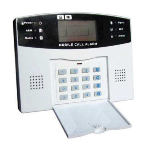
The MINI-DAP II control panel is designed for Data Aire Ceiling systems with one or two cooling stages, one heating
stage and a humidifier. This microprocessor based control offers innovative features and “state of the art” technology.
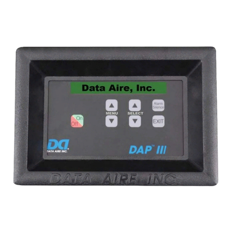
Figure 1: Mini-Dap II Panel
Design Features
• Microprocessor based dual layer board
design
• 16 characters liquid crystal display (LCD)
• Panel mounted temperature and humidity
sensor are standard
• Nonvolatile memory storage for all
programmed settings and alarm history (5
latest alarms)
• Printed circuit board mounted audio alarm
• Five control outputs for fan, cooling stage 1,
cooling stage 2, heat, humidifier
• Five alarm inputs with three selectable
messages
• Optional plug-in remote alarm contact
Software Features
• Setpoint deviation control logic
• Selectable night setback and on/off
functions provide an economical control
solution
• Adjustable system reaction time (Adjustment
rate)
• All settings are programmed using menu
driven soft-touch keys
• Adjustable temperature and humidity
deadband
• °C to °F conversion
• Two level passwords for menus access
• Calibration offset for temperature and
humidity sensor
• Manual diagnostics for components
troubleshooting
REV 8/03 4

REV 8/03 5
Protective & Safety features
• Metal shell enclosure protects panel from
electromagnetic interference, environmental
contamination and handling damage.
• Protected 24 VAC power input:
- 1amp fuse for processor portion of the
PC board
- 5 amp fuse for relay outputs
- Metal Oxide Varistor (MOV) snubs the
transient voltage and protect the circuit
board from an excessive power.
• Opto-isolators for 24 VAC signal inputs
protect the processor from electrical noise of
contactors, compressors and motors, ect.
Conditions and Functions Displayed
• Current room temperature (°F or °C)
• Current room humidity (% RH)
• Cooling stage (1st stage , 2nd stage)
• Reheat
• Humidification or Dehumidification
• Date and Time
• Occupied or Unoccupied period *
* Only displayed when night setback feature is enabled.
Alarms Displayed
• High Temperature Warning
• Low Temperature Warning
• High Humidity Warning
• Low Humidity Warning
• High Condensate Water
• No Air Flow
• Firestat
• Compressor Short-cycle Warning
• Temperature Sensor Fail
• Humidity Sensor Fail
• Power Failure *
• Change Filter *
• Humidifier Fail *
• No Water Flow *
• Fan Overload *
• Local Alarm 1*
• Local Alarm 2*
• Smoke Alarm *
• High Pressure Compressor 1 **
• High Pressure Compressor 2 **
• Low Pressure 1*
• Low AC Voltage Warning
* Alarm displays require additional components or sensors and programmable selections. Some
alarm messages are selected using one of three optional alarm menus.
** These alarms will be set-up at the factory as defaults on single or dual compressor unit.
Historical Data
• Maximum and minimum temperature and humidity since unit has been on.
• Last five alarms to occur.
Location Considerations
Locate the MINI-DAP II panel as follows:
• On a partitioning interior wall, and approximately 5ft (1.5 m) above the floor in a location of the best
average room temperature, room humidity and good air movement.
• Away from direct sunlight or radiant heat, outside walls or behind doors, air discharge grilles or
outside doors.
• Away from steam or water pipes, warm air stacks, unheated/uncooled areas, monitors or sources of
electrical interference.
CAUTION: Shock Hazard. Disconnect power before wiring connections are made
to prevent electrical shock or possible damage to the equipment.

Figure 2: Terminal identification and circuit board details.
Installation and Wiring
To install and wire the MINI-DAP II panel:
1. Use a Phillips screwdriver to loosen the side screws of the panel.
2. Remove the cover of the MINI-DAP II panel. Place the panel against the wall, mark the location of
three mounting holes. See figure 3.
3. Use plastic anchors and screws for mounting on drywall or plaster (recommended).
4. Connect one end of the factory provided cable to the unit terminal strip, refer to unit wiring diagram for
details. Use the color coded wires to designate the functions and terminal number. See figure 2.
5. Use color code to identify the wire function and connect the other end of the cable to MINI-DAP II
panel.
CAUTION: Equipment Damage Hazard. Before applying power, make all wiring connections and
check the connections. Short circuited or improperly connected wires may result in permanent damage to
the unit.
Figure 3: Wall mounting hole location
REV 8/03 6

REV 8/03 7
Installing the Optional Remote Alarm Contact
1. Turn the Mini-Dap II off. Loosen the side screws and remove the panel cover.
2. Remove four screws that secure the 2nd layer board to the base board. See figure 4.
3. Unplug the 2nd layer board.
4. Plug the summary alarm contact board to CON4 plug on the base board. See figure 4.
5. Reinstall the 2nd layer board back to the base board.
Panel Operation
Button Functions
Menu: Press Menu button to go to desired menu.
Select: Press Select button to display current setting, to change setting or to exit menu mode.
Alarm Silence: Press Select button to silence an audio alarm.
Note: The last value to appear is stored for use. Go to Exit menu, press Select button twice to
Return to the normal operation.
Menu Designation
* Apply for night setback option only. These menus will only show when menu #13 is set to “Y”.
1. SETPOINTS
2. OVERRIDE RQST*
3. PASSWORD A
4. TEMP SETPOINT
5. HUMID SETPOINT
6. COMP LEAD/LAG
7. ADJUST RATE
8. SET TIME
9. CALIB CLOCK
10. TEMP/HUM HIST
11. ALARM HISTORY
12. PASSWORD B
13. DAY SCHEDULE
14. OVERRIDE ENBL*
15. OVERRIDE TIME*
16. SETUP COOL*
17. SETBACK HEAT*
18. SETUP DEHUM*
19. SETBACK HUMID*
20. MON SCHEDULE *
21. TUE SCHEDULE*
22. WED SCHEDULE*
23. THU SCHEDULE*
24. FRI SCHEDULE*
25. SAT SCHEDULE*
26. SUN SCHEDULE*
27. TEMP SCALE
28. TEMP DEADBAND
29. HI TEMP LIMIT
30. LO TEMP LIMIT
31. CALIB TEMP
32. HUM DEADBAND
33. HI HUM LIMIT
34. LO HUM LIMIT
35. CALIB HUMID
36. AUDIO ALARM
37. RESTART MODE
38. START DELAY
39. FIRE STAT
40. OPT ALARM 1
41. OPT ALARM 2
42. OPT ALARM 3
43. FAN MODE
44. COOLING EQUIP
45. HEATING EQUIP
46. HUMIDIFIER
47. DEHUMIDIFIER
48. PASSWORD A
49. PASSWORD B

Figure 4: Board assembly with
temperature, humidity sensor and optional summary alarm contact
Programming and Selections
Menu Operations and Settings
To access the menus setting of Mini-Dap II,
Press Menu button to go to menu 1
1-SET POINTS
Press Select button to display current
temperature setpoint report
TEMP SP: 72°F
Press Select button again to display current
humidity setpoint report
HUM SP: 50%
Press Menu button
NOTE: Menu #2 -OVERRIDE RQST will not
show if Menu #13- DAY SCHEDULE is set for
“N” or Menu #14-OVERRIDE ENBL is set for “N”
2-OVERRIDE RQST
Press Select button to display current setting
OVERRIDE RQST: N (No)
Press Select button to change to “Y” (yes)
An override request will temporarily
force the Mini-DAP II to operate in
“occupied” mode for the time period
REV 8/03 8

REV 8/03 9
specified on Menu 15-OVERRIDE TIME
and display will show : “OVERRIDE
ACTIVE”. Remember Menu 14-
OVERRIDE ENBL must be set to “Y” to
allow override requests, otherwise this
menu will never appear.
Press Menu button
EXIT THE MENU - Press Select button twice
to exit to the normal operating
Otherwise press Menu button to advance to the
next menu
3-PASSWORD A
Press Select button to enter password.
PASSWORD A: OO
Default password is 00
Press Select button to scroll the password from
00 to 99. After entering the password, press
Menu button to advance to menu 4. If an
incorrect password is entered, panel will display
“ BAD PASSWORD” for one minute and
automatically exit.
PROCEDURE TO RETRIEVE PASSWORDS
ON MINI-DAP II PANEL
To retrieve the passwords on Mini-DAP II, turn
the panel off. Press and hold the menu and
select button down simultaneously while turning
the panel back on. Release buttons after panel
comes on. The panel will go thru the self-test
then display the password A and B. Reset the
panel (turn it off then back on) in order to go
back to normal running mode. The passwords
should be recorded for future reference.
Otherwise panel will advance to menu 4
4- TEMP SETPOINT
Press Select button to change the temperature
setpoint. The temperature setpoint will cycle
from 65°F to 85°F. Default value is 72°F
Press Menu button to advance to the next menu
5- HUMID SETPOINT
Press Select button to change the humidity
setpoint. The humidity setpoint will cycle from
30% to 70%. Default value is 50%
Press Menu button to advance to the next menu
6- COMP LEAD/LAG
Press Select button to change the setting from 1
LEAD to 2 LEAD or to AUTO. Default setting is
1 LEAD.
1 LEAD: Compressor #1 will be the lead
compressor.
2 LEAD: Compressor #2 will be the lead
compressor (if used)
AUTO: Compressors lead/lag sequence
will change every 168 Hrs of operation.
7- ADJUSTMENT RATE
Press Select button to change the setting from 1
to 5 minutes. This is the interstage time delay /
system reaction time. Default setting is 1 minute.
This can be used to avoid a short cycle in the
system.
Press Menu button to advance to the next menu
8- SET TIME
Press Select button to show the Minute
SET MINUTE: 00:00
Press Select button to change minute, press
Menu to go to Hour setting
SET HOUR: 00:00
Press Select button to change hour, press Menu
to go to Year setting
SET YEAR: 1997
Press Select button to change year, press Menu
to go to Month setting
SET MONTH: JAN
Press Select button to change month, press
Menu to go to Date setting
SET MONTH: JAN 1
Press Select button to change month then press
Menu to go to the next menu
9- CALIB CLOCK
Press Select button for the report of the current
setting. Calib clock is designed to compensate
for the inherent inaccuracy of the micro-
processor crystal used as the time base for the
real time clock in the Mini-Dap II. When panel is
first powered up the clock error is set equal to 0.
In most cases this will result in a real time error
of 30 seconds to couple minutes per day. This
Calib clock menu allows the user to set the
observed error so that this error amount of time
is compensated for each 24 hours period.
Press Menu button to advance to the next menu
10- TEMP/ HUM HISTORY
Press Select button for the report of the present,
minimum and the maximum temperature since
the last power on. Press Select button again for
the report of the humidity.
Press Menu button to advance to the next menu
11- ALARM HISTORY
Press Select button for the report of the last 5
alarms in order of most recent occurrence. 1 =
most recent, 5 = oldest.
Press Select button to cycle through the alarm
history list
Press Menu button

REV 8/03 10
EXIT THE MENU - Press Select
button twice to exit to the normal operation
Otherwise press Menu button to advance to the
next menu
12-PASSWORD B
Press Select button to enter password.
PASSWORD B: OO
Default password is 00
Press Select button to cycle the password from
00 to 99. After entering the password, press
Menu button to advance to menu 13. if an
incorrect password is entered, panel will display
“ BAD PASSWORD” for one minute and
automatically exit. See the Procedure To
Retrieve Password On MINI-DAP II above.
Otherwise panel will advance to the next menu
Press Menu button to advance to the next menu
13-DAY SCHEDULE
Press Select button to display the current setting
DAY SCHEDULE: Y
Y (Yes) or N (No)
Press Select button to change the setting to NO
The time-of-day schedule can be turned
on and off at this menu. When this
menu is set to Y (YES), the Mini-DAP
operates according to the time-of-day
schedule specified in Menus 20 through
26. If this menu is set to N (NO), the
Mini-DAP does not follow a schedule. It
operates continuously in the normal
mode.
NOTE: All the day schedule menus ( 14
to 26) below will not show if Menu #13 is
set for “N”.
Press Menu button to advance to the next menu
14-OVERRIDE ENBL.
Press Select button to display the current setting
OVERRIDE ENBL: Y
Y (Yes) or N (No)
Press Select button to change the setting to NO
This menu enables and disables user
requests to override the time-of-day
schedule and force the Mini-DAP into
“occupied” mode. If this menu is set to
Y (YES), the “Menu 2-OVERRIDE
RQST” appears to allow override
requests. If this menu is set to N (NO),
then “Menu 2 OVERRIDE RQST” never
appears and override requests are
inoperable.
Press Menu button to advance to the next menu
15-OVERRIDE TIME
Press Select button to display the current setting
OVERRIDE HRS: 1
1 to 12 hours
Press Select button to change the Hour
This menu specifies the duration of each
override request made using “Menu 2-
OVERRIDE RQST”.
Press Menu button to advance to the next menu
16-SETUP COOL
Press Select button to display the current setting
SETUP COOL: 5 0 to 30°F
Press Select button to change the temperature
range from 1°F to 30°F. Default value is 5°F
When a SETBACK/UP time-of-day
schedule is in effect and the Mini-DAP is
operating in the “unoccupied” mode, the
effective cooling setpoint will be
adjusted upward by the amount
specified in this menu.
Press Menu button to advance to the next menu
17-SETBACK HEAT
Press Select button to display the current setting
SETBACK HEAT: 5 0 to 30° F
Press Select button to change the temperature
range from 1°F to 30°F. Default value is 5°F
When a SETBACK/UP time-of-day
schedule is in effect and the Mini-DAP is
operating in the “unoccupied” mode, the
effective heating setpoint will be
adjusted downward by the amount
specified in this menu.
Press Menu button to advance to the next menu
18-SETUP DEHUM
Press Select button to display the current setting
SETUP DEHUM: 5 0 to 30% RH
Press Select button to change the humidity
range from 1 % to 30 %. Default value is 5 %
When a SETBACK/UP time-of-day
schedule is in effect and the Mini-DAP II
is operating in the “unoccupied” mode,
the effective setpoint for
dehumidification will be adjusted upward
by the amount specified in the menu.
Press Menu button to advance to the next menu
19-SETBACK HUMID
Press Select button to display the current setting
SETBACK HUMID: 5 0 to 30% RH
Press Select button to change the humidity
range from 1 % to 30 %. Default value is 5 %
When a SETBACK/UP time-of-day
schedule is in effect and the Mini-DAP is
operating in the “unoccupied” mode, the
effective setpoint for humidification will
be adjusted downward by the amount
specified in the menu.

REV 8/03 11
Press Menu button to advance to the next menu
20- MON. SCHEDULE
Press Select button to display the current setting
MON: SETBACK/UP
SETBACK/UP or ON/OFF
Press Select button to change the setting from
setback/up to on/off. Default setting is
setback/up.
Press Menu button to go to the next setting. Use
Select button to set the start time for occupied
period. Default value is “N/C” (no change), this
means the unit will run in occupied mode all the
time. The time is set with 15 minutes increment.
OCCUPIED: XX:XX N/C
(NO CHANGE): 00:00 TO 23:45
Press Menu button to go to the next setting. Use
Select button to set the start time for unoccupied
period. Default value is “N/C” (no change), this
means the unit will run in occupied mode all the
time. The time is set with 15 minutes increment
UNOCCUPIED: XX:XX N/C
(NO CHANGE): 00:00 TO 23:45
All the day schedules in menus 20
through 26 are set in the same manner.
The Mini-DAP operates normally during
all periods designated as occupied.
During unoccupied periods, the Mini-
DAP operates in one of two ways,
depending on which type of schedule is
selected:
SETUP/SETBACK OPERATION
During unoccupied periods of a
SETBACK-UP schedule, the Mini-DAP II
will operate normally, except that it will
adjust its temperature and humidity
setpoint according to the values set in
menus 16 through 19. Operation of the
fan is TO BE SPECIFIED on menu #43.
ON/OFF OPERATION
During unoccupied periods of an
ON/OFF schedule, the Mini-DAP will
deactivate all heating, cooling,
humidification and dehumidification, and
the fan will remain off.
Press Menu button to advance to the next menu
21-TUE SCHEDULE
Similar in all respects to MON SCHEDULE.
Press Menu button to advance to the next menu
22-WED SCHEDULE
Similar in all respects to MON SCHEDULE.
Press Menu button to advance to the next menu
23-THU SCHEDULE
Similar in all respects to MON SCHEDULE.
Press Menu button to advance to the next menu
24-FRI SCHEDULE
Similar in all respects to MON SCHEDULE.
Press Menu button to advance to the next menu
25-SAT SCHEDULE
Similar in all respects to MON SCHEDULE.
Press Menu button to advance to the next menu
26-SUN SCHEDULE
Similar in all respects to MON SCHEDULE.
Press Menu button to advance to the next menu
EXIT THE MENU
Press Select button twice to exit to normal
operation. Otherwise press Menu button to go to
the next menu
27- TEMP SCALE
Press Select button to choose either F or C
temperature scale. Default setting is F scale
Press Menu button to advance to the next menu
28- TEMP DEADBAND
Press Select button to change the setting from
1°F to 5°F. default setting is 2°F.
Press Menu button to advance to the next menu
29- HI TEMP LIMIT
Press Select button to cycle the setting of the
high temperature alarm limit from 50°F to 90°F
in 1°F increments or Hi Temp Lim Disab.
Default setting is 80°F.
Press Menu button to advance to the next menu
30- LO TEMP LIMIT
Press Select button to cycle the setting of the
low temperature alarm limit from 50°F to 90°F in
1°F increments or Lo Temp Lim Disab.
Default setting is 60°F.
Press Menu button to advance to the next menu
31- CALIB TEMP
Press Select button to display the current
temperature with default 0 calibration offset.
TEMP+ 0.0 = xx
Press Select button to change the temperature
offset to make temperature reading matches a
reference temperature reading. The offset value
cycles from –20 to +20, default value is 0.0
Press Menu button to advance to the next menu
32- HUM DEADBAND
Press Select button to change the setting from
1% to 10%. Default setting is 3%
Press Menu button to advance to the next menu
33- HI HUM LIM
Press Select button to cycle the setting of the
high humidity alarm limit from 10% to 90% in 1%
increments or Hi Hum Lim Disab. Default setting
is 60%

REV 8/03 12
Press Menu button to advance to the next menu
34- LO HUM LIM
Press Select button to cycle the setting of the
low humidity alarm limit from 10% to 90% in 1%
increments or Lo Hum lim Disab. Default setting
is 40%
Press Menu button to advance to the next menu
35- CALIB HUMID
Press Select button to display the current
humidity with default 0 calibration offset.
HUM + 0.0 = xx
Press Select button to change the humidity
offset until the humidity reading matches a
reference humidity reading.
Press Menu button to advance to the next menu
36- AUDIO ALARM
Press Select button to display the current audio
alarm mode and for a sample of the sound level.
Default value is long beep
TONE: LONG BEEP
Press Select button to cycle the audio alarm to
the desired mode of silent, full on, short beep,
double or long beep
Press Menu button to advance to the next menu
37- RESTART MODE
Press Select button to display the current power
failure restart mode. Default setting is auto
RESTART: AUTO
Press Select button to cycle to the desired
restart mode:
• Auto: unit will automatically
restart after a power failure with
no message or audio alarm Press Menu button to advance to the next menu
• Auto M: unit will restart with
alarm message only. Press
Select button to acknowledge the
message
• Auto A : unit will restart with
alarm message and audio alarm.
Press Select button to
acknowledge the alarm
• Manual: unit will not restart until
the power failure alarm is
acknowledged. Press Select
button to acknowledge the alarm
and restart unit
Press Menu button to advance to the next menu
38 – START DELAY
Press Select button to view the current setting
DELAY: 00:05
Press Select button to cycle to the desired start
time delay. Minimum value is 5 seconds,
maximum value is 5 minutes. Default value is 5
seconds
Press Menu button to advance to the next menu
39 – FIRE STAT
Press Select button to view the current setting
FIRE STAT: 100 F
Press Select button to cycle to the desired
firestat trip point based on the return air
temperature sensor. Minimum value is 100°F,
maximum value is 200°F. Default value is 100°F
Press Menu button to advance to the next menu
40 – OPT ALARM 1
Press Select button to view the current setting
alarm message for alarm input , press Select
button to cycle to the desired alarm message for
this alarm input. The default setting for a DX unit
is Hi Press C1 (high-pressure compressor #1),
otherwise it is Local Alarm 1 or one listed
below:
• Smoke Alarm – this will shutdown unit
when it is detected.
• No Water Flow
Press Menu button to advance to the next menu
41 – OPT ALARM 2
Press Select button to view the current setting
alarm message for alarm input , press Select
button to cycle to the desired alarm message for
this alarm input. The default setting Local Alarm
2. Other alarm selections are:
• Smoke Alarm – this will shutdown unit
when it is detected.
• Change Filter
• Hi Press C2 (for 2 compressors unit only)
• Lo Press C1
42 – OPT ALARM 3
Press Select button to view the current setting
alarm message for alarm input , press Select
button to cycle to the desired alarm message for
this alarm input. The default setting is Humid
Fail. This alarm will shut down the humidifier.
Other selections are:
• Smoke Alarm – this will shutdown unit
when it is detected.
• No Water Flow
• Change Filter
• Fan Overload
Press Menu button to advance to the next menu
43- FAN MODE
Press Select button to view the current setting
FAN MODE: AUTO
Press Select button to change to cont. Default
setting is Auto.
• AUTO: fan comes on when unit calls for
cooling, heating, dehumidification and

REV 8/03 13
humidification. It goes off in one minute
when no functions are required.
• CONT: fan runs continuously during the
occupied mode or normal mode even when
no functions are needed.
Press Menu button
EXIT THE MENU
Press Select button twice to exit to normal
operation. Otherwise press Menu button to
advance to the next menu
44– COOLING EQUIP
Press Select button to view the current setting
COOL: PRI
This is the default setting, press select button to
change to:
PRI/PRI (For 2 compressors system)
VALVE (For chilled water unit).
PRI/SEC (For 1 compressor w/ unloader)
Press Menu button to advance to the next menu
45 – HEATING EQUIP
Press Select button to view the current setting
HEAT STAGE: YES
Press Select button to cycle from Yes to No
Press Menu button to advance to the next menu
46 – HUMDIFIER
Press Select button to view the current setting
HUMID: COMPUTER
Press Select button to cycle from Computer to
Comfort or to None.
• Computer : reheat will be locked out when
humidifier is called for.
• Comfort : this will allow reheat and
humidifier to work simultaneously.
• None : this will disable the humidifier
Press Menu button to advance to the next menu
47 – DEHUMIDIFIER
Press Select button to view the current setting
DEHUMID: YES W/ INH (Yes with inhibit)
Or YES WO/INH (Yes without inhibit).
See Occupied Dehumidification Logic on
page 15 for detail logic.
Press Select button to cycle from Yes to No
Press Menu button
EXIT THE MENU
Press Select button twice to exit to normal
operation
Press Menu button to advance to the next menu
48-PASSWORD A
Press Select button to display the current
password.
PASSWORD A: OO
Default password is 00
Press Select button to change the password
from 00 to 99.
Press Menu button to advance to the next menu
49-PASSWORD B
Press Select button to display the current
password.
PASSWORD B: OO
Default password is 00
Press Select button to change the password
from 00 to 99.
Press Menu button
EXIT THE MENU
Press Select button twice to exit to normal
operation or press Menu button to cycle back to
menu 1.
Manual Diagnostic Program
To enter Manual diagnostic program, simply
turn the control panel off. Press and hold the
menu and select button down simultaneously
while turning the panel back on. Release buttons
after the panel comes on. The panel will go thru
the self-test then enter to the first diagnostic test:
1- MENU & SELECT
MENU: - SELECT: -
Test #1 is the button test, this test will
automatically start after the above title is
shown. Each time either the menu or the
select button is pressed the dash (-) will
change to asterisk (*) for as long as the
button is held down.
Press both Menu and Select button at the same
time, the display will switch to test #2.
2- TEST RELAYS
Press Select button to manually cycle on one
relay at a time with the function name, PCB
relay location and the pin connector number. For
example: BLOWER K1 P1-4. This indicates
blower relay is K1 on the PC board and the
24vac output for blower is on pin #4 of the panel.
Press the menu button to go to the next test.
3- AUDIO ALARM
Press Select button to manually turn on the
audio alarm. The display will show AUDIO
ALARM: ON and the audio alarm will sound.
Press Select button to cycle the audio alarm
from on to off.
Press the menu button to go to the next test.

REV 8/03 14
4- TMP,HUM,AD CAL
Press select button to display the temperature
sensor raw value and its calibration offse,t which
is programmed on menu #31. Press select
button to display the humidity sensor raw value
and its calibration offset, which is programmed
on menu #35. Press select button again, panel
will display the reference voltage of the sensors
(temperature and humidity): REF: 5.000 (VDC).
Press select button to display the voltage
reading (raw value) across sensors.
Note: the offset is the amount of calibration
required for a true reading of room condition.
Press the menu button to go to the next test.
5- ALARM INPUT
Press select button to display the 24 VAC alarm
inputs on the terminal strip of the panel: P 09,
10, 11,12,13. The connector terminal number
indicates the alarm input is on, a dash mark (--)
means the alarm input is off. The alarm inputs
(terminal numbers) are as follows:
9. High condensate alarm
10. No air flow alarm
11. Optional input #1 (may be set for Hi
press C1 for single compressor)
12. Optional input #2 (may be set for Hi
press C2 for dual compressor)
13. Optional input #3
Press menu button to go back to test 1.
To go back to the normal operation, Turn panel
off, wait 5 seconds then turn the panel back on.
Panel will go thru the self-test then unit will come
back on.
Control Logic
This control panel can be programmed in two different types of operation:
1. Continuous operation, no setback or schedule. This operation is normally applied to a
computer room or equipment room. This requires the menu #13 on the MINI-DAP II panel
set to “N”. the operational logic of this mode is the same as the logic of the OCCUPIED
mode. See below logic for details.
2. Setback/up or On/Off operation. This requires that menu #13 is set to “Y” and the seven
days schedules are set on menu #20 thru #26. See Menus setting for details. This operation has two
periods: OCCUPIED period and UNOCCUPIED period. See below logic for details.
Important note:
1. If menu #13- DAY SCHEDULE is set for “Y”, the time-of-day schedule setting for occupied and
unoccupied period must be set on menu #20 to #26. If they are left at “N/C”, the control panel will
operate as it is in the occupied period at all time.
2. Mini-DAP II panel does not have a real time clock with backup battery therefore the date and time
must be reset every time the panel loses power, otherwise the panel will stay in the same mode as
last time it is turned off and “TIME NOT SET” message will appear.
Occupied or Normal mode
When unit is in the “OCCUPIED” mode or normal operation, the MINI-DAP II will operate in the
following control logic:
EVAPORATOR FAN
The blower will operate based on the setting of menu #43-FAN MODE: AUTO OR CONT
AUTO: fan comes on when unit calls for cooling, heating, dehumidification and
humidification. It goes off in one minute when no functions are called for.
CONT: fan runs continuously during the occupied mode even when no functions are needed.
OCCUPIED COOLING LOGIC
1. 5 minutes delay between start to start of the compressor (anti short cycle delay).
2. 2 minutes delay between stop to start of the same compressor.
3. Compressor sequences as follows:
COOL 1 ON AT TEMPERATURE SETPOINT + TEMPERATURE DEADBAND
COOL 2 ON AT TEMPERATURE SETPOINT + TEMPERATURE DEADBAND + .3°F (IF EXISTS)

REV 8/03 15
COOL 2 OFF AT TEMPERATURE SETPOINT + TEMPERATURE DEADBAND
COOL 1 OFF AT TEMPERATURE SETPOINT
OCCUPIED HEATING LOGIC
1. 1 minute delay between stop to start of the reheat. Reheat will be overrided by humidification in the
computer room.
2. Heating sequences as follows:
HEAT ON AT TEMPERATURE SETPOINT – TEMPERATURE DEADBAND -.3 °FHEAT OFF AT
TEMPERATURE SETPOINT- TEMPERATURE DEADBAND
OCCUPIED HUMIDIFICATION LOGIC
1. Heat will be overrided by humidification unless menu #46 is set for “COMFORT”.
2. 1 minute delay between stop to start of humidification.
3. 5 minutes delay between humidification and dehumidification.
4. Humidification sequences as follows:
HUMIDIFICATION ON AT HUMIDITY SETPOINT + HUMIDITY DEADBAND
HUMIDIFICATION OFF AT HUMIDITY SETPOINT –1%
OCCUPIED DEHUMIDIFICATION LOGIC
1. Dehumidification is not governed by the adjustment rate but the operation will not violate compressor
short cycle times
2. Heating is used to reheat the overcooled and dehumified air but heating short cycle times will not be
violated. Also, if heating comes on and return air temperature is still below temperature setpoint
minus temperature deadband minus 2°F, with (Menu 47) the Dehumidifier set to “Yes W/INH” the
dehumidification cooling will be inhibited until the temperature goes back to the temperature setpoint.
If Menu 47 is set to “Yes WO/INH”, the dehumidification cooling will allow to stay on until Humidity
setpoint is satisfied regardless the Temperature setpoint.
3. When reheat comes on, the second stage of cooling will go off if it exists.
4. 1 minute delay between stop to start of the dehumidification.
5. Dehumidification compressor staging sequence:
COOL 1 ON AT HUMIDITY SETPOINT + HUMIDITY DEADBAND
COOL 2 ON AT HUMIDITY SETPOINT + HUMIDITY DEADBAND + 1% (IF EXISTS)
COOL 2 OFF AT HUMIDITY SETPOINT + HUMIDITY DEADBAND (IF EXISTS)
COOL 1 OFF AT HUMIDITY SETPOINT
Setback/up mode
When control panel in the unoccupied schedule, unit will operate as following:
EVAPORATOR FAN
The blower will operate based on the setting of menu #43-FAN MODE: AUTO OR CONT
AUTO: fan comes on when unit calls for cooling, heating, dehumidification and
humidification. It goes off in one minute when no functions are called for.
CONT: fan runs continuously during the occupied mode even when no functions are needed
SETUP COOLING LOGIC
When a SETBACK/UP time-of-day schedule is in effect and the Mini-Dap II is operating in the
“Unoccupied” mode, the effective heating setpoint will be adjusted upward by the amount specified
in menu #16.

REV 8/03 16
1. 5 minutes delay between start to start of the compressor ( anti short cycle delay).
2. 2 minutes delay between stop to start of the same compressor.
3. Compressor sequences as follows:
COOL1 ON AT TEMP SETPOINT + COOL SETBACK TEMP + TEMP DEADBANB
COOL2 ON AT TEMP SETPOINT + COOL SETBACK TEMP + TEMP DEADBANB + .3°F (IF EXISTS)
COOL2 OFF AT TEMP SETPOINT + COOL SETBACK TEMP + TEMP DEADBAND (IF EXISTS)
COOL1 OFF AT TEMP SETPOINT + COOL SETBACK TEMP
SETBACK HEATING LOGIC
When a SETBACK/UP time-of-day schedule is in effect and the Mini-DAP is operating in the
“unoccupied” mode, the effective heating setpoint will be adjusted downward by the amount
specified in menu #17.
1. 1 minute delay between stop to start of the reheat. Reheat will be overrided by humidification.
2. Heating sequences as follows:
HEAT ON AT TEMP SETPOINT - HEAT SETBACK TEMP – TEMP DEADBAND - .3°F
HEAT OFF AT TEMP SETPOINT – HEAT SETBACK TEMP
SETBACK HUMIDIFICATION LOGIC
When a SETBACK/UP time-of-day schedule is in effect and the Mini-DAP is operating in the
“unoccupied” mode, the effective setpoint for humidification will be adjusted downward by the
amount specified in menu #19.
1. Heat will be overrided by humidification unless menu #46 is set for “COMFORT”.
2. 1 minute delay between stop to start of humidification.
3. 5 minutes delay between humidification and dehumidification.
4. Humidification sequences as follows:
HUMIDIFIER ON AT HUMIDITY SETPOINT – HUMIDITY SETBACK – HUMIDITY DEADBAND
HUMIDIFIER OFF AT HUMIDITY SETPOINT – HUMIDITY SETBACK – 1%
SETUP DEHUMIDIFICATION LOGIC
When a SETBACK/UP time-of-day schedule is in effect and the Mini-DAP is operating in the
“unoccupied” mode, the effective setpoint for dehumidification will be adjusted upward by the
amount specified in menu #18.
1. Dehumidification is not governed by the adjustment rate but the operation will not violate compressor
short cycle times
2. Heating is used to reheat the overcooled and dehumified air but heating short cycle times will not be
violated. Also if heating comes on and return air temperature is still below temperature setpoint minus
temperature deadband minus 2°F, the dehumidification cooling will be inhibited until the temperature
goes back to the temperature setpoint.
3. When reheat comes on, the second stage of cooling will go off if it exists.
4. 1 minute delay between stop to start of the dehumidification.
5. Dehumidification compressor staging sequence:
COOL1 ON AT HUMIDITY SETPOINT + HUMIDITY SETBACK + HUMIDITY DEADBAND
COOL2 ON AT HUMIDITY SETPOINT + HUMIDITY SETBACK + HUMIDITY DEADBAND + 1%
COOL2 OFF AT HUMIDITY SETPOINT + HUMIDITY SETBACK + 1%
COOL1 OFF AT HUMIDITY SETPOINT + HUMIDITY SETBACK

REV 8/03 17
On/Off mode
If the time-of-day schedule setting for occupied and unoccupied period on menu #20 to #26 are set for
“N/C” or when menu #13- DAY SCHEDULE is set for “N”, the control panel will operate in the “occupied “
mode all the time otherwise it will only operate in the “Occupied “ mode when time-of-day occupied
schedule is in effect.
OCCUPIED SCHEDULE OF ON/OFF MODE
When unit is in the “OCCUPIED” period, the MINI-DAP II will operate in the same control logic as the
“OCCUPIED” period of the SETBACK/UP mode indicated above.
UNOCCUPIED SCHEDULE OF ON/OFF MODE
During the “UNOCCUPIED” period of an ON/OFF schedule, the Mini-Dap II will deactivate all heating,
cooling, humidification and dehumidification, and the fan will remain off.
Alarms Logic
1. HIGH TEMPERATURE ALARM
This indicates that the return air temperature is warmer than the high temperature limit setting. High
temperature reports on the LCD screen and audio alarm sounds. High temperature alarm limit is set on
menu #29.
2. LOW TEMPERATURE ALARM
This indicates that the return air temperature is colder than the low temperature limit. Low temperature
reports on the LCD screen and audio alarm sounds. Low temperature alarm limit is set on menu #30.
3. HIGH HUMIDITY ALARM
This indicates that the return air humidity is higher than the high humidity limit. High humidity level reports
on the LCD screen and audio alarm sounds. High humidity alarm limit is set on menu #33.
4. LOW HUMIDITY ALARM
This indicates that the return air humidity is lower than the low humidity limit. Low humidity level reports
on the LCD screen and audio alarm sounds. Low humidity alarm limit is set on menu #34.
5. NO AIR FLOW ALARM
This requires an airflow sensor. When no airflow is detected, the cooling, heating, humidification and
dehumidification functions are locked out until the alarm condition is corrected. The audio alarm is
activated and “NO AIRFLOW” message is displayed on the LCD.
6. CHANGE FILTER ALARM (optional)
This requires a differential pressure sensor. When dirty filter is detected, the audio alarm is activated and
“CHANGE FILTER” message is displayed on the LCD until the alarm condition is corrected.
7. HUMID FAILURE (optional)
This requires a supply water pressure switch. When water pressure is not detected, the humidifier is held
off, the audio alarm is activated and “HUMID FAILURE” message is displayed on the LCD until the alarm
condition is corrected.
8. HIGH CONDENSATE (WATER LEVEL)
A float switch is installed in the condensate pan to detect a high condensate water level. When high water
level is detected, the cooling, heating, humidification and dehumidification are locked out until the alarm
condition is corrected, the audio alarm is activated and “HIGH CONDENSATE” message is displayed on
the LCD.

REV 8/03 18
9. FIRESTAT ALARM
When return air temperature exceeds firestat temperature limit setting (menu #39). All blower, cooling,
heating, humidification, and dehumidification functions will be immediately terminated. The audio alarm is
activated and “FIRESTAT ALARM” message is displayed. The alarm will disappear when return air
temperature drops below the firestat limit setting and all functions will resume.
WARNING: firestat alarm can be caused by the temperature sensor failure or incorrect calibration.
10. COMPRESSOR SHORT CYCLE
When the compressor has started 5 times within the past 30 minutes for any reasons (cooling or
dehumidification). A “COMP SHORT CYCLE” message is displayed and the audio alarm is activated. The
short cycle time delay between start to start of the same compressor is automatically increased from 5
minutes to 6 minutes for one hour. The alarm message will remain until one hour has elapsed without 10
compressor starts.
REMEMBER this alarm is only a warning, it will not prevent the compressor from coming on.
11. POWER FAILURE
The power restart mode is selected in menu # 37 “ RESTART MODE”. The following is the sequence of
each mode:
AUTO: the unit will start automatically after a power failure or a reset. No audio or message.
AUTO M: the unit will start automatically after a power failure or a reset with alarm message only.
AUTO M: the unit will start automatically after a power failure or a reset with message and audio.
MANUAL: the unit will not start automatically after a power failure or a reset. An alarm message is
displayed and audio alarm is activated. Press the alarm silence button to manually restart unit.
12. TEMP SENSOR FAIL
Temperature sensor values are out of reasonable range. This may be caused by a bad sensor ( see
sensor troubleshooting) or incorrect wiring. When temp sensor fail alarm goes off, cooling will come on
and stay on until the alarm condition is corrected.
WARNING:A temperature sensor failure will cause the firestat alarm to be inoperative.
13. HUM SENSOR FAIL
Humidity sensor values are out of reasonable range. This may be caused by a bad sensor (See sensor
troubleshooting) or incorrect wiring. When the humidity sensor fail alarm goes off, humidification and
dehumidification will be locked out until the alarm condition is corrected.
14. HIGH PRESSURE 1 ALARM (HI PRES C1)
High-pressure alarm for compressor is set on menu #40, “OPT ALARM 1”. This is default setting on this
menu for a DX unit. This alarm goes off when the high-pressure switch opens. “HIGH PRES C1” message
is displayed and audio alarm is activated. Compressor is off and alarm stays on until the high-pressure
switch is manually reset.
15. HIGH PRESSURE 2 ALARM (HI PRES C2)
Apply for dual compressor systems only. The high pressure 2 alarm is set on menu #41, “OPT ALARM 2”.
This is default setting on this menu for 2 compressors unit. This alarm goes off when the high-pressure
switch opens. “HIGH PRES C2” message is displayed and audio alarm is activated. Compressor is off
and alarm stays on until the high-pressure switch is manually reset.
CAUTION: The unit needs to be checked-out by a qualified technician if it goes off on high pressure
frequently.
16. NO WATER FLOW (optional)
This alarm requires a flow switch that is wired to the alarm optional input and menu #42,“OPT ALARM 3”,
is set for “NO WATER FLOW”. When flow switch is opened, alarm will goes off until the alarm condition is
corrected.
17. SMOKE ALARM (optional)
This alarm requires a smoke detector that is wired to the alarm optional input and menu #41 or #42, “OPT
ALARM 2” or “OPT ALARM 3”, are set for “SMOKE ALARM”. When the smoke detector energizes, a
“SMOKE ALARM” message will display and audio alarm will activate. All the blower, cooling, heating and
humidifier will be locked out until the alarm condition is corrected.
Table of contents
Other Data Aire Security System manuals
