Datcon PQRM5100 11 U I Series User manual

PQRM5100 11 Ux Ix xx xx (PS)
Single Phase power transmitter
Instruction manual

PQRM5100 11 Ux Ix xx xx (PS)
2 20200205-V1
Contents
1. About this document.....................................................4
1.1. Function ................................................................................... 4
1.2. Target group............................................................................. 4
1.3. Symbolism used....................................................................... 4
2. For your safety...............................................................5
2.1. Authorized personnel ............................................................... 5
2.2. Appropriate use........................................................................ 5
2.3. Warning about misuse ............................................................. 5
2.4. General safety instructions....................................................... 5
2.5. CE conformity........................................................................... 5
2.6. Environmental instructions ....................................................... 5
3. Product description.......................................................6
3.1. Delivery configuration............................................................... 6
3.2. Type designation...................................................................... 6
3.3. Operating principle ................................................................... 7
3.4. Indicators.................................................................................. 9
3.5. Storage and transport .............................................................. 9
4. Mounting.......................................................................10
4.1. General instructions ............................................................... 10
4.2. Main dimensions of the instrument ........................................ 10
4.3. Mounting ................................................................................ 11
5. Connecting ...................................................................12
5.1. Preparing the connection ....................................................... 12
5.2. Connecting the measuring inputs to power network (1ph, 2w,
1m) ................................................................................................ 13
5.3. Connecting the measuring inputs to power network trough CT
(1ph, 2w, 1m) ................................................................................ 14
5.4. Connecting the measuring inputs to medium power network.
(1ph, 2w, 1m) ................................................................................ 15
5.5. Connecting the measuring inputs to symmetrical three-phase
power network with neutral conductor. (3 phase, 4 wire, 1
measuring) .................................................................................... 16
5.6. Connecting the measuring inputs to symmetrical three-phase
power network without neutral conductor. (3 phase, 3 wire, 1
measuring) .................................................................................... 17

PQRM5100 11 Ux Ix xx xx (PS)
20200205-V1 3
5.7. Connecting the digital outputs................................................ 18
5.8. Connecting to MODBUS RS485 network............................... 20
5.9. Connecting the analog output to signal processing unit......... 21
5.10. Connecting the power supply............................................... 22
5.11. Connecting to PC via USB ................................................... 23
6. Setting-up .....................................................................24
6.1. First steps............................................................................... 24
6.3. Configuration software, Measuring tab. ................................. 26
6.4. Configuration software, Harmonics tab. ................................. 27
6.5. Configuration software, Phasor tab........................................ 28
6.6. Configuration software, Errors tab ......................................... 29
6.7. Configuration software, Configure tab.................................... 30
6.8. Voltage Transformers (VT) ratio settings ............................... 31
6.9. Current Transformers (CT) ratio settings ............................... 32
6.10. Phase lag of CT settings ...................................................... 33
6.11. Sampling time setting........................................................... 34
6.12. Measure layout setting ........................................................ 35
6.13. Current threshold setting...................................................... 37
6.14. Digital output, Energy pulse output settings......................... 38
6.15. Digital output, Energy sign output settings........................... 40
6.16. Digital output, Limit output settings ...................................... 41
6.17. Digital output, Alarm output settings .................................... 44
6.18. Digital output, Demand control function setting.................... 45
6.19 Digital output, Tariff settings................................................. 47
6.20. Analog output settings.......................................................... 48
6.21. Analog output testing ........................................................... 50
6.22. Communication settings....................................................... 52
6.23. Errors ................................................................................... 66
6.24. Setting errors LED................................................................ 68
6.25. Harmonics setting ................................................................ 69
7. Fault rectification.........................................................70
7.1. Fault finding............................................................................ 70
7.2. Repairing................................................................................ 70
8. Dismounting.................................................................71
8.1. Dismounting procedure .......................................................... 71
8.2. Disposal ................................................................................. 72
9. Appendix.......................................................................73
9.1. Technical specification ........................................................... 73
9.2. Application examples ............................................................. 76

PQRM5100 11 Ux Ix xx xx (PS)
4 20200205-V1
1. About this document
1.1. Function
This operating instructions manual has all the information
you need for quick set-up and safe operation of
PQRM5100 11 Ux Ix xx xx.
Please read this manual before you start setup.
1.2. Target group
This operating instructions manual is directed to trained
personnel. The contents of this manual should be made
available to these personnel and put into practice by them.
1.3. Symbolism used
Information, tip, note
This symbol indicates helpful additional information.
Caution, warning, danger
This symbol informs you of a dangerous situation that could
occur. Ignoring this cautionary note can impair the person
and/or the instrument.
•List
The dot set in front indicates a list with no implied sequence.
→Action
This arrow indicates a single action.
1
Sequence
Numbers set in front indicate successive steps in a
procedure.

PQRM5100 11 Ux Ix xx xx (PS)
20200205-V1 5
2. For your safety
2.1. Authorized personnel
All operations described in this operating instructions
manual must be carried out only by trained and authorized
specialist personnel. For safety and warranty reasons, any
internal work on the instruments must be carried out only by
DATCON personnel.
2.2. Appropriate use
The PQRM5100 11 Ux Ix xx xx is a Single Phase power
transmitter. Detailed information on the application range is
available in chapter 3. Product description.
2.3. Warning about misuse
Inappropriate or incorrect use of the instrument can give rise
to application-specific hazards, or damage to system
components through incorrect mounting or adjustment.
2.4. General safety instructions
The PQRM5100 11 Ux Ix xx xx is a high-tech instrument
requiring the strict observance of standard regulations and
guidelines.
The user must take note of the safety instructions in this
operating instructions manual, the country-specific
installation standards as well as all prevailing safety
regulations and accident prevention rules.
2.5. CE conformity
The PQRM5100 11 Ux Ix xx xx is in conformity with the
provisions of the following standards:
MSZ EN 61010-1 (safety)
MSZ EN 61326-1 (EMC)
2.6. Environmental instructions
Protection of the environment is one of our most important
duties.
Please take note of the instructions written in the following
chapters:
•Chapter 3.5. Storage and transport
•Chapter 9.2. Disposal
PQRM5100 11 Ux Ix xx xx (PS)
6 20200205-V1
3. Product description
3.1. Delivery configuration
Delivered items The scope of delivery encompasses:
•PQRM5100 11 Ux Ix xx xx
•documentation:
this operating instructions
certification
warranty
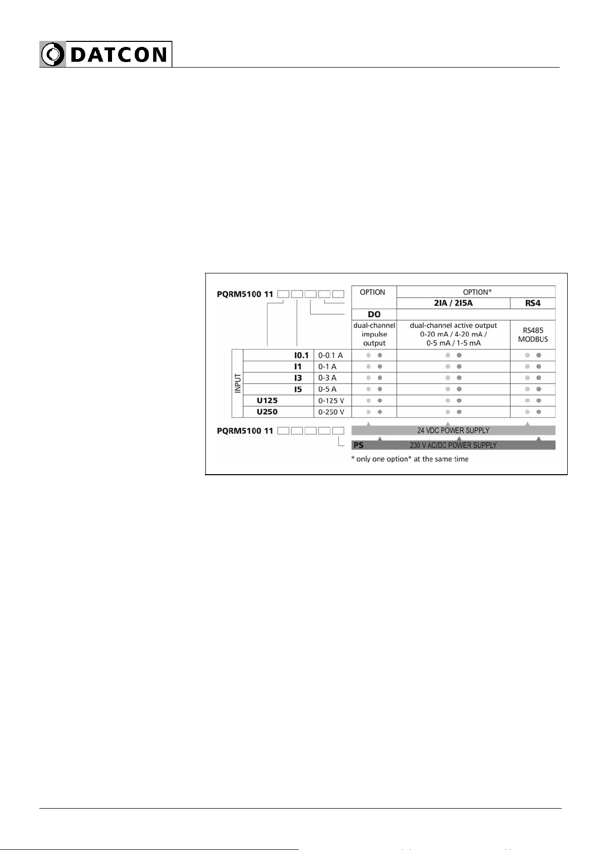
3.2. Type designation

PQRM5100 11 Ux Ix xx xx (PS)
20200205-V1 7
3.3. Operating principle
Area of application
The PQRM5100 11 Ux Ix xx xx (PS) Single Phase power
transmitter measures the characteristic for single-phase
network system.
The current input of the instrument is isolated from the
network with wideband current transformers. The voltage
input of the instrument is galvanic connection in the
network. The PQRM5100 11 Ux Ix xx xx (PS) Single Phase
power transmitter has many measurement configurations.
The measurement configuration and the output parameters
are configurable from PC via USB port with the help of a
free of charge configuration software.
Options:
•Two 4-20 mA / 0-20 mA or 0-5 mA / 1-5 mA galvanic
isolated, configurable, scalable analog output
•RS485 galvanic isolated communication output with
MODBUS RTU slave protocol. 32 instruments can be
connected to the PLC or to the computer.
One option can be installed (dual analog output or
communication output) at the same time.
Operating principle
The voltage divider output and current-transformer output
signals is led through the signal conditioner and protection
circuits to the 16 bit A/D converter inputs. The digitalized
signals are processed by the instruments microcontroller.
The calculated parameters are produced in IEEE754
standard “Single Precision” figure. The calculated energy
values (+EP, -EP, +EQ, -EQ) and the settings are stored an
EEPROM for an unlimited period of time. The switched-
mode power supply of the instrument produces two galvanic
isolated output voltages: one for the instrument circuitry and
one for the installed options.
Power supply The instrument has two power supply version:
PQRM5100 11 Ux Ix xx xx 24 VDC
PQRM5100 11 Ux Ix xx xx PS 230 V AC/DC

PQRM5100 11 Ux Ix xx xx (PS)
8 20200205-V1
Measuring parameters: •Ueff : Measured voltage [V]
•Ieff : Measured current [A]
•P: Measured active power [W]
•Q: Measured reactive power [VAr]
•S: Measured apparent power [VA]
•PF: Calculated power factor
•f: Measured network freuqvency [Hz]
•THDU: Calculated total harmonic distortion of phase
voltage (up to 19. harmonic ) [%]
•THDI: Calculated total harmonic distortion of phase current
(up to 19. harmonic ) [%]
•+EP: Measured values of consument active energy [Wh]
•-EP: Measured values of produced active energy [Wh]
•+Eq: Measured values of inductiv reactive energy [VArh]
•-Eq: Measured values of capacitiv reactive energy [VArh]
PQRM5100 11 Ux Ix xx xx (PS)
20200205-V1 9
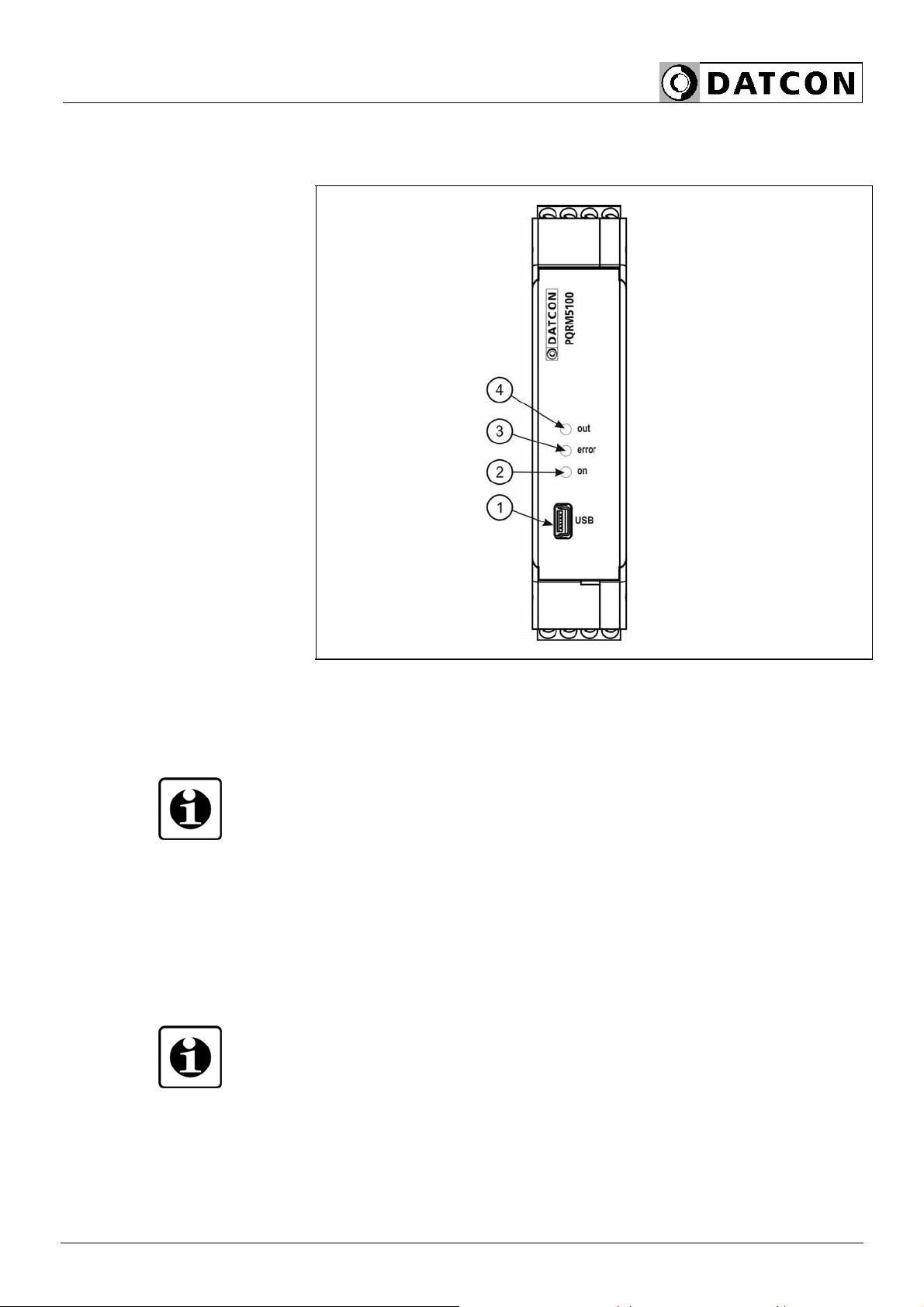
3.4. Indicators
The following figure shows the frontpanel:
1. USB configuration port
2. „on” green indicator for indicating that device is ready.
3. „error” red indicator for indicating that a kind of error
occurred.
4. „out” yellow indicator for indicating the state of the option.
The indicator blinking (2IA option), or light if a successful
data exchange has granted through the communication
output (RS4 option)
3.5. Storage and transport
This instrument should be stored and transport in places
whose climatic conditions are in accordance with chapter
9.1. as described under the title: Environmental conditions.
The packaging of PQRM5100 11 Ux Ix xx xx consist of
environment-friendly, recyclable cardboard is used to
protect the instrument against the impacts of normal
stresses occurring during transportation. The corrugated
cardboard box is made from environment-friendly,
recyclable paper. The inner protective material is nylon,
which should be disposed of via specialized recycling
companies.
PQRM5100 11 Ux Ix xx xx (PS)
10 20200205-V1
4. Mounting
4.1. General instructions
The instrument should be installed in a cabinet with
sufficient IP protection, where the operating conditions are
in accordance with chapter 9.1. , as described under the
title: Operating conditions.
Mounting position
The instruments are designed in housing for mounting on
TS-35 rail.
The instruments should be mounted in vertical position
(horizontal rail position).
Horizontal mounting may cause overheating and damage of
the instrument.
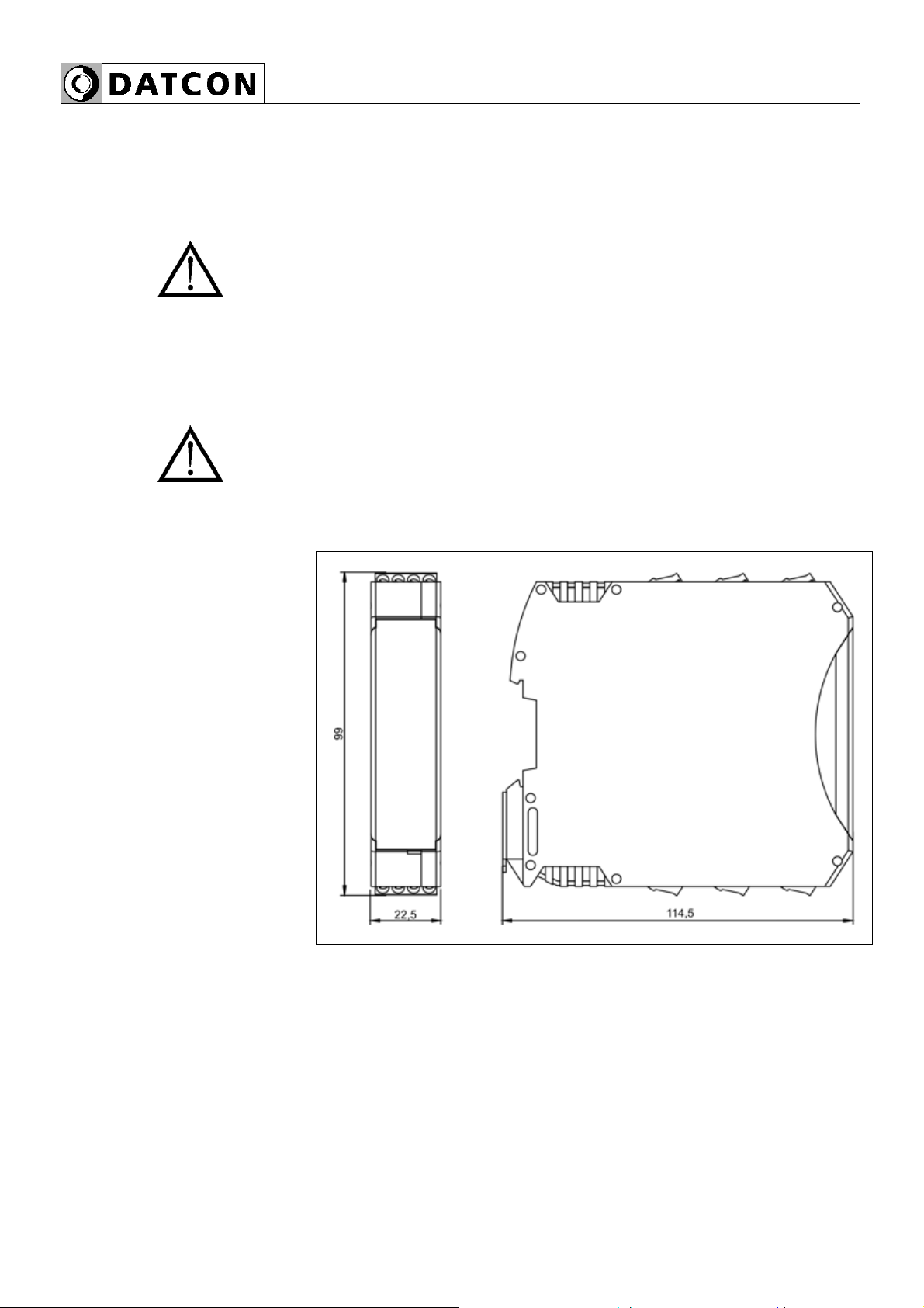
4.2. Main dimensions of the instrument
PQRM5100 11 Ux Ix xx xx (PS)
20200205-V1 11
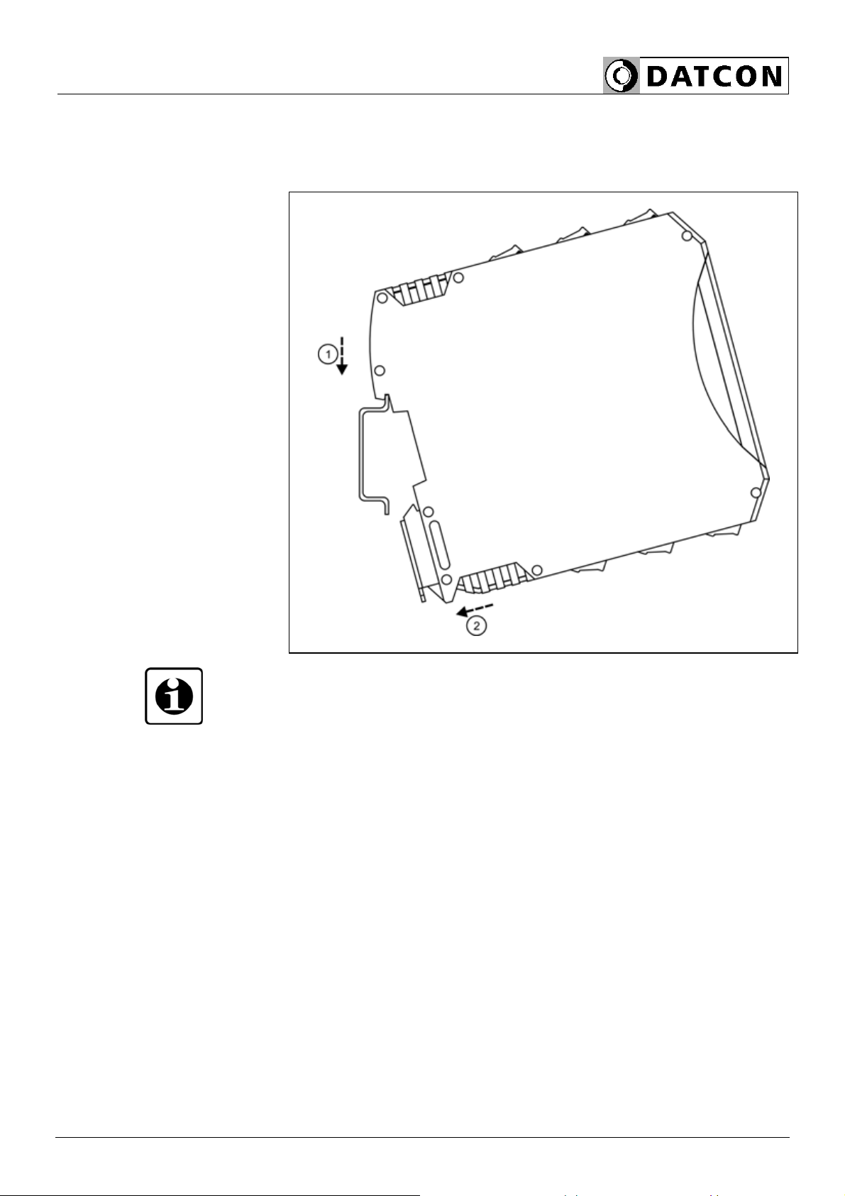
4.3. Mounting
The following figure shows the mounting procedures (fixing
on the rail):
Mounting on the rail
The mounting doesn’t need any tool.
1. Tilt the instrument according to the figure; put the
instrument’s mounting hole onto the upper edge of the rail
(figure step 1.).
2. Push the instrument’s bottom onto the bottom edge of the
rail (figure step 2.); you will hear the fixing assembly
closing.
3. Check the hold of the fixing by moving the instrument
firmly.

PQRM5100 11 Ux Ix xx xx (PS)
12 20200205-V1
5. Connecting
5.1. Preparing the connection
Always observe the following safety instructions:
• The connection must be carried out by trained and
authorized personnel only
• Connect only in the complete absence of supply voltage
• Take note the data concerning on the
overcurrent protection in installation
• Use only a screwdriver with appropriate head
Take note the suitability of the connecting cable
(wire cross-section, insulation, etc.).
The cross-section of the connecting wires specified in the
following table
connector wire cross-section
Main inputs 0,75–1,5 mm2
Voltage and current measurement
inputs
2,5–4,5 mm2
Analogue outputs 0,25–0,5 mm2
Communication outputs 0,35–0,5 mm2
Pulse outputs 0,35–0,5 mm2
Select and prepare
connection cable
You may use either solid conductor or flexible conductor.
In case of using flexible conductor use crimped wire end.
Strip approx. 8 mm insulation.
It’s an important rule that the power cables and signal
cables should lead on a separate way.
PQRM5100 11 Ux Ix xx xx (PS)
20200205-V1 13
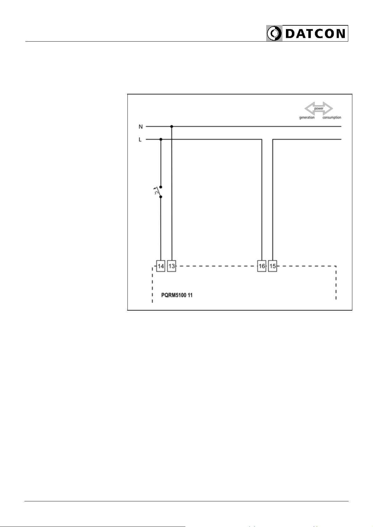
5.2. Connecting the measuring inputs to power network
(1ph, 2w, 1m)
The following figure shows the wiring plan, connecting the
instrument to low voltage power network.
Wiring plan, connecting
the voltage and current
inputs to power network
1. Loosen terminal screws.
2. Insert the wire ends into the open terminals according to
the wiring plan.
3. Screw the terminal in.
4. Check the hold of the wires in terminals by pulling on
them firmly.
Checking the
connections
Check if the cables are connected properly (have you
connected all the cables, have you connected to the right
place, do not the cable-ends touch each other).

PQRM5100 11 Ux Ix xx xx (PS)
14 20200205-V1
5.3. Connecting the measuring inputs to power network
trough CT (1ph, 2w, 1m)
The following figure shows the wiring plan, connecting the
instrument to low voltage power network.
Wiring plan, connecting
the voltage and current
inputs to power network
The terminal “k” of CT you
have to connecting to
earth!
1. Loosen terminal screws.
2. Insert the wire ends into the open terminals according to
the wiring plan.
3. Screw the terminal in.
4. Check the hold of the wires in terminals by pulling on
them firmly.
Checking the
connections
Check if the cables are connected properly (have you
connected all the cables, have you connected to the right
place, do not the cable-ends touch each other).

PQRM5100 11 Ux Ix xx xx (PS)
20200205-V1 15
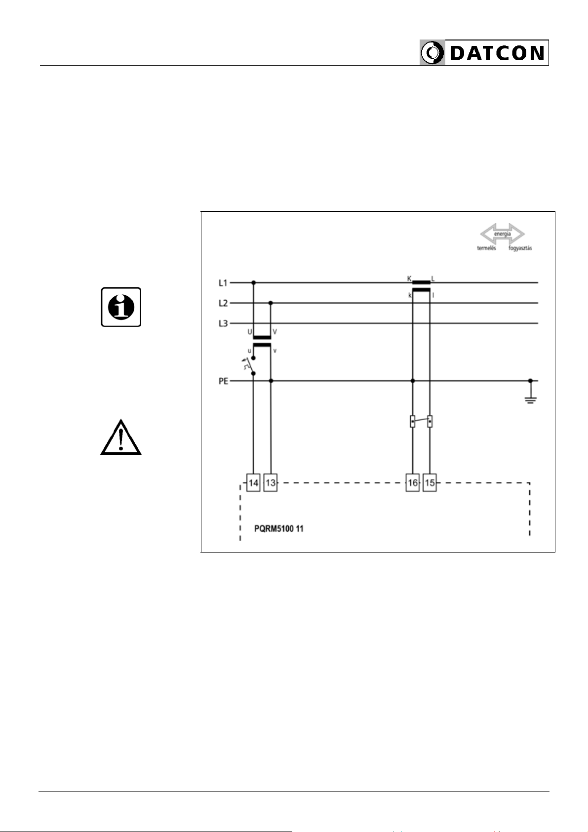
5.4. Connecting the measuring inputs to medium
power network. (1ph, 2w, 1m)
The following figure shows the wiring plan, connecting the
instrument to medium voltage power network.
Wiring plan, connecting
the voltage and current
inputs to power network.
The terminal “k” of CT and
terminal “v” of VT you have
to connecting to earth!
1. Loosen terminal screws.
2. Insert the wire ends into the open terminals according to
the wiring plan.
3. Screw the terminal in.
4. Check the hold of the wires in terminals by pulling on
them firmly.
Checking the
connections
Check if the cables are connected properly (have you
connected all the cables, have you connected to the right
place, do not the cable-ends touch each other).

PQRM5100 11 Ux Ix xx xx (PS)
16 20200205-V1
5.5. Connecting the measuring inputs to symmetrical
three-phase power network with neutral conductor.
(3 phase, 4 wire, 1 measuring)
The following figure shows the wiring plan to symmetrical
three-phase network. Measuring only one phase. The three
phase outputs are calculated values. The measuring
arrangement use for the measurement of rotating
machinery!
Wiring plan, connecting
the voltage and current
inputs to power network.
The application of:
The vectorsum of all phase
voltages is always zero!
The terminal “k” of CT and
terminal “v” of VT you have
to connecting to earth!
1. Loosen terminal screws.
2. Insert the wire ends into the open terminals according to
the wiring plan.
3. Screw the terminal in.
4. Check the hold of the wires in terminals by pulling on
them firmly.
Checking the
connections
Check if the cables are connected properly (have you
connected all the cables, have you connected to the right
place, do not the cable-ends touch each other).
PQRM5100 11 Ux Ix xx xx (PS)
20200205-V1 17
5.6. Connecting the measuring inputs to symmetrical
three-phase power network without neutral
conductor. (3 phase, 3 wire, 1 measuring)
The following figure shows the wiring plan to symmetrical
three-phase network without neutral conductor. Measuring
only one phase. The three phase outputs are calculated
values. The measuring arrangement use for the
measurement of rotating machinery!
Wiring plan, connecting
the voltage and current
inputs to power network.
The application of:
The vector sum of all
phase voltages is always
zero!
The terminal “k” of CT and
terminal “v” of VT you have
to connecting to earth!
1. Loosen terminal screws.
2. Insert the wire ends into the open terminals according to
the wiring plan.
3. Screw the terminal in.
4. Check the hold of the wires in terminals by pulling on
them firmly.
Checking the
connections
Check if the cables are connected properly (have you
connected all the cables, have you connected to the right
place, do not the cable-ends touch each other).
PQRM5100 11 Ux Ix xx xx (PS)
18 20200205-V1
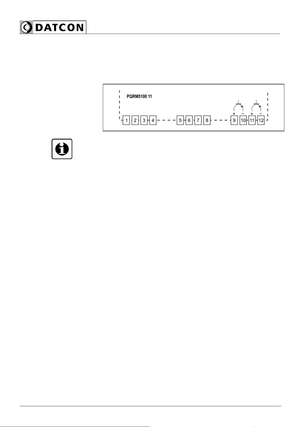
5.7. Connecting the digital outputs
The digital outputs of the device are passive switch
transistor. The external power supply is required for
operation. The figure shows the outputs terminal of the
switching transistor
Output terminal of the
digital outputs
The technical parameters of the digital outputs refer to the
9.1. chapter.
PQRM5100 11 Ux Ix xx xx (PS)
20200205-V1 19
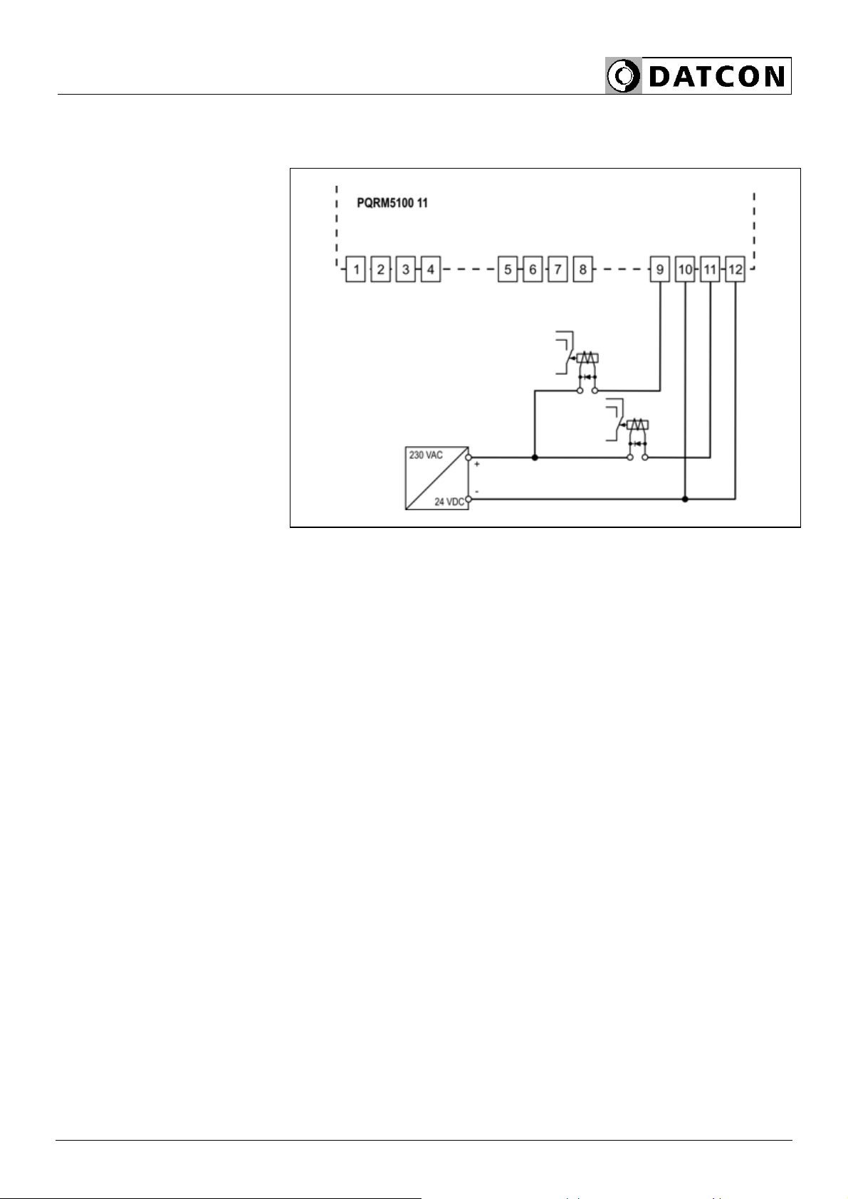
Example: Connect the digital output for processing unit.
Wiring plan, connecting
to processing unit.
Be careful the polarity of
the cables!
1. Loosen terminal screws.
2. Insert the wire ends into the open terminals according to
the wiring plan.
3. Screw the terminal in.
4. Check the hold of the wires in terminals by pulling on
them firmly.
9 -10 : digital output 1
11 - 12 : digital output 2
Checking the
connections
Check if the cables are connected properly (have you
connected all the cables, have you connected to the right
place, do not the cable-ends touch each other).
PQRM5100 11 Ux Ix xx xx (PS)
20 20200205-V1
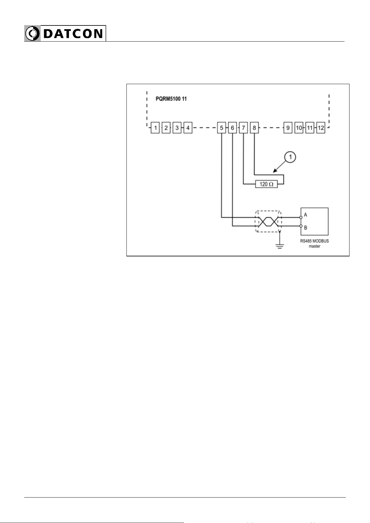
5.8. Connecting to MODBUS RS485 network
The following figure shows the wiring plan, connecting the
devices with MODBUS RS485 option to processing unit:
Wiring plan, connecting
to processing unit.
Be careful the polarity of
the cables!
1. Loosen terminal screws.
2. Insert the wire ends into the open terminals according to
the wiring plan.
3. Screw the terminal in.
4. Check the hold of the wires in terminals by pulling on
them firmly.
Checking the
connections
Check if the cables are connected properly (have you
connected all the cables, have you connected to the right
place, do not the cable-ends touch each other).
Table of contents
Other Datcon Transmitter manuals


