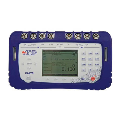
Datex-Ohmeda S/5 M-CAiOVX Use and care manual

Datex-Ohmeda Compact Airway modules
S/5TM Compact Airway Module, M-CAiOVX (rev. 01)
S/5TM Compact Airway Module, M-CAiOV (rev. 03)
S/5TM Compact Airway Module, M-CAiO (rev. 02)
S/5TM Compact Airway Module, M-COVX (rev. 02)
S/5TM Compact Airway Module, M-COV (rev. 03)
S/5TM Compact Airway Module, M-CO (rev. 02)
S/5TM Compact Airway Module, M-C (rev. 02)
Technical Reference Manual Slot
All specifications are subject to change without notice.
Document No. 800 1009-1
June 2001
Datex-Ohmeda Inc.
3030 Ohmeda Drive
53707-7550 MADISON, WIS
USA
Tel. +1-608-221 1551, Fax +1-608-222 9147
www.us.datex-ohmeda.com
Datex-Ohmeda Division,
Instrumentarium Corp.
P.O. Box 900, FIN-00031
DATEX-OHMEDA, FINLAND
Tel. +358 10 394 11 Fax +358 9 146 3310
www.datex-ohmeda.com
Instrumentarium Corp. All rights reserved.


Table of contents
Document No. 800 1009-1
i
TABLE OF CONTENTS
S/5 Compact Airway Modules
TABLE OF CONTENTS I
TABLE OF FIGURES III
INTRODUCTION 1
1 SPECIFICATIONS 2
1.1 General specifications ..............................................................................................................................2
1.2 Typical performance .................................................................................................................................2
1.2.1 CO2..................................................................................................................................................2
1.2.2 O2....................................................................................................................................................2
1.2.3 N2O .................................................................................................................................................2
1.2.4 Respiration Rate (RR) .......................................................................................................................3
1.2.5 Anesthetic Agents (AA)......................................................................................................................3
1.2.6 MAC ................................................................................................................................................3
1.3 Gas specifications ....................................................................................................................................3
1.3.1 Normal conditions............................................................................................................................4
1.3.2 Conditions exceeding normal............................................................................................................4
1.4 Patient spirometry specifications...............................................................................................................5
1.4.1 Normal conditions............................................................................................................................5
1.4.2 Conditions exceeding normal............................................................................................................6
1.5 Gas exchange specifications .....................................................................................................................7
1.5.1 VO2and VCO2...................................................................................................................................7
1.5.2 RQ ...................................................................................................................................................7
2 FUNCTIONAL DESCRIPTION 8
2.1 Measurement principle .............................................................................................................................8
2.1.1 CO2, N2O, and agent measurement ...................................................................................................8
2.1.2 O2measurement ............................................................................................................................10
2.1.3 Patient spirometry ..........................................................................................................................10
2.1.4 Gas exchange measurement...........................................................................................................12
2.2 Main components...................................................................................................................................13
2.2.1 Gas sampling system......................................................................................................................13
2.2.2 TPX measuring unit .........................................................................................................................17
2.2.3 OM measuring unit .........................................................................................................................17
2.2.4 PVX measuring unit.........................................................................................................................18
2.2.5 Gas exchange ................................................................................................................................19
2.2.6 CPU board .....................................................................................................................................19
2.2.7 OM board.......................................................................................................................................20
2.2.8 PVX board ......................................................................................................................................20
2.3 Connectors and signals...........................................................................................................................21
3 SERVICE PROCEDURES 22
3.1 General service information.....................................................................................................................22
3.1.1 OM measuring unit .........................................................................................................................22
3.1.2 TPX measuring unit .........................................................................................................................22
3.1.3 OM, TPX, and PVX measuring unit ....................................................................................................22

Datex-Ohmeda S/5 monitors
Document No. 800 1009-1
ii
3.1.4 Serviceable or exchangeable parts..................................................................................................22
3.2 Service check.........................................................................................................................................23
3.2.1 Recommended tools ......................................................................................................................23
3.2.2 Recommended parts......................................................................................................................23
3.3 Disassembly and reassembly..................................................................................................................31
3.3.1 PVX unit .........................................................................................................................................31
3.3.2 Pump unit......................................................................................................................................31
3.3.3 CPU board .....................................................................................................................................31
3.3.4 Software of CPU board ...................................................................................................................32
3.3.5 Instructions after replacing software or CPU board ...........................................................................32
3.4 Adjustments and calibrations..................................................................................................................32
3.4.1 Gas sampling system adjustment ...................................................................................................32
3.4.2 Flow rate measurement ..................................................................................................................32
3.4.3 Flow rate adjustment......................................................................................................................33
3.4.4 Gas calibration...............................................................................................................................33
3.4.5 Flow calibration..............................................................................................................................33
4 TROUBLESHOOTING 34
4.1 Troubleshooting charts ...........................................................................................................................34
4.1.1 CO2measurement..........................................................................................................................35
4.1.2 Patient spirometry..........................................................................................................................36
4.1.3 Gas exchange ................................................................................................................................38
4.2 Gas sampling system troubleshooting .....................................................................................................39
4.2.1 Sampling system leak test..............................................................................................................39
4.2.2 Steam test for the NafionTM tubes....................................................................................................39
4.3 OM measuring unit troubleshooting.........................................................................................................40
4.4 TPX measuring unit troubleshooting.........................................................................................................40
4.5 PVX measuring unit troubleshooting ........................................................................................................40
4.6 CPU board troubleshooting .....................................................................................................................40
4.7 Error messages.......................................................................................................................................41
5SERVICEMENU 42
5.1 General menu ........................................................................................................................................43
5.2 Gases service menu ...............................................................................................................................44
5.3 Spirometry service menu ........................................................................................................................46
6 SPARE PARTS 48
6.1 Spare parts list .......................................................................................................................................48
6.1.1 M-C rev. 00, M-CO rev. 00, M-CAiO rev. 00, M-COV rev. 01, M-CAiOV rev. 01, M-COVX rev. 00 ..........48
6.1.2 M-CAiOVX rev. 00, M-CAiOV rev. 02, M-CAiO rev. 01, M-COVX rev. 01, M-COV rev. 02, M-CO rev. 01, M-
C rev. 01..................................................................................................................................................49
6.1.3 S/5 M-CAiOVX rev. 01, S/5 M-CAiOV rev. 03, S/5 M-CAiO rev. 02, S/5 M-COVX rev. 02, S/5 M-COV
rev. 03, S/5 M-CO rev. 02, S/5 M-C rev. 02 ..............................................................................................49
6.1.4 Front panel stickers........................................................................................................................49
6.1.5 S/5 stickers...................................................................................................................................50
6.1.6 Planned Maintenance (PM) Kits: .....................................................................................................51
7 EARLIER REVISIONS 52
APPENDIX A 53
SERVICE CHECK FORM A-1

Table of contents
Document No. 800 1009-1
iii
TABLE OF FIGURES
Figure 1 TPX sensor principle..............................................................................................................................8
Figure 2 Absorbance of N2O and CO2..................................................................................................................9
Figure 3 Infrared absorbance of AAs ...................................................................................................................9
Figure 4 O2measurement principle ..................................................................................................................10
Figure 5 Absorber ............................................................................................................................................14
Figure 6 Gas sampling system layout, M-C........................................................................................................15
Figure 7 Gas sampling system layout, M-CAiOV, M-CAiOVX, M-CAiO, M-COVX, M-COV, M-CO..............................16
Figure 8 Gas tubing layout ...............................................................................................................................16
Figure 9 TPX measuring unit .............................................................................................................................17
Figure 10 OM measuring unit .........................................................................................................................18
Figure 11 PVX measuring unit.........................................................................................................................18
Figure 12 Signal processing...........................................................................................................................19
Figure 13 Control logic...................................................................................................................................20
Figure 14 Calibration data stored in EEPROM..................................................................................................20
Figure 15 Module bus connector pin layout ....................................................................................................21
Figure 16 Pneumatic unit and reference gas connection block.........................................................................25

Datex-Ohmeda S/5 monitors
Document No. 800 1009-1
iv

Compact Airway modules
Document No. 800 1009-1
1
INTRODUCTION
This section provides information for maintenance and service of the S/5 Compact Airway
modules. The Compact Airway modules are double width plug-in modules. M-C, M-CO, M-COV, M-
COVX, M-CAiO, M-CAiOV, M-CAiOVX and M-CAiOVX/SERVICE are designed for use with the S/5
monitors. The modules provide airway and respiratory measurements.
Letters in the module name stand for:
M = plug-in module, C = CO2and N2O, O = patient O2, V = patient spirometry, X = gas exchange,
A = anesthetic agents, and i = agent identification
About M-CAiOVX/SERVICE module
The M-CAiOVX/SERVICE module is meant for service purposes only. It can be used as a loan
module if the module in the hospital should be sent to the factory for repair. The specifications that
apply to the M-CAiOVX apply also to the M-CAiOVX/SERVICE module. Module differences: the
colour of the front mask is green, the front panel has a “SERVICE” text and there are no front panel
keys equipped.
Table 1 Options for Compact Airway modules
Modules Parameters/measurements
CO2N2OO
2Anesthetic
agents
Agent ID Spirometry Gas
exchange
M-CAiOV
X
• • • • • • •
M-CAiO
V
••• • • •
M-CAiO • • • • •
M-CO
V
••• •
M-COV
X
• • • • •
M-CO •••
M-C • •
M-CAiOVX
/
SERVICE ••• • • • •
NOTE: Do not use identical modules in the same monitor simultaneously. The M-C, M-CO, M-COV,
M-COVX, M-CAiO, M-CAiOV, M-CAiOVX and M-CAiOVX/SERVICE are considered identical modules.
NOTE: The Compact Airway Module and Airway Module, G-XXXX, cannot be used simultaneously in
the same monitor.
NOTE: The Compact Airway modules cannot be used in the Extension Frame, F-EXT4.
NOTE: Anesthetic agents and N2O values are not displayed with Critical Care main software, but
when present in the module they are calculated for compensation of CO2and O2.

Datex-Ohmeda S/5 monitors
Document No. 800 1009-1
2
1SPECIFICATIONS
1.1 General specifications
Module size, W ×D ×H 75 ×228 ×112 mm, 2.9 ×9.0 ×4.4 in
Module weight 1.6 kg/3.7 lbs
Operating temperature +10...+40 °C
Storage temperature -25...+70 °C
Atmospheric pressure 666...1060 hPa /
(67...106 kPa)
(500...800 mmHg)
(666...1060 mbar)
Humidity 10...95 % non-condensing (in airway 0...100 %, condensing)
Power consumption 12.6 W Prms, 14.6 W momentary
Protection against electrical shock
Type BF
1.2 Typical performance
1.2.1 CO2
Measurement range 0...15 vol% (0...15 kPa, 0...113 mmHg)
Measurement rise time <400 ms typical
Accuracy ±(0.2 vol% +2 % of reading)
Gas cross effects <0.2 vol% (O2, N2O, anesthetic agents)
If CO2concentration is below 0.1%, 0.0% is displayed.
1.2.2 O2
Measurement range 0 to 100 vol%
Measurement rise time <400 ms typically
Accuracy ±(1 vol% +2% of reading)
Gas cross effects <1 vol%; anesthetic agents
<2 vol%; N2O
O2Fi-Et difference resolution 0.1 vol%
1.2.3 N2O
Measurement range 0 to 100 %; N2O
Measurement rise time <450 ms typically
Accuracy ±(2 vol% +2% of reading)
Gas cross effects <2 vol%; anesthetic agents

Compact Airway modules
Document No. 800 1009-1
3
1.2.4 Respiration Rate (RR)
Measurement range 4...60 breaths/min
Detection criteria 1 % variation in CO2
1.2.5 Anesthetic Agents (AA)
Measuring range
Hal, Enf, Iso 0 to 6 vol%
Sev 0 to 8 vol%
Des 0 to 20 vol%
Measurement rise time <400 ms typically
Accuracy ±(0.15 vol% +5% of reading)
Gas cross effects <0.15 vol% N2O
Resolution is two digits when the AA concentration is below 1.0 vol%.
If AA concentration is below 0.1 vol%, 0.0% is displayed.
Identification threshold 0.15 vol% typically
Identification time <20 s (for pure agents)
Mixture identification threshold for 2. agent:
0.2 vol% +10% of total conc.
1.2.6 MAC
Range 0...9.9 MAC
Equation:
100
OETN
x(AA)
%(ETAA)
=MAC(AA) 2%
+Formula 1
where x(AA): Hal=0.75 %, Enf=1.7 %, Iso=1.15 %, Sev=2.05 %, Des=6.0 %.
1.3 Gas specifications
Airway humidity 0...100 %, condensing
Sampling rate 200 ±20 ml/min. (sampling line 2-3 m, normal conditions)
Sampling delay 2.5 seconds typical with a 3 m sampling line
Total system response time 2.9 seconds typical with a 3 m sampling line, including sampling
delay and rise time
Display update rate breath-by-breath
Automatic compensation for pressure, CO2-N2O and CO2-O2collision broadening effect.
Warm up time 2 min. for operation with CO2, O2, and N2O
5 min. for operation of anesthetic agents
30 min. for full specifications
Autozeroing interval Immediately after ‘calibrating gas sensor’ and 2, 5, 10, 15, 30, 45,
60 minutes after start-up, then every 60 minutes

Datex-Ohmeda S/5 monitors
Document No. 800 1009-1
4
1.3.1 Normal conditions
Accuracy specifications apply in normal conditions (after 30 minutes warm-up period):
Ambient temperature 18...28 °C, within ±5 °C of calibration
Ambient pressure 500...800 mmHg, ±50 mmHg of cal.
Ambient humidity 20...80 % RH, ±20 % RH of cal.
Non-disturbing gases
−Ethanol C2H5OH(<0.3%)
−Acetone (<0.1%)
−Methane CH4(<0.2%)
−Nitrogen N2
−Carbon monoxide CO
−Nitric Oxide NO (<200 ppm)
−water vapor
Maximum effect on readings
−CO2 <0.2 vol%
−O2, N2O <2 vol%
−anesthetic agents <0.15 vol%
Effect of Helium decreases CO2readings <0.6 vol% typically
1.3.2 Conditions exceeding normal
Accuracy specifications under the following conditions; :
Ambient temperature 10...40 °C, within ±5 °C of calibration
Ambient pressure 500...800 mmHg, ±50 mmHg of calibration
Ambient humidity 10...98 % RH, ±20 % RH of calibration
During warm-up 2 to 10 minutes (anesthetic agents 5-10 minutes), under normal conditions
During warm-up 10 to 30 minutes, under normal conditions
Accuracy under different conditions (see above)
Condition and Condition
CO2±(0.3 vol% + 4 % of reading)
(at 5 vol% error ±0.5 vol%)
±(0.4 vol% + 7 % of reading)
(at 5 vol% error ±0.75 vol%)
O2±(2 vol% + 2% of reading) ±(3 vol% + 3% of reading)
N2O±(3 vol% + 3% of reading) ±(3 vol% + 5% of reading)
Agents: Hal, Enf, Iso,
Sev, Des
±(0.2 vol% + 10% of reading) ±(0.3 vol% + 10% of reading)

Compact Airway modules
Document No. 800 1009-1
5
1.4 Patient spirometry specifications
1.4.1 Normal conditions
Accuracy specifications apply in normal conditions (after 10 minutes warm-up period):
Ambient temperature 10...40 °C
Ambient pressure 500...800 mmHg
Ambient humidity 10...98 %RH
Airway humidity 10...100 %RH
Respiration rate 4...35 breaths/min (adults)
4...50 breaths/min (pediatric)
I:E ratio 1:4.5...2:1
Intubation tube 5.5...10 mm (adults), 3...6 mm (pediatric)
Airway pressures (Paw, Ppeak, Pplat, PEEPe, PEEPiStat, PEEPiDyn, Pmean)
Measurement range -20...+100 cmH2O
Resolution 0.5 cmH2O
Accuracy ±1 cmH2O
Airway flow
Measurement range 1.5...100 l/min (adults)
(for both directions) 0.25...25 l/min (pediatric)
Tidal volume
Measurement range 150...2000 ml (adults), 15...300 ml (pediatric)
Resolution 1 ml
Accuracy ±6 % or 30 ml (adult), ±6 % or 4 ml (pediatric)
Minute volume
Measurement range 2...20 l/min (adults), 0.5...5 l/min (pediatric)
Resolution 0.1 l/min
Compliance
Measurement range 4...100 ml/cmH2O (adult), 1...100 ml/cmH2O (pediatric)
Resolution 1 ml/cmH2O (adult), 0.1 ml/cmH2O (pediatric)
Airway resistance
Measurement range 0...40 cmH2O/ l/s
Resolution 1 cmH2O/ l/s

Datex-Ohmeda S/5 monitors
Document No. 800 1009-1
6
Other parameters
Specifications apply in conditions listed in patient spirometry specifications.
Dead space of the sensor
9.5 ml (adult), 2.5 ml (pediatric)
Resistance of the sensor
0.5 cmH2O @ 30 l/min (adult), 1.0 cmH2O @ 10 l/min (pediatric)
1.4.2 Conditions exceeding normal
Accuracy specifications under the following condition (during warm-up 2 to 10 minutes):
Airway Pressure(Paw)
Accuracy ±2 cmH2O
Tidal volume
Accuracy ±10 % or 100 ml (adult), ±10 % or 10 ml (pediatric)

Compact Airway modules
Document No. 800 1009-1
7
1.5 Gas exchange specifications
Mathemathical integration of airway flow and gas concentration for intubated, mechanically
ventilated and/or partly spontaneously breathing patients.
NOTE: These specifications apply only when a 2 meter gas sampling line is used, and a Y-piece
with a physical dead space less than 8 ml.
NOTE: These specifications only apply if the FiO2level delivered to the patient is varing by less than
0.2 % during the inspiratory cycle at the measurement point.
1.5.1 VO2and VCO2
Measurement range 50...1000 ml/min
Resolution 10 ml/min
Accuracy ±10 % or 10 ml; when FiO2<65 %
±15 % or 15 ml; when 65 % <FiO2<85 %
1.5.2 RQ
Measurement range 0.6...1.2
Resolution 0.05

Datex-Ohmeda S/5 monitors
Document No. 800 1009-1
8
2FUNCTIONAL DESCRIPTION
2.1 Measurement principle
2.1.1 CO2, N2O, and agent measurement
TPX is a side stream gas analyzer, measuring real time concentrations of CO2, N2O and anesthetic
agents (Halothane, Enflurane, Isoflurane, Desflurane, and Sevoflurane).
Thermopile
detectors
Temp sensor
Sample
gas in
Sample
gas out
Sample
chamber
Figure 1 TPX sensor principle
Anesthetic agents or mixtures of two anesthetic agents are automatically identified and
concentrations of the identified agents are measured. TPX also detects mixtures of more than two
agents and issues an alarm.
TPX is a nondispersive infrared analyzer, measuring absorption of the gas sample at seven infrared
wavelengths, which are selected using optical narrow band filters.
The infrared radiation detectors are thermopiles.
Concentrations of CO2and N2O are calculated from absorption measured at 3-5 µm.

Compact Airway modules
Document No. 800 1009-1
9
Figure 2 Absorbance of N2O and CO2
Identification of anesthetic agents and calculation of their concentrations is performed by
measuring absorptions at five wavelengths in the 8-9 µm band and solving the concentrations
from a set of five equations.
Figure 3 Infrared absorbance of AAs
The measuring accuracy is achieved utilizing numerous software compensations. The
compensation parameters are determined individually for each TPX during the factory calibration.

Datex-Ohmeda S/5 monitors
Document No. 800 1009-1
10
2.1.2 O2measurement
The differential oxygen measuring unit uses the paramagnetic principle in a pneumatic bridge
configuration. The signal picked up with a differential pressure transducer is generated in a
measuring cell with a strong magnetic field that is switched on and off at a frequency of 165 Hz.
The output signal is a DC voltage proportional to the O2 concentration difference between the two
gases to be measured.
Switched
magnetic
field
Mixture
out
Electromagnet
Microphone
Sample in
Reference in
Figure 4 O2measurement principle
2.1.3 Patient spirometry
In mechanical ventilation breaths are delivered to the patient by a ventilator with a proper tidal
volume (TV), respiration rate (RR), and inspiration / expiration ratio in time (I:E) determined by the
settings of the ventilator.
The Patient Spirometry monitors patient ventilation. The following parameters are displayed:
−Expiratory and inspiratory tidal volume (TV) in ml
−Expiratory and inspiratory minute volume (MV) in l/min
−Expiratory spontaneous minute volume in l/min
−Inspiration/expiration ratio (I:E)
Airway pressure
−Peak pressure (Ppeak)
−Mean airway pressure (Pmean); available only in S/5 Critical Care and Compact Critical Care
monitors
−End inspiratory pressure (Pplat)
−PEEPi, PEEPe; available only in S/5 Critical Care and Compact Critical Care monitors
−Total positive end expiratory pressure (PEEPtot); available only in S/5 Anesthesia and
Compact Anesthesia monitors
−Real time airway pressure waveform (Paw)
−Static Positive end expiratory pressures (Static PEEPiand Static PEEPe); available only in
S/5 Critical Care and Compact Critical Care monitors

Compact Airway modules
Document No. 800 1009-1
11
−Static Plateau pressure (Static Pplat); available only in S/5 Critical Care and Compact
Critical Care monitors
−Static Compliance (Static Compl); available only in S/5 Critical Care and Compact Critical
Care monitors
PEEP, Ppeak, Pmean, and Pplat are measured by pressure transducer on the PVX board. Atmospheric
pressure is used as a reference in measurement. The pressure measurement is made from the
airway part that is closest to the patient between patient circuit and intubation tube.
PEEPi=intrinsic PEEP, PEEPtot-PEEPe
Static pressure measurement maneuvres are automatically identified based on a increased zero
flow period at the end of the inspiration or expiration.
Static Compliance is calculated if Static PEEP and Static Pplat measurements were done within a 2
minutes period.
Airway flow
−Real time flow waveform (V')
−Compliance (Compl)
−Airway resistance (Raw)
−Pressure volume loop
−Flow volume loop
The measurement is based on measuring the kinetic gas pressure and is performed using the Pitot
effect. A pressure transducer is used to measure the Pitot pressure. The obtained pressure signal is
linearized and corrected according to the density of the gas. Speed of the flow is calculated from
these pressure values and TV value is then integrated. MV value is further calculated and averaged
using TV and RR (respiratory rate) values.
Compliance and airway resistance
Compliance is calculated for each breath from the equation
ei
plat PEEPPEEPP
TV
Compl −−
=exp Formula 2
Compliance tells how big a pressure difference is needed to deliver a certain amount of gas into
the patient.
The airway resistance, Raw, is calculated using an equation, that describes the kinetics of the gas
flow between the lungs and the D-lite. The equation states that the pressure at the D-lite can at any
moment of the breath be approximated using the equation
ie PEEPPEEPCompl
tVtVRaw
tp ++
+×
=)()('
)( Formula 3
where p(t), V’(t) and V(t) are the pressure, flow and volume measured at the D-lite at a time t, Raw is
the airway resistance, Compl is the compliance and PEEPe+PEEPiis the total positive end
expiratory pressure (PEEPtot).

Datex-Ohmeda S/5 monitors
Document No. 800 1009-1
12
D-liteTM
Patient Spirometry uses a specific sensor called D-liteTM flow sensor. Different types of the D-lite
sensors are available: adult sensor for measuring adults and pediatric sensor for children. Both are
available as reusable versions and D-lite sensor also for single use.
D-lite adapter is designed to measure kinetic pressure by two-sided Pitot tube. Velocity is
calculated from pressure difference according to Bernoulli's equation. Flow is then determined
using the calculated velocity.
v= 2dP×
ρ
(from Bernoulli's equation) Formula 4
F=v A×,
where:
F = flow (l/min), v = velocity (m/s), A = cross area (m2), dP = pressure difference (cmH2O),
ρ
= density (kg/m3)
Finally the volume information is obtained by integrating the flow signal.
2.1.4 Gas exchange measurement
The gas exchange measurement uses the D-liteTM flow sensor and the gas sampler.
The basic data which is needed to obtain O2consumption and CO2 production are volumes and
concentrations.
Concentrations have been corrected for delay and deformation during the transport of the gas
sample in a sidestream gas measurement sensor.
To obtain the amount of O2consumed in ml/min, the amount which is exhaled is subtracted from
the amount that is inhaled.
To obtain the amount of CO2producted in ml/min, the amount which is inhaled is subtracted from
the amount that is exhaled.
These amounts can be obtained by multiplying each measured volume piece (dv) by the
corresponding gas concentration:
dvfdvf OO ò
−
ò
exp
22
insp
=2
VO Formula 5
and
dvfdvf COCO ò
−
ò
inspexp
=2
VCO 22 Formula 6
Using inspiratory and expiratory minute volumes MViand MVeand volume-weighted inspiratory
concentrations fi and fe these equations can be rewritten as:
eOiO=2 MVfe-MVfiVO 22 ×× [ml/min] Formula 7

Compact Airway modules
Document No. 800 1009-1
13
iCOeCO=2 MVfi-MVfeVCO 22 ×× [ml/min] Formula 8
To obtain results which are less sensitive to errors in volume measurements, so-called Haldane
transformation is used. This means taking advantage of the fact that the patient is not consuming
nor producing nitrogen: the amount of nitrogen inhaled is equal to the amount
exhaled fiN2 ×MVi=feN2×MVe.
VO2and VCO2can then be written as:
iOHaldO2 )MVfef-(fi=VO 22 ×[ml/min] Formula 9
iCOCOHald2 )MVfi-fe(f=VCO 22×[ml/min] Formula 10
with
fHald = (1-fiCO2 – fiO2 – fiN2O - fiAne1 – fiAne2) / (1-feCO2 – feO2 – feN2O - feAne1 – feAne2)
EE=(5.5 ×VCO2) + (1.76 ×VO2) + (1.99 ×Un) [kcal/day] Formula 11
with Un=Urea Nitrogen Excretion = 13 g/day (for adults only).
2.2 Main components
The compact airway modules consist of:
•Gas sampling system
•TPX measuring unit
•OM measuring unit
•PVX measuring unit
•CPU board
•OM board
•PVX board
2.2.1 Gas sampling system
The sampling system takes care of drawing a gas sample to the analyzers at a fixed rate.
The gas sampling system samples the measured air to the module, and removes water and
impurities from it. A sampling line is connected to the water trap. The pump draws gas through the
sampling line to gas measuring units. After the measurements, the gas is exhausted from sample
gas out connector.
The M-COVX and M-CAiOVX modules have a different gas sampling system compared to the other
modules. A number of flow restrictors have been changed to create a bigger pressure difference
with ambient pressure in the gas sensors. The sample flow is however about the same (200
ml/min).
A bigger pressure difference makes the deformations of the gas concentration curves less sensitive
to high variations of the airway pressures thus meeting also the accuracy requirements of gas
exchange for these applications.

Datex-Ohmeda S/5 monitors
Document No. 800 1009-1
14
D-fendTM
The sample is drawn through a sampling line. Then gas enters the monitor through the water trap,
where it is divided into two flows, a main flow and a side flow. The main flow goes into the
analyzers. This flow is separated from the patient side by a hydrophobic filter. The side flow creates
a slight subatmospheric pressure within the D-fend water trap which causes fluid removed by the
hydrophobic filter to collect in the bottle.
Zero valve and absorber
The main flow passes through a magnetic valve before
proceeding to the analyzers. This valve is activated to establish
the zero points for the TPX and OM units. When the valve is
activated, room air is drawn through the absorber into the internal
system and the gas sensors. Paralyme is used as an absorbent.
Figure 5 Absorber
NafionTM tubes 1)
A nafion tube is used between the water trap and the zero valve to balance the sample gas
humidity with that of ambient air. The tube will prevent errors caused by the effect of water vapor on
gas partial pressure when humid gases are measured after calibration with dry gases. Another
nafion tube is used between the absorper and the pneumatic unit to prevent humidity caused by
absorb of CO2.
Gas analyzers
After the zero valve and nafion tube the gas passes through TPX and OM units. The oxygen sensor
has two inputs. One input accepts the main flow and the other draws in room air for reference. Both
gas flows exit from a single port.
Sample flow differential pressure transducer
The sample flow differential pressure transducer measures pressure drop across OM inlet restrictor
and calculates sample flow from the pressure difference.
Working pressure transducer
The working pressure transducer measures absolute working pressure between the TPX unit and
OM unit. It is used for messages: ‘sample line blocked’, ‘check D-fend’, ‘replace D-fend’ and
‘check sample gas outlet’.
1) Nafion is a trademark of Perma Pure Inc.
This manual suits for next models
6
Table of contents


