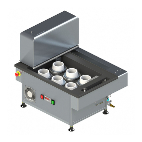
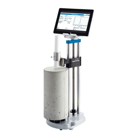
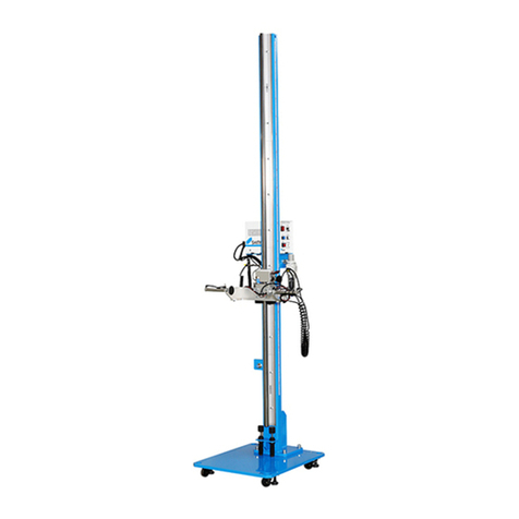
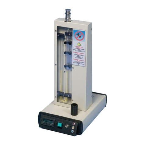
TESTING Vicat User manual

TESTING Bluhm & Feuerherdt GmbH
Manufacture and Distribution of
Testing Equipment for Construction Materials
Motzener Str. 26b
DE-12277 Berlin
Tel. +49(0)30/710 96 45-0
Fax +49(0)30/710 96 45-98
www.testing.de
1
Operating Manual
Single Station Vicat Needle Testing Apparatus

Single Station Vicat Test Apparatus
1.0360
2
CAUTION: Do not place this device into operation until you have made yourself fully acquainted with its
connection, with its function, and with the position of all its control elements and functions.
Contents Page
1. Basic instructions...................................................................................................................4
1.1 Designation................................................................................................................................................................4
1.2 Purpose for which this system was designed .............................................................................................................4
1.3 Improper use and safety notices ................................................................................................................................4
1.4 Guarantee..................................................................................................................................................................6
1.5 Acceptance of delivery and transport .........................................................................................................................6
1.5.1 Acceptance of delivery...............................................................................................................................................6
1.5.2 Transport ...................................................................................................................................................................6
1.5.3 Commissioning..........................................................................................................................................................7
1.6 Scope of delivery .......................................................................................................................................................7
1.7 Connection to the power supply.................................................................................................................................8
2. Apparatus properties..............................................................................................................9
3. Operation...............................................................................................................................10
3.1 Commissioning........................................................................................................................................................10
3.1.1 Connections and switching on..................................................................................................................................10
3.2 Modes of operation..................................................................................................................................................12
3.3 Setting options.........................................................................................................................................................13
3.3.1 Choice of a language...............................................................................................................................................14
3.3.2 Setting the brightness ..............................................................................................................................................14
3.4 Setting the parameters for water temperature control...............................................................................................15
3.4.1 Setting the set point for the heating..........................................................................................................................15
3.4.2 Setting the Hysteresis for the heating.......................................................................................................................16
3.4.3 Setting the set point for the cooling ..........................................................................................................................16
3.4.4 Setting the hysteresis for the cooling........................................................................................................................16
3.4.5 Setting the correction factor for sensor T1................................................................................................................17
3.5 Explanation of the process of water temperature control..........................................................................................18
3.6 Setting the parameters for the airflow control ...........................................................................................................19
3.6.1 Setting the upper temperature of heat sinks.............................................................................................................20
3.6.2 Setting the lower temperature of heat sinks..............................................................................................................20
3.6.3 Setting the run-on temperature of the heat sinks......................................................................................................20
3.6.4 Setting the correction factor for sensor T2................................................................................................................20
3.6.5 Stop running fans.....................................................................................................................................................21
3.7 Settings for the humidity sensor...............................................................................................................................22
3.7.1 Adjusting the slope of the humidity sensor ...............................................................................................................23
3.7.2 Adjusting the zero voltage of the humidity sensor.....................................................................................................23
3.7.3 Adjusting the offset of the humidity sensor...............................................................................................................24
3.8 Settings for the Vicat device.....................................................................................................................................25
3.8.1 Choosing cleaner device..........................................................................................................................................25
3.8.2 Setting the cleaner device position...........................................................................................................................26
3.8.3 Setting the samples center Y-coordinate..................................................................................................................27
3.8.4 Setting the samples zero level..................................................................................................................................29
3.8.5 Setting the Penetration time.....................................................................................................................................31
3.9 The monitoring page................................................................................................................................................32
4. Operation...............................................................................................................................35
4.1 Software ..................................................................................................................................................................35
4.2 Insert a sample ........................................................................................................................................................36
4.3 Starting a measurement on EN device.....................................................................................................................37
4.4 Starting a measurement on ASTM-device................................................................................................................38
5. Maintanace.............................................................................................................................39
5.1 Adjustment of the rubber buffer................................................................................................................................39
5.2 Replacing the brushes .............................................................................................................................................40
5.3 Replacing the needle ...............................................................................................................................................41
5.4 Replacing the seal ring.............................................................................................................................................42
6. After-sales service................................................................................................................43
6.1 Date of this version of the Operating Manual............................................................................................................43
6.2 Copyright .................................................................................................................................................................43
6.3 Spare parts and technical support............................................................................................................................43

Single Station Vicat Test Apparatus
1.0360
3
List of Figures Page:
Figure 1: Connections ....................................................................................................................................8
Figure 2: penetration patterns ........................................................................................................................9
Figure 3: modes of operation........................................................................................................................12
Figure 4: “TESTING” logo.............................................................................................................................12
Figure 5: setting options...............................................................................................................................13
Figure 6: choice of a language.....................................................................................................................14
Figure 7: setting the brightness....................................................................................................................14
Figure 8: parameters for water temperature control.....................................................................................15
Figure 9: setting set point heating ................................................................................................................15
Figure 10: setting hysteresis heating............................................................................................................16
Figure 11: setting correction factor for sensor T1 ........................................................................................17
Figure 12: Temperature control....................................................................................................................18
Figure 13: parameters for the airflow control................................................................................................19
Figure 14: Upper temperature of the heat sinks...........................................................................................20
Figure 15: parameters of the humidity sensor..............................................................................................22
Figure 16: Adjusting the slope of the humidity sensor .................................................................................23
Figure 17: Adjusting the zero voltage of the humidity sensor ......................................................................23
Figure 18: Adjusting the offset of the humidity sensor .................................................................................24
Figure 19: Settings for the Vicat device........................................................................................................25
Figure 20: Choosing cleaner device.............................................................................................................25
Figure 21: Hint for cleaner device position...................................................................................................26
Figure 22: Cleaner device position...............................................................................................................26
Figure 23: Hint for samples cencer ..............................................................................................................27
Figure 24: Setting the Y-coordinate of samples center................................................................................28
Figure 25: Hint samples zero level...............................................................................................................29
Figure 26: Determine zero level ...................................................................................................................30
Figure 27: Course of the zero level measurement.......................................................................................30
Figure 28: Zero level determination finished ................................................................................................30
Figure 29: Setting the penetration time ........................................................................................................31
Figure 30: monitoring page...........................................................................................................................32
Figure 31: VicatMPM application software...................................................................................................35
Figure 32: Fixing the sample on a measuring station ..................................................................................36
Figure 33: Cleaning device for needle..........................................................................................................37
Figure 34: Adjustment of the rubber buffer...................................................................................................39
Figure 35: Replacing the brushes of device cleaner for needle...................................................................40
Figure 36: Replacing the needle ..................................................................................................................41
Figure 37: Replacing the seal ring................................................................................................................42

Single Station Vicat Test Apparatus
1.0360
4
1. Basic instructions
1.1 Designation
Designation of the device: Please see the nameplate on the Vicat Apparatus, which shows the
complete characteristic data and the electric properties of the sys-
tem.
1.2 Purpose for which this system was designed
This Operating Manual contains the information required for operation of the products described here, for
the purpose for which they have been designed. This Operating Manual is intended to be used only by
technically qualified staff.
“Technically qualified staff” is defined as those persons who – as a result of their training; their experience;
the instructions which they have received; as well as their knowledge of the relevant standards, regulations,
accident-prevention regulations, and conditions of product operation in the company –have been authorized
by the person responsible for the safety of the company equipment to carry out the activities and actions
required for operation of the equipment described below, and who can recognize and prevent any possible
dangers arising from such operation (this definition of technically qualified staff has been provided in IEC
364).
The User must, by all means observe the requirements and limit values, as well as all safety instructions,
given in this Operating Manual. Any use of this device not in conformity with these stipulations shall be
considered to be in violation of the use for which this system was intended. If this device must operate under
special conditions, or with special modes of operation, then this shall be authorized only after consultation
with the manufacturer, and after obtaining his prior and express approval.
The apparatus serves exclusively to measure the setting times of cement. The beginning and end of the
setting process are determined from the way in which a steel needle penetrates into a cement sample man-
ufactured under specific conditions.
Caution!
The instructions provided in this operating manual concern only the correct use of the
system. To perform the test correctly, the user must observe the specific norms for
the test.
1.3 Improper use and safety notices
The apparatus is built according to the state of the art and recognised technical rules. Despite this, dangers
to life and limb of the user or third parties or damage to parts of the apparatus or other property can arise
during operation.
Do not disassemble the apparatus and do not attempt to repair or modify it.
Operate the product within the specified supply voltage range.
Do not operate the product in places exposed to icing, heat radiation, condensation, corrosive gasses, vi-
brations or heavy blows, and places with high air humidity and temperature fluctuations.
Caution
The mixing of cement with water causes the release of alkaline substances. In work-
ing with concrete, it is essential to take all necessary precautions to prevent dry ce-
ment from entering the eyes, mouth, or nose. Use protective clothing to prevent skin
contact with wet cement or concrete. If cement or concrete enters the eyes, immedi-
ately and carefully wash out the eyes with clean water. Seek medical help instantly.
If moist concrete contacts the skin, wash it off immediately.

Single Station Vicat Test Apparatus
1.0360
5
The operator must make sure not to endanger other persons. Only trained operators may use the device
unsupervised.
If any faults or damage to the apparatus impairs its operational safety, put it out of operation immediately
and use it again after you eliminate all hazards.
This operating manual contains safety instructions that you have to observe in order to exclude any risk of
fatalities, injuries, damage to the equipment or improper operation. Safety markings are as follows:
Caution!
This warning refers to dangers that could cause material damage.
Danger
This warning refers to dangers that could cause severe injuries or even fatalities.
Note
Provides practical advice on operation

Single Station Vicat Test Apparatus
1.0360
6
1.4 Guarantee
Apply our General Terms of Sales and Delivery in all cases.
The Manufacturer guarantees that this Operating Manual has been prepared in conformity with the technical
and functional parameters of the equipment as delivered. The Manufacturer reserves the right to add sup-
plementary information to this Operating Manual as required.
The guarantee provided by the Manufacturer is the legal guarantee. This guarantee does not cover wear-
and-tear parts.
The Manufacturer guarantees trouble-free operation only if the User observes the instructions in this Oper-
ating Manual, and only if the User employs the equipment for the purpose for which it is intended.
The Manufacturer shall not be liable for damages that may occur if the equipment is used for purposes for
which it is not intended, or if the User does not observe the instructions and rules for operation as set forth
in this Operating Manual.
No claims for damages may be lodged against the Manufacturer if the equipment is modified in its structural
or constructional characteristics without the prior written consent of the Manufacturer, or if its functional
characteristics are modified without such consent.
1.5 Acceptance of delivery and transport
1.5.1 Acceptance of delivery
When accepting delivery of the equipment, first inspect it for its outer, visible condition. If this inspection is
satisfactory, the device may be accepted from the freight forwarder (railways, parcel service, or other haul-
age company).
If there are no shortcomings, and if there are no transport damages, then use the bill of delivery to make
sure that the consignment is complete, and that all parts have been delivered.
If you assume or suspect transport damage, or if transport damage becomes apparent only after you have
accepted the delivery, immediately make an exact report of the conditions and any damage as they exist.
Send us this report immediately by fax or e-mail. Important: Absolutely do not make any changes to the
delivered goods.
After we have studied your report, we can make a decision whether we can:
•Deliver spare parts to you, or
•Send a specialized fitter/installer to your plant, or
•Ask that you return the system to us for repair.
1.5.2 Transport
The equipment is delivered in a transport box. The open spaces inside the boxes are filled with cushioning
material to prevent damage during transport.
After the equipment has been unpacked from the transport box, it can be lifted out of the box by hand and
moved by hand to the place where it is to be used.
The weight is approx. 22 kg.

Single Station Vicat Test Apparatus
1.0360
7
1.5.3 Commissioning
Place the equipment on an even and vibration-free base with a suitable load-bearing capacity. This equip-
ment is intended for operation in dry rooms.
The ambient conditions that must be observed are as follows:
Permissible temperature conditions:
+ 5 … 40°C
Permissible relative humidity:
30 ... 50%
Maximum elevation:
1,000 metres above sea level
Caution!
Take normal and reasonable precautions so that system does not suffer impacts or
is not damaged in another way.
1.6 Scope of delivery
The apparatus comes with the following standard accessories:
Power cord
RS232 cable
Handset unit
Hex key (SW 1.25 / SW: 2 for needle washing unit), (SW: 2 for cone washing unit)
Operating Manual for apparatus / Operating Manual for software
Table 1:
type of
machine
Vicat needlel
Vicat
rings
glass plates
spare
brushes
for needle
1.0360
1 station
cement
Ø1,13mm, 1 piece
+2 spare pieces
70/80 mm
1 piece
1 piece
+1 spare piece
1 pair
1.0360.ASTM
1 station
cement
Ø1,0mm 1piece
+2 spare pieces
60/70mm
1 piece
1 piece
+1 spare piece
1 pair
1.0360.EN/ASTM
1 station
cement
Ø1,13mm 1 piece
+2 spare pieces
Ø1,0mm, 3 pieces
70/80mm
1 piece
60/70mm
1 piece
1 piece
+1 spare pice
1 pair

Single Station Vicat Test Apparatus
1.0360
8
1.7 Connection to the power supply
Danger
In accordance with the pertinent standards, connect the socket to the earthing-sys-
tem.
Check the device rating plate to make sure that the ratings of the building power
supply conform to the requirements for voltage, wattage, amperage, and frequency
of the equipment.
The technical characteristics of this safety device must also satisfy the standards that
apply in the country in which the device is installed.
Caution
The manufacturer of the equipment is not be liable for any damages that result be-
cause of the information here is not observed.
Electrical tolerances:
Actual voltage: 10% of the rated voltage
Frequency: 1% of the rated frequency, continually; 2% of the rated frequency, on a short-term
basis
The manufacturer shall not be liable for damages to persons or properties that arise because the
above instructions have not been observed.
To protect the electronic components from short circuit, a troughs fuse (250VAC/ 3.6A) are build-in, easily
accessible to the user.
Figure 1: Connections
RS232 Connector to PC
Power supply
Power switch
Fuse

Single Station Vicat Test Apparatus
1.0360
9
2. Apparatus properties
The apparatus is classified among those that generally do not reach an acoustic emission of 90 dB(A)
(measured according to DIN 45 635).
The noise caused by the apparatus depends on various factors, such as installation site.
It is therefore impossible to state a general sound pressure level.
Technical Data:
Width/depth/height: 280 x 480 x 460 mm
Weight: approx: 22 kg
Electrical connection: 110–230 VAC / 50–60 Hz
Power draw: 200 W
Weight of drop rod: 300g ± 1 for cement
Additional weight: 700g ± 1 optional
Test cycles:
The apparatus supports various cycle times (0.5, 1, 2, 3, 5, 10, 20 and 30 min). According to the chosen
standard, the apparatus uses one of the following penetration patterns and the chosen cycle time to per-
form the test.
Figure 2: penetration patterns
Note
When in single range mode the check box “use minimum cycle time” is checked,
the apparatus uses minimum cycle time (0.5 min) as soon as the measured val-
ues approaches the ranges defined for initial time of setting and final time of set-
ting. Outside of ranges for initial time of setting and final time of setting, the appa-
ratus uses the chosen cycle time for the test.
26 penetrations (EN196-3) , (EN13454-2)
90 penetrations EN196-3)
43 penetrations (ASTM C191)
16 penetrations (EN196-3) , (EN13279-2)

Single Station Vicat Test Apparatus
1.0360
10
3. Operation
3.1 Commissioning
3.1.1 Connections and switching on
Plug the testing apparatus into the (110/230V 50/60Hz) mains using the supplied cord.
Switch ON the main switch on the rear of the device (Figure 1).
After switching ON the main switch, the control software runs through a standard initialization procedure that
concludes by determining the reference points (zero points) for each axis.
The control software also checks the needle for breakage and cleans it.
The unit is ready for use as soon as the page “monitoring appears.
The device is equipped with a touch screen. Use the touch screen for various settings of the device.
In order to parameterize and start a measurement, connect the device to the "VicatMPM" application on a
PC. Do it with the supplied serial cable, by connecting the RS232 socket on the rear of the device and the
USB adapter connector on the PC side.
For more information about how to perform a measurement, see "VicatMPM Software Manual".
The touch-display responds to the pressure of the finger or of a plastic pin.
Temperature control is off. Press to switch on the temperature controler.
Temperature control is on. Press to switch off the temperature controler.
Fan for the Run-ON Temperature of the heat sinks is off.
Fan for the Run-ON Temperature of the heat sinks is on.
Applies in all display views:
Press this button to return to the previous display page, here to (Figure 3
Applies in all display views:
Press this button to return directly to the paage with TESTING-logo (Figure 4).
Path line
monitoring
0 1 21.3 °C
0 sec 0.0 mm
VicatSPM is ready
Statu line

Single Station Vicat Test Apparatus
1.0360
11
* Installation of the USB-RS232-Adapter:
You will find the driver for the USB-RS232-adapter on the attached installation CD, if not automatically in-
stalled.
Windows:
To install the driver, you can use either:
a) the „CDM v2.10.00 WHQL Certified.exe“, that you will find on the CD in the folder according to your op-
erating system. Or
b) device manager. Right-click USB-Adapter and choose “install driver”.
Then click manual search for driver (NOT automatic search !!)
Choose on CD „ftdibus.inf“, according to your operating system.
Maybe you have to redo the procedure to install drivers for COM-Port (ftdiport.inf).
Note:
Communication via USB-RS232-Adapter to PC just works with properly installed drivers.
The number of the COM-Ports (here COM6) can vary.

Single Station Vicat Test Apparatus
1.0360
12
3.2 Modes of operation
In the settings mode, various parameters can be set for the display as well as for the Vicat device.
The monitoring mode allows the observation of the course of the measurement, as well as the ON/OFF
switching of the temperature control of the water bath.
Figure 3: modes of operation
Press button to return to the previous display page.
Press button to go directly to the page “TESTING” logo.
Press button to access the settings options.
Press button to activate the monitoring mode.
Figure 4: “TESTING” logo
Click on the upper left corner of the start page to go to the next display page (Figure 3).
settings
monitiring
Firmware: 201126 2.1
settings
Monitoring

Single Station Vicat Test Apparatus
1.0360
13
3.3 Setting options
Parameters can be set which affect the function of the touch display, the built-in sensors as well as the
function of the Vicat device itself.
These settings remain retained after switching off the unit.
Parameters for the touch-display:
language selection
Enabling/Disabling the buzzer function of the touch display
brightness adjustment of the display
Parameters for the temperature control of the water bath:
set point heating
hysteresis heating
set point cooling
hysteresis cooling
correction factor for the temperature sensor of the temperature control
Parameters for the airflow control:
upper temperature of the heat sinks
lower temperature of the heat sinks
run-on temperature of the heat sinks
correction factor for the temperature sensor of the airflow control
Parameters for the Vicat apparatus:
choice of the cleaner device (for needle or cone)
cleaner device position (Y-coordinate and Z-immersion deepness of the needle)
center of the sample (Y-coordinate)
zero level of the sample (surface of the glass plate)
penetration time of the needle
factory settings
Figure 5: setting options
Pressing button turns on the buzzer.
The button changes to
Pressing one of the other buttons will take you to another page to perform the desired action.
Enable buzzer
Disable buzzer
Enable buzzer
settings
language
Enable buzzer
Water
heating/cooling
brightness
Airflow control
Path of the view
Vicat device
humidity sensor
This button is visible only if a
humidity sensor installed pre-
viously.
"ASTM C191" option

Single Station Vicat Test Apparatus
1.0360
14
3.3.1 Choice of a language
As soon as you press a radio button assigned to the respective language, the display switches to the acti-
vated country language.
Figure 6: choice of a language
The selected language remains retained even after switching off the device.
3.3.2 Setting the brightness
Figure 7: setting the brightness
One-time short press of the button increases the brightness by 1%.
Pressing and hold down this button increases the brightness continuously until you release it or the bright-
ness has reached 100%.
One-time short press of the button decreases the brightness by 1%.
Pressing and hold down this button decreases the brightness continuously until you release it or the bright-
ness has reached 10%.
To get the set value also after switching off the device press the button.
Settings >Language
Deutsch
English
Française
This line shows the
path in the selected
language.
The chosen language
Pусский
Settings> Brightness
100 %

Single Station Vicat Test Apparatus
1.0360
15
3.4 Setting the parameters for water temperature control
Figure 8: parameters for water temperature control
Parameters for the temperature control of the water bath:
set point heating
hysteresis heating
set point cooling
hysteresis cooling
correction factor for the temperature sensor of the temperature control
Pressing one of the buttons (Figure 8) will take you to the page where you can edit the parameter.
3.4.1 Setting the set point for the heating
Figure 9: setting set point heating
One-time short press of the button increases the setpoint by 0.1 °C.
Pressing and hold down this button increases the set point continuously by 0.1 °C.
If you press and hold the button for more than 3 seconds, the step size increases to 1 ° C.
This process continues until you either release the button or you reach the maximum permissible value.
One-time short press of the button decreases the setpoint by 0.1 °C.
Pressing and hold down this button decreases the set point continuously by 0.1 °C.
If you press and hold the button for more than 3 seconds, the step size increases to 1 ° C.
This process continues until you either release the button or you reach the minimum permissible value.
To get the set value also after switching off the device press the button.
Settings> water heating/cooling>
setpoint heating
19.5 °C
settings> water heating/cooling
Correction factor
sensor T1
Setpoint
heating
Hysteresis
heating
Hysteresis
cooling
Setpoint
cooling

Single Station Vicat Test Apparatus
1.0360
16
3.4.2 Setting the Hysteresis for the heating
Figure 10: setting hysteresis heating
One-time short press of the button increases the hysteresis by 0.1 °C.
Pressing and hold down this button increases the hysteresis continuously by 0.1 °C.
If you press and hold the button for more than 3 seconds, the step size increases to 1 °C.
This process continues until either you release the button or you reach the maximum permissible value.
One-time short press of the button decreases the hysteresis by 0.1 °C.
Pressing and hold down this button decreases the hysteresis continuously by 0.1 °C.
If you press and hold the button for more than 3 seconds, the step size increases to 1 °C.
This process continues until you either release the button or you reach the minimum permissible value.
To get the set value also after switching off the device press the button.
3.4.3 Setting the set point for the cooling
Proceed as in the section (3.4.1).
3.4.4 Setting the hysteresis for the cooling
Proceed as in the section (3.4.2).
Settings> water heating/cooling>
hysteresis heating
0.5 °C

Single Station Vicat Test Apparatus
1.0360
17
3.4.5 Setting the correction factor for sensor T1
We use a TSIC306 temperature sensor for water temperature control.
The TSIC306 has a measuring range from -50 °C to 150 °C with a resolution of 0.1K.
The measuring accuracy is 0.3 K in the range 10 ... 90 °C and 0.5 K outside this range.
The correction factor adjusts the absolute temperature of the sensor to a more accurate referencing instru-
ment.
TRef = TSens correction factor
Pressing the button on the Settings>water heating/cooling page let you edit the
correction factor (Figure 11).
Figure 11: setting correction factor for sensor T1
One-time short press of the button increases the correction factor by 0.1 °C.
Pressing and hold down this button increases the correction factor continuously by 0.1 °C.
If you press and hold the button for more than 3 seconds, the step size increases to 1 °C.
This process continues until you either release the button or you reach the maximum permissible value.
One-time short press of the button decreases the correction factor by 0.1 °C.
Pressing and hold down this button decreases the correction factor continuously by 0.1 °C.
If you press and hold the button for more than 3 seconds, the step size increases to 1 ° C.
This process continues until you either release the button or you reach the minimum permissible value.
To get the set value also after switching off the device press the button.
Correction factor
sensor T1
Settings> water heating/cooling>
Correction factor sensor T1
21.3 °C
-0.1 °C
Temperature view of
the sensor T1

Single Station Vicat Test Apparatus
1.0360
18
3.5 Explanation of the process of water temperature control
The cooling process starts as soon as the water temperature reaches the value (set point cooling + hyste-
resis cooling) or rises above this value.
The cooling process stops only when the water temperature has declined to the value (set point cooling) or
if it has fallen below this value.
The heating process starts as soon as the water temperature reaches the value (set point heating - hyste-
resis heating) or falls below this value.
The heating process stops as soon as the water temperature rises to the value (set point heating) or if it
has exceeded this value.
The Figure below shows the graphical representation of the facts.
Setting values Process values
Figure 12: Temperature control
start cooling
stop cooling
hysteresis cooling 0.1 °C
set point cooling 20.0 °C
stop heating
set point heating 19.7 °C
start heating
stop heating
hysteresis heating 0.1 °C
actual value
start heating
20.1 °C
20.0 °C
19,7 °C
19,6 °C

Single Station Vicat Test Apparatus
1.0360
19
3.6 Setting the parameters for the airflow control
When the water bath is cooling, heat areises on the rear of the Peltier elements.
This heat must be dissipate.
For this purpose, the device is equipped with two heat sinks, which absorb the heat from the Peltier ele-
ments.
A temperature sensor detects the temperature of the heat sinks and controls thereby the airflow generated
by the fans.
The air stream transports the heat from the heat sinks into the environment.
The parameters listed below optimize the heat transfer.
Parameters for airflow control:
Upper temperature of the heat sinks
Lower temperature of the heat sinks
Run-on temperature of the heat sinks
Correction factor for the temperature sensor of the airflow control
Figure 13: parameters for the airflow control
At the upper temperature, the fans reach the maximum speed and thus produce the maximal airflow.
The lower temperature of the heat sinks determines the starting velocity and thus the minimum airflow.
In order to remove the excess heat the fans may continue to run until the heat sinks reach the run-on tem-
perature even after switching off the temperature-controller.
The correction factor adjusts the absolute temperature of the sensor to a more accurate referencing instru-
ment.
Press the desired button to go to the settings page of the parameter.
Settings> Airflow flow control
Upper
temperature of
the heat sinks
Correction factor of
sensor T2
Lower
temperature of
the heat sinks
Run-on
temperature of
the heat sinks

Single Station Vicat Test Apparatus
1.0360
20
3.6.1 Setting the upper temperature of heat sinks
Figure 14: Upper temperature of the heat sinks
One-time short press of the button increases the value by 0.1 °C.
Pressing and hold down this button increases the value continuously by 0.1 °C.
If you press and hold the button for more than 3 seconds, the step size increases to 1 °C.
This process continues until you either release the button or you reach the maximum permissible value.
One-time short press of the button decreases the value by 0.1 °C.
Pressing and hold down this button decreases the value continuously by 0.1 °C.
If you press and hold the button for more than 3 seconds, the step size increases to 1 ° C.
This process continues until you either release the button or you reach the minimum permissible value.
To get the set value also after switching off the device press the button.
3.6.2 Setting the lower temperature of heat sinks
Proceed as in the section 3.6.1).
3.6.3 Setting the run-on temperature of the heat sinks
Proceed as in the section 3.6.1).
3.6.4 Setting the correction factor for sensor T2
Proceed as in the section 3.4.5).
Settings> Airflow flow control>
Upper temperature of the heat sinks
60.0 °C
This manual suits for next models
1
Table of contents
Other TESTING Test Equipment manuals
