EnglishDeutsch
 logo
Brands
  1. Home
  2. •
  3. Brands
  4. •
  5. Anritsu
  6. •
  7. Test Equipment
  8. •
  9. Anritsu MT1000A Network Master Pro User manual

Anritsu MT1000A Network Master Pro User manual

Other manuals for MT1000A Network Master Pro

11

This manual suits for next models

1

Other Anritsu Test Equipment manuals

Anritsu Site Master S330A User manual

Anritsu

Anritsu Site Master S330A User manual

Anritsu MT8852B User manual

Anritsu

Anritsu MT8852B User manual

Anritsu Network master Pro User manual

Anritsu

Anritsu Network master Pro User manual

Anritsu Network Master Series User manual

Anritsu

Anritsu Network Master Series User manual

Anritsu VectorStar MN469 C Series User manual

Anritsu

Anritsu VectorStar MN469 C Series User manual

Anritsu Site Master S251B User manual

Anritsu

Anritsu Site Master S251B User manual

Anritsu MG369 A Series User manual

Anritsu

Anritsu MG369 A Series User manual

Anritsu MP1590B User manual

Anritsu

Anritsu MP1590B User manual

Anritsu MN469xC Series User manual

Anritsu

Anritsu MN469xC Series User manual

Anritsu MT8850A User manual

Anritsu

Anritsu MT8850A User manual

Anritsu MT1000A Network Master Pro User manual

Anritsu

Anritsu MT1000A Network Master Pro User manual

Anritsu Site Master S113B User manual

Anritsu

Anritsu Site Master S113B User manual

Anritsu MT8870A User manual

Anritsu

Anritsu MT8870A User manual

Anritsu SQA-R MP1900A Reference manual

Anritsu

Anritsu SQA-R MP1900A Reference manual

Anritsu OSL Series User manual

Anritsu

Anritsu OSL Series User manual

Anritsu 691 B Series User manual

Anritsu

Anritsu 691 B Series User manual

Anritsu InterferenceHunter MA2700A User manual

Anritsu

Anritsu InterferenceHunter MA2700A User manual

Anritsu CMA50 User manual

Anritsu

Anritsu CMA50 User manual

Anritsu BERTWave MP2100B User manual

Anritsu

Anritsu BERTWave MP2100B User manual

Anritsu Network Master Series User manual

Anritsu

Anritsu Network Master Series User manual

Anritsu MN469xC Series User manual

Anritsu

Anritsu MN469xC Series User manual

Anritsu OSL Series Use and care manual

Anritsu

Anritsu OSL Series Use and care manual

Anritsu MD1230B-26 User manual

Anritsu

Anritsu MD1230B-26 User manual

Anritsu MG3641A User manual

Anritsu

Anritsu MG3641A User manual

Popular Test Equipment manuals by other brands

SMART KANAAD SBT XTREME 3G Series user manual

SMART

SMART KANAAD SBT XTREME 3G Series user manual

Agilent Technologies BERT Serial Getting started

Agilent Technologies

Agilent Technologies BERT Serial Getting started

Agilent Technologies N3280A user guide

Agilent Technologies

Agilent Technologies N3280A user guide

Lifeloc R.A.D.A.R. quick start guide

Lifeloc

Lifeloc R.A.D.A.R. quick start guide

Fluke T5-600 Service information

Fluke

Fluke T5-600 Service information

Mercury TSL01 user manual

Mercury

Mercury TSL01 user manual

MAHA MBT Series Original operating instructions

MAHA

MAHA MBT Series Original operating instructions

Fuji Electric P-61 instruction manual

Fuji Electric

Fuji Electric P-61 instruction manual

ETC SealerAtor user manual

ETC

ETC SealerAtor user manual

Skyfine ETHYWAY V2 user manual

Skyfine

Skyfine ETHYWAY V2 user manual

Appion G5 Twin Operation manual

Appion

Appion G5 Twin Operation manual

PCB Piezotronics 8159-0112A Installation and operating manual

PCB Piezotronics

PCB Piezotronics 8159-0112A Installation and operating manual

BW Technologies MicroDock II user manual

BW Technologies

BW Technologies MicroDock II user manual

Sun Nuclear 1027 user guide

Sun Nuclear

Sun Nuclear 1027 user guide

Biomark HPR LITE READER user manual

Biomark

Biomark HPR LITE READER user manual

Hioki 3169-20 instruction manual

Hioki

Hioki 3169-20 instruction manual

Ashcroft ATE-100 operating manual

Ashcroft

Ashcroft ATE-100 operating manual

Rohde & Schwarz RTA4000 user manual

Rohde & Schwarz

Rohde & Schwarz RTA4000 user manual

https://manuals.online logo
https://manuals.online logoBrands
  • About & Mission
  • Contact us
  • Privacy Policy
  • Terms and Conditions

Copyright 2026 Manuals.Online. All Rights Reserved.

1. Port 1, Tx Bantam (DS1)
2. Port 1, Tx BNC (E1, E3, E4, DS3, STM-1e, STS-3)
3. Port 1, Rx Bantam (DS1)
4. Port 1, Rx BNC (E1, E3, E4, DS3, STM-1e, STS-3)
5. Port 2, Tx Bantam (DS1)
6. Port 2, Tx BNC (E1, E3, E4, DS3, STM-1e, STS-3)
7. Port 2, Rx Bantam (DS1)
8. Port 2, Rx BNC (E1, E3, E4, DS3, STM-1e, STS-3)
9. Port 1, Tx/Rx RJ48 (E1 balanced)
10. Port 2, Tx/Rx RJ48 (E1 balanced)
11. Port 1, Tx/Rx SFP/SFP+ (SDH / SONET / OTN / FC Ethernet optical)
12. Port 2, Tx/Rx SFP/SFP+ (SDH / SONET / OTN / FC Ethernet optical)
13. Port 1, Tx/Rx RJ45 (Ethernet electrical)
14. Port 2, Tx/Rx RJ45 (Ethernet electrical)
15. Audio 19. USB A
16. AUX 20. USB A
17. Clock input 21. Ethernet service interface
18. USB B 22. DC input (18 VDC)
Quick Reference Guide
MT1000A/MU100010A
Network Master Pro
Fourth Edition
Document No.: M-W3681AE-4.0
Additional safety and warning information is provided
within the “MT1000A/MU100010A Network Master
Pro” Operation Manual. Please refer to that document
before using the equipment.
Keep this manual with the equipment.
○
1
○
2
○
3
○
16
○
4
○
5
○
6
○
7
○
8
○
9 ○
10 ○
11 ○
12 ○
13 ○
14
○
15 ○
17 ○
18 ○
19 ○
20 ○
21 ○
22
Touch Screen display
Battery
Power button
Printed on Recycled Paper
Printed in Denmark
7
Network Master Pro is equipped with a touch screen display for operating the
instrument and test applications.
The power button also works as menu button when the instrument is turned on.
Power is supplied by an AC adopter or a 10.8V intelligent Li-Ion rechargeable and
replaceable battery, which is accessed from the side of the instrument. The battery
compartment door is secured with a lock screw.
Power Up/Power Down
To Power Up:
1. Press the Power button.
The Application Selector screen is displayed, where you can select to either start
an application or you can move to the Result File Browser screen to view the
results of a previous test.
To Power Down:
1. Press the Power button to launch the power-down menu.
2. Touch Shut Down in the menu.
3. Touch Yes in the “Shut Down Instrument” dialog box.
Forced Power Down:
Disconnect the main power adapter, and press and hold the Power button until the
instrument switches off.
Power Button Menu
The menu launched by the Power button when powering down has four menu items:
Apps Switcher – Displays the application switcher.
Capture Screen – Save an image in .PNG format of the
currently displayed screen.
Lock Screen – Locks or unlocks the screen.
Shut Down – Shuts down the instrument and turns
power off.
Advanced Use of Network Master Pro
Running multiple applications
It is possible to have multiple applications active simultaneously – assigned to different
ports. By displaying the application switcher, you can keep track of the progress of each
application and easily switch between them. You can access application switcher in
three ways.
By touching the application name or icon in the bottom of Port Setup, Test Setup
and Test Result screen
By touch and hold the Navigation button in the bottom of the Application selector
screen
From Power Button menu.
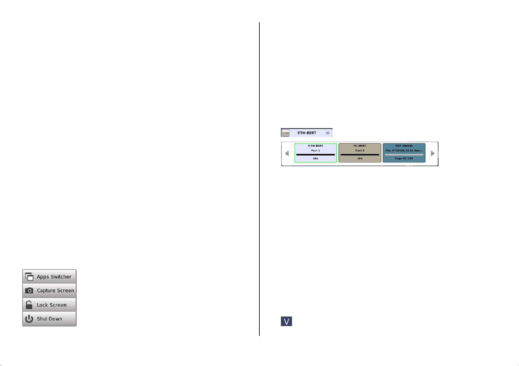
Navigation button
Application switcher
Saving interface/test configurations for future use
You can save partial and full configuration settings of interface and/or test parameters
for later re-use. The configuration is saved locally on the instrument where it is made,
but can be transferred to another instrument using a USB memory stick.
Language selection
You can select language of the GUI in the Language setup found in the instrument
toolbar.
Remote operation
You can operate MT1000A remotely from your PC using a browser or VNC.
You can use an Internet Browser or VNC tools to connect.
Instrument is connected on port 5800 for browser and port 5900 for VNC.
Browser requires Java version 7 or lower as Java 8 does not support access.
Browser Example: http://192.168.x.x:5800/
VNC Example: 192.168.x.x:5900
Touch the V icon to enable/disable remote access
6 3
General Functions
General functionalities such as insertion of stimuli, start/stop of test, creation of the
report etc. are placed in expandable toolbars. The GUI contains two such toolbars:
The instrument toolbar, which is available on all screens.
The application toolbar, which is available on the screens related to a specific
application.
The toolbar is placed on the right-hand side of the screen and is expanded/collapsed by
pressing an icon in the upper right-hand corner of the screen. Note that on the
application screens you can access the instrument toolbar from within the expanded
application toolbar.
Some of the functions available in the toolbars are:
Start
Instrument information
Stop Configuration
Traffic Start. File Manager
Traffic Stop
Help
Report
Resource monitoring
Error/Alarm Insert Close
Selecting Applications
A number of predefined applications are available – the types depending on which
options are installed in the instrument. You select the relevant application by touching
the corresponding icon on the Application Selector screen.
Displaying hidden icons
If an application row contains more application icons than can be displayed on the
screen initially, you can access the hidden icons by scrolling the relevant row.
Double-icons
Note that applications which can be run either with or without the OTN option are
represented by double-icons.
Touch the + OTN part of the icon to activate the application with the OTN option.
Starting an application
Touch the relevant application icon to start the application. Select the required Port(s)
by touching on the connectors on the connector image and touch Accept.
A green mark shows your selection. A red mark shows port selected by another
application.
4 5
Basic Screens and Navigation
Test Results
Application Selector screen Result Files Browser screen
Test Setup
Ports Setup
The GUI guides you through the setup and execution of the application, first
asking you to configure the related port(s), then to set up and run the actual
test. You go from one screen to the next by touching the tabs displayed in the
screen’s bottom corners.
You can, however, navigate freely both horizontally and vertically between the
various screens, as shown in the figure below.
Each screen contains a number of sub-screens, accessible via tabs or buttons
displayed at the top of the screen (in the “navigation area” of the screen).
On the Ports Setup screen, the buttons in the navigation area are related to
physical ports, signal layers etc. - activating sub-screens with the setup
parameters specific for that particular aspect of the port.
“Navigation area”