Powerfinn R3000 User manual

R1100R2300 R3000
Installation and User Manual
Robust Battery Chargers

Table of Contents
R1100 R2300 R3000........................................................................................................... 2
General ............................................................................................................................... 2
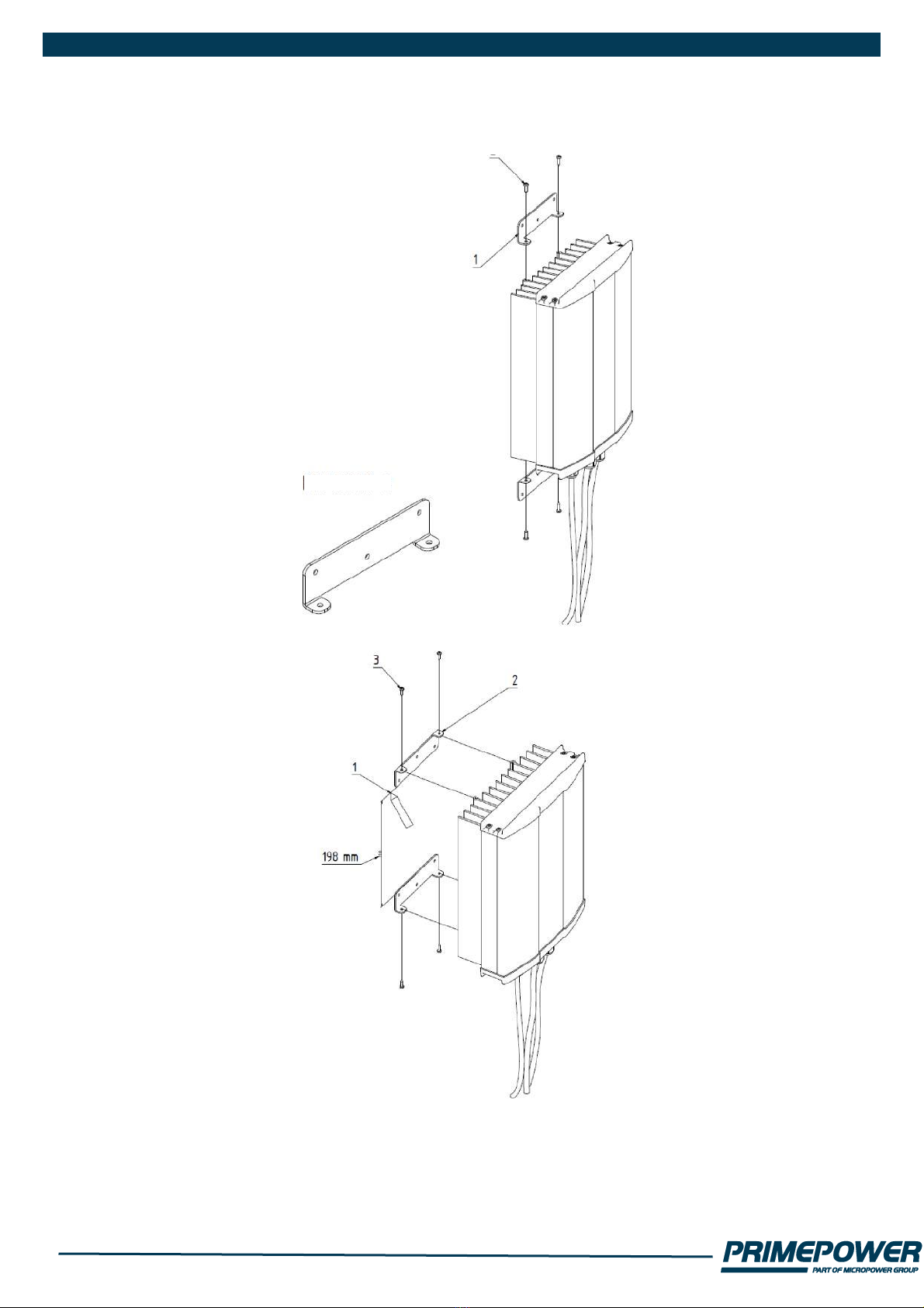
Installation and Warnings.................................................................................................... 3
Operations........................................................................................................................... 5
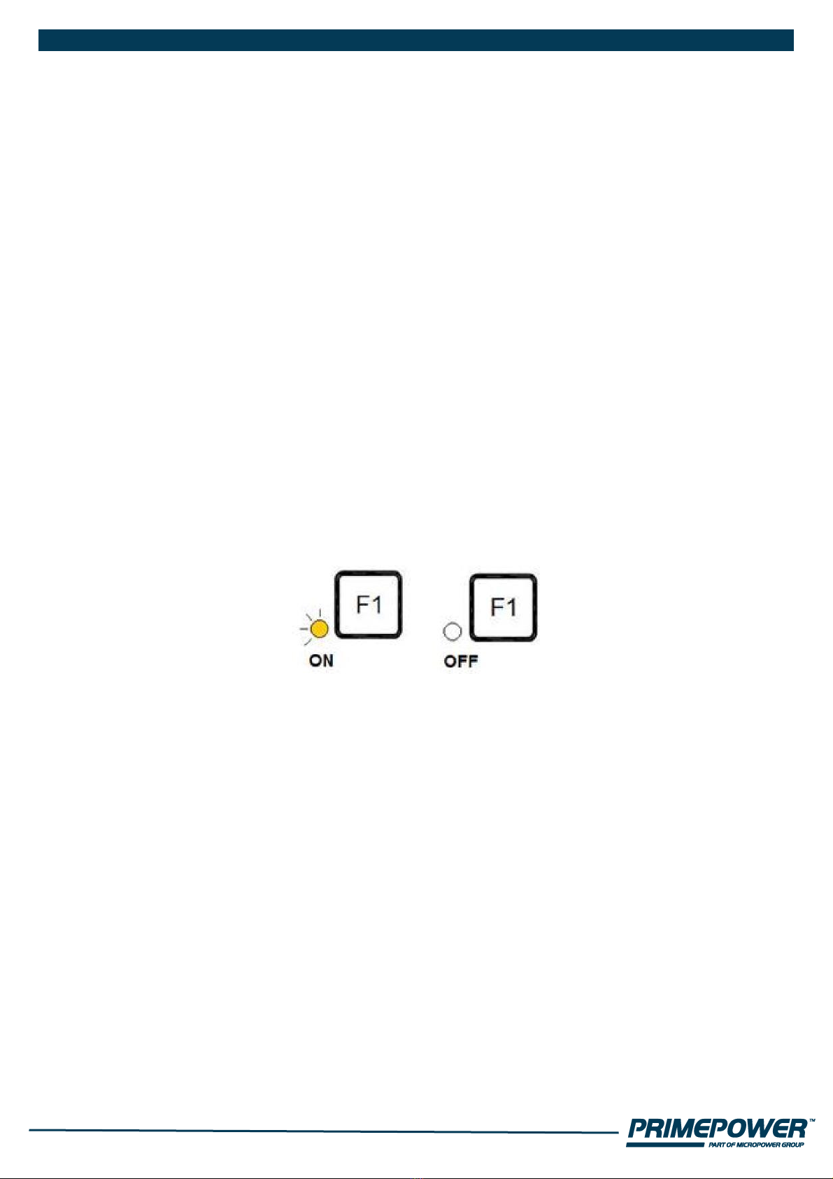
Lights and push buttons...................................................................................................... 6
Safety Instructions............................................................................................................... 8
Trouble–shooting and repair................................................................................................ 9
Guarantee ........................................................................................................................... 9
Editing charging configuration............................................................................................. 9
Connectors and pin orders:............................................................................................... 11
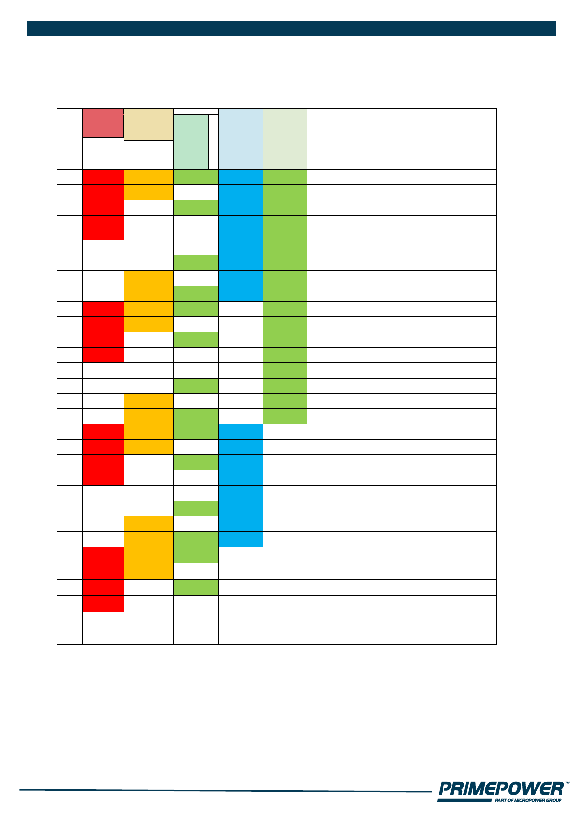
Algoritms ........................................................................................................................... 12
Charger dimensions.......................................................................................................... 15
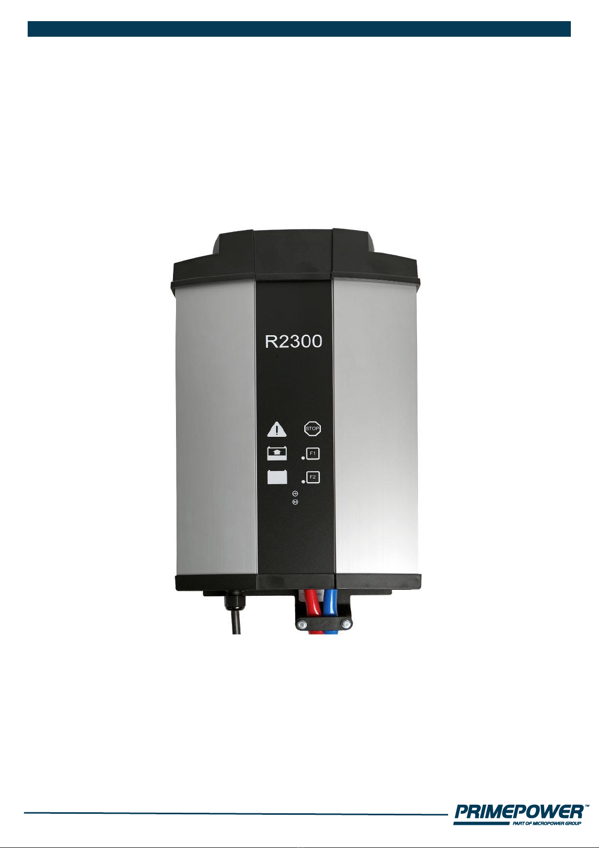
R1100 R2300 R3000
Primepower Robust series chargers uses modern switching technology. The
intelligent microcontroller extends the life of the battery by supervising the
charging process. The charger are compact, silent and meets the EU safety
and EMC requirements.
Protection class against water & dirt is IP54.
IP65 version is available
General
Chargers are available for a variety of battery types.
The charger type and charging algorithm should correspond to the battery
(sealed, vented, etc.). Attempting to charge a battery with the wrong type of
charger may result in considerable damage.
Find “Editing charging configuration paragraph” and ”Operations”.
Check the battery to ascertain that the “five hour capacity” (in ampere-hours,
Ah5 or Ah@5h) is between 5 and 14 times greater than the nominal current
(in amperes) of the charger. E.g. a 10A charger is suitable for charging
batteries with a 5-hour capacity of 50Ah-140Ah.

Installation and Warnings
The following points must be respected when choosing a location for the
charger.
1. In fixed installation the operation temperature range is -35°C to +55°.
Higher than +40° ambient temperature will limit the output power.
Caution: Mains cord & battery cable "indoor use" min temperature +5ºC. Do not bend in
cold environment.
2.The charger is to be installed vertically on a concrete or other non-
combustible surface only. For unplugging the unit, make sure the wall
socket is located in an easy access area.
3.To ensure sufficient ventilation, leave a free space of at least 10 cm around
all sides and 30 cm top and bottom of the charger. Do not cover the unit.
4.The charging process generates explosive hydrogen gas. Install the
charger as far away from the battery as possible to prevent hydrogen gases
from entering the charger. Keep the area well ventilated. Never use an open
flame or equipment that produces sparks close to the battery and charger.
5.Charger is to be installed vertically to a wall like shown in the next figures

BRACKET 2

Operations
Read these operating instructions carefully before using the charger for the
first time. Also read the safety instructions in the next paragraph thoroughly.
It must be ensured that children do not play with the device.
To charge a battery with ”Robust series” charger, follow these instructions:
Charger is configured with factory default settings. The factory default
setting is 12 cells algorithm LK10-06 freely ventilated, capacity 50 Ah.
Find “Editing charging configuration paragraph page 8”.
1.Ensure that the charger is unplugged and that the installation environment
meets the conditions described in the previous paragraph.
Warning: Explosive gases. Prevent flames and sparks. Provide
adequate ventilation during charging.
2.Connect the charger cables to the battery terminals: the positive (+) cable
to the positive (+) terminal and the negative (–) cable to the negative (–)
terminal. The positive cable is red colored. The negative cable is black or
blue.
3.Turn the power on by plugging the power cord in a mains outlet with
protective earth.
4. Charging starts automatically.
STOP
Pressing STOP will PAUSE charging. Pressing STOP again resumes
charging.
F1 and F2
F1 and F2 buttons can be assigned the various functionality. By default no
function is assigned. Pressing buttons while charging process does not
have any effect to charging. Buttons are used when battery settings will be
programmed. More details in section “Editing charging configuration”.
5.To avoid sparking in output cables, press STOP button before
disconnecting battery.

Lights and push buttons
Chargers front label should look following.
Main is connected.
Radio module is ON.
Charger can be assembled with optional radio module. Module allows access
to configuration and history log of the charger.

1. Indications and what they mean:

Safety Instructions
In addition to the safety measures mentioned under ‘Operations’ (page 5), the
following personal precautions should be taken whenever charging batteries.
1. For emergency situations ensure in advance that help is available in time
of need.
2. Batteries contain acid that is harmful to the eyes, skin and clothes. Always
wear overalls and safety goggles. Never touch the eyes with unwashed
hands after handling batteries.
3. Ensure that a working, fresh water tap is available. If acid gets intothe eyes
or on the skin, immediately rinse the area with plenty of water for several
minutes. If visible injury occurs, contact a physician immediately. In case
of eye injuries, always contact a physician.
4. The charging process generates explosive hydrogen gas. Do not smoke or
otherwise bring burning or sparking matter to the vicinity of the battery
when it is being charged.
5. If a short circuit occurs, the battery may explode or the item causing the
short circuit may melt. Keep the work area clear from tools and debris.
Remove jewelry, watches etcetera before working with the battery.
6. The power cord should be unplugged and the battery must be
disconnected from the charger in case the equipment is left unused for a
longer period of time.
7. The charger must locate away from heat sources like radiators and heat
registers.
8. This device is not meant to be used by children or people whose physical,
sensory or mental attributes or lack of experience and knowledge prevent
them from using the device safely unless a person responsible for their
safety supervises them or has instructed them how to use the device.

Trouble–shooting and repair
If the cause of malfunction cannot be found, contact your retailer or the
manufacturer. Only authorized persons can repair the charger.
Guarantee
The charger has a guarantee of two years from the date of purchase.
Guarantee covers manufacturing and component failures and is valid only if
the equipment is installed and used according to the instructions in this
manual.
Keep the receipt as evidence of the date of purchase.
Editing charging configuration
1.Disconnect battery.
2.Connect mains power.
3.As soon as blue LED is lit, press STOP for 10 s. LED's should flash shortly.
Release STOP. Special configuration mode has been entered.
4.To scroll down the list, press STOP.
5.To set item on/off, press F1. List of items are in table below.
6. After configuration has been set, disconnect mains power.

Following table equals with program version 11613002v02. Check the program
version from the charger labels! Bold text in coloured areas indicates LED
“ON”.
Blue/
Main
s
small
green/
Radio
item
Green/
Ready
Red
/
Erro
r
Yellow/
Charging
1
red
yellow
green
blue
s.green
algorithm LK10-06 freely ventilated
2
red
yellow
green
blue
s.green
algorithm LK10-04 wet puls
3
red
yellow
green
blue
s.green
algorithm LK20-09 valve ventilated
Sonnenschein
4
red
yellow
green
blue
s.green
algorithm LK10-05 wet with constant
current maintenance charging
5
red
yellow
green
blue
s.green
algorithm PP100 unsealed
6
red
yellow
green
blue
s.green
algorithm PP101 sealed
7
red
yellow
green
blue
s.green
algorithm PP102 Sonnenschein
8
red
yellow
green
blue
s.green
algorithm --
9
red
yellow
green
blue
s.green
capacity 50 Ah
10
red
yellow
green
blue
s.green
capacity 75 Ah
11
red
yellow
green
blue
s.green
capacity 100 Ah
12
red
yellow
green
blue
s.green
capacity 125 Ah
13
red
yellow
green
blue
s.green
capacity 150 Ah
14
red
yellow
green
blue
s.green
capacity 200 Ah
15
red
yellow
green
blue
s.green
capacity 250 Ah
16
red
yellow
green
blue
s.green
capacity 300 Ah
17
red
yellow
green
blue
s.green
capacity 350 Ah
18
red
yellow
green
blue
s.green
capacity 400 Ah
19
red
yellow
green
blue
s.green
capacity 450 Ah
20
red
yellow
green
blue
s.green
capacity 500 Ah
21
red
yellow
green
blue
s.green
capacity 550 Ah
22
red
yellow
green
blue
s.green
capacity 600 Ah
23
red
yellow
green
blue
s.green
capacity 700 Ah
24
red
yellow
green
blue
s.green
capacity 800 Ah
25
red
yellow
green
blue
s.green
Operation mode •-Charger •-Power supply
26
red
yellow
green
blue
s.green
External input •-Not Active •-Stop
27
red
yellow
green
blue
s.green
CAN-mode •-Master •-Master ext
28
red
yellow
green
blue
s.green
Reserved (Parallel operation)
29
red
yellow
green
blue
s.green
Reserved (BMU-unit control)
30
red
yellow
green
blue
s.green
Reserved

J-
Connectors
and pin
numbers
J-connector
cable
wire colors
HD26
Connector's
pin order
Operation
J23-1
black
4
LED green anode (10mA current source)
J23-2
red
22
LED common cathode (Same ground as is in battery minus)
J23-3
green
14
LED red anode (10mA current source)
J23-4
yellow
5
LED yellow anode (10mA current source)
J22-1
black
2
Sense plus (+)
J22-2
red
12
Battery temperature compensation (-) (Sensor: 2 series
connected Philips KTY83-120 sensors)
J22-3
green
3
Battery temperature compensation (+)
J22-4
yellow
20
Sense minus (-)
J21-1
black
19
External digital input (+)
(Signal send when shor-circuited between HD26 pin 11.
J21-2
red
1
CAN-bus Hi
J21-3
green
10
CAN-bus Lo
J21-4
yellow
11
External input (-)
J24-1
black
26
Relay Common (0.5A@125Vac, 2A@30VDC,
0.3A@110VDC)
J24-2
red
18
Relay Normally Open
J24-3
green
9
Relay Normally Closed
J24-4
yellow
Not connected
25
Isolated +5V, 5mA output
7
Isolated output ground (Same grouns as in HD26 pin 11)

Algorithms
LK10-06 freely ventilated (Temperature sensor supported)
LK10-04 wet puls (Temperature sensor supported)

LK20-09 valve ventilated Sonnenschein (Temperature sensor not supported)
LK10-05 wet with constant current maintenance charging (Temperature sensor supported)


Charger dimensions
Dimension drawing for R2300 / R3000 with fan.

Dimension drawings for R1100 with fan and R1100 without fan(passive cooling).

This manual suits for next models
2
Table of contents
Other Powerfinn Batteries Charger manuals

Powerfinn
Powerfinn R1100 User manual

Powerfinn
Powerfinn Robust 1100 Release Note

Powerfinn
Powerfinn PAC 1600 User manual

Powerfinn
Powerfinn PAC 600 User manual

Powerfinn
Powerfinn R1100 User manual

Powerfinn
Powerfinn R1100 User manual

Powerfinn
Powerfinn PAC 1600 User manual

Powerfinn
Powerfinn Robust 1100/24 User manual