ATESS EVD-300D User manual

+ 86 755 2998 8492
T
Shenzhen Atess Power Technology Co.,Ltd
3rd floor, building 9, Henglong industrial park, the fourth industrial zone of Shuitian community,
Baoan district, Shenzhen, China
E info@atesspower.com
Wwww.atesspower.com
DC quick charger User Manual
EVD-300D

Safety Precautions
Overview
1
Main function unit
introduction
2
Packaging, transportation
and storage
6
Parameter configuration
5
Ordering instructions
and after-sales service
7
Appendix
Operation Instructions
3
5.1 Safety check before use
7.1 Ordering note
7.2 After-sales service
7.3 Attachment list
Appendix I Technical standards and regulations
Appendix II Electrical Schematics
Installation
4
Contents
1.1 Product introduction
1.2 Product Block Diagram (two guns)
1.3 The main parameters
1.4 Product performance and features
1.5 Product use environment
1.6 Product Standards
2.1 Charging unit
2.2 Charger function introduction
3.1 Swipe card operation process
3.2 Mobile APP operation process
3.3 Operational precautions
3.4 Charge Status Description
3.5 Indicator light description
3.6 Emergency stop switch instructions
3.7 Common fault indications and solutions
4.1 Installation conditions
4.2 Charger installation
4.3 Cable connection

Safety Precautions
Before operating, please read the instruction manual carefully to understand the correct usage of
the equipment. Please read it completely and save properly for future reference.
In order to ensure the personal and property safety of the user at the time of installation of the
product, relevant information is provided in the manual and highlighted with appropriate
symbols. The following is a list of symbols that may be used in this manual. Please read these
instructions carefully to make better use of this manual.
2
Danger!
This means there is a high level of potential danger that could result in death or
serious injury if not avoided.
CAUTION
Indicates a potential risk that, if not avoided, may cause the device to
malfunction and a loss of property.
High voltage!
Touching may cause electric shock. The equipment contains AC and DC power
terminals, which must be disconnected from each power supply individually
and wait at least 5 minutes for service.
PE terminal
PE terminal must be firmly connected to earth to ensure the safety
of personnel.
1)Do not place dangerous items such as flammable, explosive or flammable materials, chemicals,
combustible vapors near the DC charger;
2)Keep the charging connector clean and dry, if dirty, please wipe it with a clean dry cloth,
Touching the conducting part of charging connector when charging is strictly prohibited;
3)It is strictly forbidden to use the charger if the following cases is found - charging connector or
charging cable defect, charging cables cracks, abrasion, rupture or exposed, etc. If found, please
contact the staff immediately;
4)Do not attempt to disassemble, repair or modify the product. No user serviceable
parts inside. Any such requirements please contact the staff, improper operation
will cause damage, water leakage or electricity leakage;
5)It is forbidden to unplug the charging connector during charging to ensure the safety of
personnel and vehicles.
6)In case of any unusual situation during the usage, immediately press the emergency button to
cut off all input and output power;
7)It is not suggested to charge in rain and thunder weather;
8)Children are not to approach the charger during charging process to avoid injury.
9)Please close the doors on both sides to avoid electric shock during charging.
10)During the charging process, the vehicle is prohibited from driving and can only be charged
when it is stationary. Engine must be turned off before charging hybrid vehicle.
1
Overview
1.1 Product introduction
The integrated dual-gun DC fast charger is mainly used for DC quick charging of electric vehicles.
This product integrates power conversion, charging control, human-computer interaction
control, communication and billing and metering, and has good dustproof and waterproof
functions, IP54 degree of protection, safe operation and maintenance outdoors. It is the best
choice for outdoor fast DC charging.
Fig1.1.1 outline drawing
1.1.1 Front panel introduction
Fig1.1.2 Front panel
1
1
2
3
4
5
6

This product is mainly composed of HMI touch screen,, electric energy metering module,
charging unit, communication module, charging interface, control module and pile body. It has
multiple protection functions, input and output with dual safety protection measures, Charging
cable connection status is monitored real-timely, charging is terminated immediately if
connection is abnormal, The emergency button can ensure the charger cease operation
immediately once abnormal is found to ensure safety. User-friendly interface display allows
customers to easily complete the charging process. The RS232port, Ethernet and other
communication interfaces allows real-time communication with monitoring center, operations
management center. Charging status can be monitored real-timely.
1-Connector A running/fault
indicator(running:Yellow;fault:Red)
2-Connector B running/fault
indicator(running:Yellow;fault:Red)
3-Power indicator Green
4- Emergency button
5-HMI
6-Cooling air inlet
1.2 Product Block Diagram (two guns)
1.3 The main parameters
Tab2: Technical Data Sheet
No.
1
2
3
4
5
6
7
8
9
10
11
12
13
14
15
16
17
18
19
20
21
Item
AC input voltage
AC input current
AC frequency
Power factor
Output voltage range
Voltage accuracy
Max DC output current per connector
Current accuracy
Voltage regulating accuracy
Current regulating accuracy
Ripple coefficient
Standby power consumption
Input inrush current
Output inrush voltage
Efficiency
Noise
DC charging metering accuracy
Dimension(W*D*H)
Weight
DC connection standard
DC plug type
Unit
V
A
Hz
V
%
A
%
%
%
W
A
V
%
dB
mm
KG
Standard value
AC 400: ±15%
440A
50±1
≥0.98
200-850
≤±0.5
DUAL PLUG 200A+200A
≥30A: ≤±1%
<30A: ≤±0.3A
≤±0.5%
≤±1%
RMS: ≤±0.5
Peak: ≤±1
≤0.1%Rated output power
≤120%Rated input current
≤110%Stable output voltage
≥94
≤65
0.5%
1190*1000*2195
IEC62196/IEC61851
CCS type2
1.4 Product performance and features
Product performance
1)High efficiency and low harmonics, A class quality
System efficiency ≥94%,industry-leading power density, low energy consumption, high energy
efficiency. Charging unit using active power factor correction technology, harmonic interference
≤ 5%, power factor up to 0.99.
43

2)Full protection, safe operation
It has multiple protection functions such as input / output protection, self-test, input over /
under-voltage protection, Output over-voltage / short-circuit protection, overheat / fault
protection of rectifier unit, insulation protection, connection monitoring and protection of
charger and battery. To ensure safe and reliable operation of the system, effectively preventing
accidents.
3)Wide voltage output, easy to use
According to different application needs, the output voltage is adjustable between 200V-850V,
wide voltage range to suit different battery charging needs, and different voltage level electric
vehicles.
Features:
Using high-efficiency, advanced DSP control technology.
Multi-function high accuracy DC meter, accurate measurement of the amount of energy
used.
Non-contact RF card. And the encryption and authentication of hardware level to ensure
account and data security.
Using 7-inch touch screen, showing the color glossy, Display can be clearly viewed even in
direct sunlight, the charger can adapt to environment temperature as low as -20 ℃.
Charging cable disconnection detection function, as well as charging cable cut detection
to ensure the safety of charging process and anti-theft features.
Via the real-time communication with monitoring platform, all data can be monitored and
recorded.
System software supports remote and local upgrade features.
1.5 Product use environment
Elevation ≤3000 meters
Equipment operating environment temperature -20 ℃ ~ 65 ℃
Relative humidity of air 5% ~ 95%
Over-head shelter is needed for outdoor installation.
Installation tilt does not exceed 5%
Keep away from flammable and explosive materials
1.6 Product Standards
Please refer to Annex2
2Main function unit introduction
2.1 Charging unit
The self-developed electric vehicle charging rectifier unit comes with DSP processor. The machine
parameters can be set or adjusted by the supervisory control unit via CAN interface. Use soft-
switching technology, high efficiency, good electromagnetic compatibility, built-in DSP control,
stable and reliable, wide input voltage range. With input over / under-voltage protection, output
over-current protection, output over-voltage protection, output short-circuit protection, over-
temperature protection and alarm function.
Charging unit technical parameters as follows:
No.
1. Input characteristic
1.1
1.2
1.3
1.4
1.5
1.6
2. Output characteristic
2.1
2.2
2.4
2.5
2.6
2.7
Item
Rated input voltage
AC input voltage range
Three-phase imbalance
Frequency
PF/THD
Efficiency
Power-on impact current
Output
range
voltage adjustment
Rated output current
Rectifier unit current limit
Boot Soft-start time
Current regulating accuracy
(20% current limit)
Voltage regulating accuracy
Unit
Vac
Hz
%
%
A
Vdc
A
A
S
Technical
requirement
400
340—460
≤10%
49-51
PF≥0.99
THD≤5%
≥94%
<120% rated
input current
Remark
Three-phase,five-wire
system
Tested at rated input
and output voltage
The μS-class inrush
current generated by the
EMI filter circuit at
power-on is not considered
200-850
200+200
0~100% rated
output current
3-8
≤±0.5%
≤±0.5%
Automatic voltage
range of 200 ~ 850
The output voltage climbs
until the output voltage
stabilizes at 850V
Input voltage340V~460V
Output voltage200V~850V
6
5

No. Item Unit
Technical
requirement Remark
3. Protection features
3.1
3.2
3.3
3.4
3.5
3.6
3.7
3.8
3.9
Can be automatically
restored
Can be automatically
restored
Can be automatically
restored
200V-750V;0-200A
750-850V;0-176A
When overcurrent fault
disappears, the output can
be automatically restored
Input OV set value
Output OV set value
Output UV warning value
Output current range
(Dual Plug)
Phase loss protection
Output overcurrent
protection
Output short circuit
protection
Over-temperature
protection
Input UV set value Adjustable
Adjustable
900V
Adjustable,
Minimum -5V
0~200
When the rectifier
input phase loss,
charger shutdown
for protection
Output is limited
gradually
Output short circuit,
output current is
limited gradually.
Over temperature
protection point:
105℃
4. Detection accuracy
Output voltage detection
accuracy
Output current detection
accuracy
Temperature detection
accuracy
Output control
Control instruction
Level C
4.1
4.2
4.3
5. Control features
5.1
5.2
Surge
protection
Vac
Vac
Vdc
Vdc
A
Vdc
A
200≤Vo≤850,25℃
200≤Vo≤850,
Input340V~460V
10%~107% rated current,
25℃
≤±0.5%
≤±0.2A
≤±5℃
Input voltage within the specified range, the rectifier
allows the output power of 300KW, the output
voltage of 200 ≤ Vo ≤ 850, the maximum output
current is 200A.
No command from charger controller for 5s will lead
to the shutdown of the rectifier unit to ensure safetly.
Surge current capacity 20KA.
2.2 Charger function introduction
2.2.1 HMI
1 Charge setting method:
Can choose automatic setting mode and manual setting mode.
a) Automatic setting means charging is performed according to the status and command of
battery BMS.
b) Manual setting means charging is carried out on the basis of credit, electricity energy, power,
etc. Guidance information can be found on HMI.
2) Display
a) Real-time display of charging voltage, charging current, SOC, charging time, billing, battery
information and other information.
b) Manual input is displayed during manual setting.
c) In the event of a fault, the corresponding message is displayed.
d) Corresponding information of different running status can be shown on HMI.
e) Can display battery information.
2.2.2 Parameter setting
operator enters the setting interface through the password and sets the parameters of over /
under voltage protection threshold, overcurrent protection threshold, IP, communication port.
etc.
2.2.3 Self test
1) Charger self-test when powering on, including charger status, real time clock, power, etc.
2) Fault information is indicated via indicator light and display, which is also recorded in the HMI
as history fault data.
2.2.4 Firmware update
Support remote and local software upgrade functions when there is master station monitoring
system, and support local upgrade function when there is no master station monitoring system.
2.2.5 Data transmission and storage
a) Transmission
The charger has data transmission interface to collect and upload charging information data as
well as charger fault data.
)
8
7

3.1.1 Connect the charging gun to the charging device. If gun A is used, click A on the standby
interface, If gun B is used, click B on the standby interface.
b) Storage
① Transaction data is stored in non-volatile memory as records.
②Ensure that the data stored correctly, continuously, completely and effectively.
③ Keep not less than 10,000 records of space, the transaction records will be stored, the charger
can promptly prompt for data acquisition.
2.2.6 Billing function
Support APP payment.
2.2.7 Control function
Charge monitoring unit can adapt to a variety of charger operation, to achieve constant current
limit voltage charging → constant voltage limit current charging → stop charging, the correct
charging process.
2.2.8 Alarm function
Charger DC output anomalies, rectifier unit alarm / fault, DC output over / under voltage, DC
output overcurrent, charger input switch trip / fuse blown, charging monitoring unit
communication interruption, monitoring unit fault, etc, the monitoring unit can sound and light
alarm, and display fault information on HMI.
2.2.9 Event recording function
Charger fault, charging start / end time, etc. all have event records, which is stored in non-volatile
memory.
2.2.10 Operation authority function
The DC charger has operation authority password management function. The administrator can
set parameters and check the charging data with the password.
2.2.11 Time-correction function
The charger can receive the right time command of the zone monitoring terminal to meet the
requirements of PPS (second pulse) and PPM (minute pulse).
2.2.12 Protection function test
a) Output over-voltage protection
Turn off the output when the output voltage is greater than or equal to the set voltage value.
b) Overcurrent protection
Turn off the output when the output current is greater than the set current value.
c) Open circuit protection
Charger will shut down automatically in case of short-circuit fault; It can automatically resume
work after troubleshooting.
d) Plug out under load protection
Unplug the plug in the charging state, the corresponding contactor protection circuit
immediately disconnected, at the same time the charger cut off the power supply to the socket to
achieve plug removal double protection.
3Operation Instructions
3.1 Operation process
3.1.2 If the charging mode is the Plug&Charge mode, the charger will directly enter the
charging process and start charging. If the charging mode is the APP/RFID mode,You need to
swipe the card to charge or open the mobile app, Scan the QR code on the left side of the screen,
Enter the charging process according to the app operation instructions and start charging.
During charging, the interface of charger will display current SOC of battery, voltage, current,
electric quantity, charging time and remaining charging time.
Fig3.1.1 Home Screen
Fig3.1.2 Swipe the QR Code
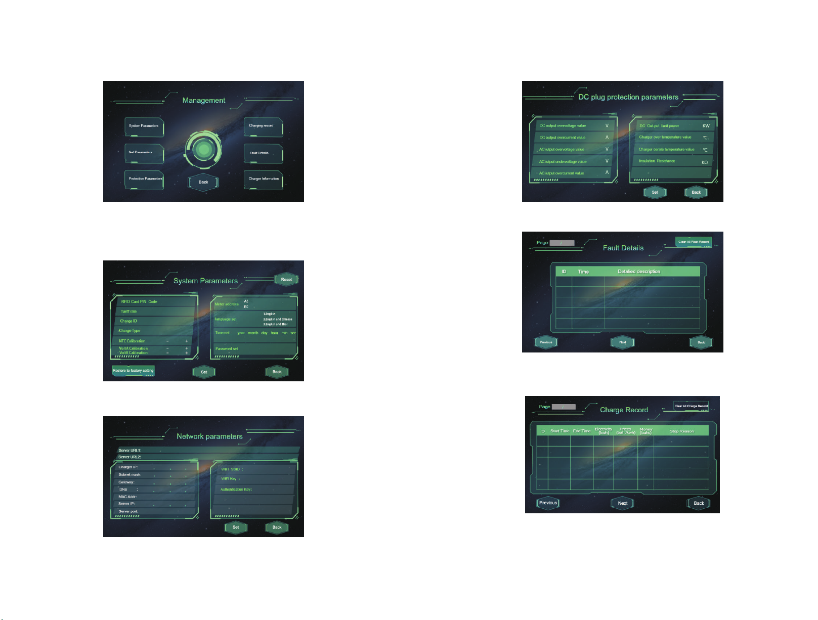
3.1.3 Click the menu button in the lower left corner to enter the pile setting interface.
10
9

3.1.4 System settings page
Fig3.1.3 Click input the menuinterface
Fig3.1.4.1 System parameter setting page
Fig3.1.4.2 Network parameter setting page
Fig 3.1.4.3 Protection parameter setting page
Fig 3.1.4.4 Fault information display page
Fig 3.1.4.5 Charger information display page
12
11

3.1.5 After charging is complete
1. If the charging mode is Plug&Charge mode, need to click the corresponding gun A or B to stop
charging.
2. If the charging mode is APP/RFID mode, need to click the corresponding gun A or B first, then swipe
the card to finish charging or complete the subsequent stop charging operation on the app.
If the screen shows the machine fault please do not charge, please contact the staff;
When credit card to confirm the balance of IC card sufficient, the lack of balance in the charging
process will automatically terminate the charge;
When two charging guns are used at the same time, the user should carefully identify whether
they are A users or B users and swipe the card according to the operation prompt of the interface to avoid
misoperation;
Please operate according to the charging equipment related instructions;
When plugging and unplugging the gun pay attention, must not be too hard;
During the card swiping operation, you need to hear "beep" beep to remove the card, otherwise it
may cause the operation to fail;
When charging gun plugged in EV and charger lit the yellow light, do not operate the charging
gun to prevent electric shock.
Press the emergency button in case of fault happening.
Check the SPD frequently. If the below observing window becomes red, the SPD is already broken
and needs replacing.
3.3 Operational precautions
During the process of using, dust should be regularly collected on the top, and the air inlet
air filter or air filter should be cleaned or replaced. During the process of replacing the air filter,
the product needs to be powered off.
Fig 3-1-1 AC SPD
Fig3-1-2 Dust net and ventilation diagram
1.inlet air flow 2. dust filter taken out direction
3.4 Indicator light description
There are three status lights above the device, yellow, green and red lights respectively.
Green: Is the power indicator, stead green light on the device after power on.
Yellow: Charging, yellow light on; charging stopped, yellow light off; yellow light flashing,
charging gun being connected.
Red: Equipment failure, red light; failure solved, red light off.
14
13

3.5 Emergency stop switch instructions
If a leakage occurs in the machine, immediately press the emergency stop switch.
If a fire or electric shock occurs, immediately press the emergency stop switch.
Charger failure, such as charging cannot stopped, internal circuit short circuit and other abnormal
conditions, please immediately press the emergency stop switch.
Press the emergency stop button at non-charging status, the fault light lit, the LCD jump to the
fault interface.
When the critical situation is lifted, please rotate the emergency stop switch, or it can not continue
to charge.
3.6 Common fault indications and solutions
No.
1
2
3
4
5
Fault display
Emergency button pressed
SPD failure
Input over/under voltage fault
Over-temperature protection
Output over-voltage over-current fault
Solution
Rotate the emergency button to release.
Check the SPD module and replace the
damaged SPD module.
Stop using it, wait for the grid voltage to
resume normal, and the charger
automatically resumes to release the
fault. Check the protection threshold
setting.
Check if the air inlet and outlet air filter is
blocked, maintain good ventilation and
cooling, charger temperature dropped to
the operating temperature range, it will
automatically remove the fault, revert to
the usable state.
Check the threshold setting if grid voltage
is normal.
Installation 4
4.1 Installation conditions
1) The surrounding of the charger body shall meet the operating space not less than 1.2 meters,
as shown below;
Fig 4.1.1 Installation space map
2) Charger must be installed on the basis of customized concrete, cement concrete foundation
installation diagram as shown;
Fig 4.1.2 Cement foundation map
16
15
600mm
500 m m
110 0mm
110 0mm
600mm

Description:
1. The foundation pit must be tamped. On loose and moist soil, the foundation must be reinforced. The
foundation must sit at the highest point of the area to avoid flooding water.
2. The foundation pile is to be made of reinforced concrete, which requires for a minimum allowable
bearing pressure of 1000kg/squire meters for the base.
3. Construct main grounding busbar and electrode following the grounding regulation of transformer
substation. Grounding resistance should be lower than 4Ω,50x4 galvanized flat steel is suggested.
4. Cable conduit uses PVG of 150mm diameter, the direction should be determined according to the
situation on site, while the quantity is according to how many HV/LV cables will be used(use redundant
design) .
5. Level bar should be used to level the foundation ground.
6. Internal foundation level should slightly lean towards water-collecting pit.
7. The figure is just for reference.
3) Installation basement must be above the ground level by at least 150mm, the vertical tilt of the
installation does not exceed 5%;
4.2 Charger installation
4.2.1 Transport of charger with entire packaging
Related matters needing attention
Note1: DC charger as a whole, regardless of transport or installation shall not be decomposed. The failure
caused by retrofitting not authorized by ATESS does not cover the warranty.
Note2: In the process of moving the DC charger can not tilt, fierce shaking or sudden force, such as a
sudden drop or lift.
Note3: Carefully read the parameters to select the appropriate transport and storage location.
Suggest that the user try to use forklift to move DC charger.
4.2.2 Transport of charger without packaging
4.2.2.1 Removing the DC charger Package Follow these steps to remove the
equipment shipping container
Step1:Remove the wooden side of the box and the roof;
Step2:Remove the peripheral packaging materials on the machine;
Step3:Remove the anchors on the machine and transport plate.
4.2.2.2 Movemenet installation of charger without packaging
The DC charger, which has been disassembled, can be moved by forklift, crane, slide or crane. If
the location of the unpacking location is a little further from the final installation, it can be
transported with the bottom wooden pallet, see the following figure:
Fig 4.2 .1 Movement of charger without packaging
Attention!
Before moving the DC pile cabinet to a predetermined position, it is
recommended that the AC mains cable be routed first. Because these cables are
thick, it is difficult to wire the cabinets once the DC pile cabinets are installed.
4.2.3 Installation basement requirements
1.According to drilling template requirements, drill four holes with a diameter of 18mm and a
depth of 100mm on the cement base. The distance between the four holes is shown in the
following figure. The expansion bolt is then inserted into the drilled hole through the wall
expansion.
2.Align the charger with the mounting holes and put it on the cement base, tight with M10X60,
M12X60 bolt;
3.Good and secure grounding connection between DC charger and cement basement, grounding
resistance lower than 4Ω.
Fig 4.2.3 Bottom mounting plan
18
17

4.3 Cable connection
Connect the three-phase cables embedded in the charger foundation to the input end of the charger, Pay
attention to the connection of five lines,Color correspondence, Connect the ground wire on the cabinet
to ground, as shown in the following figure. Note: For safety, all DC chargers need to be grounded
through PE conductors.The PE copper row in the DC charger cabinet has been reliably connected with the
shell of the DC charger in the cabinet, When PE connection, it is necessary to connect the PE grounding
busbar to the equipotential bonding device in the installation site reliably.Grounding cable diameter not
less than 50mm2, grounding resistance shall not exceed 4Ω.
4.3.1 Wiring
Fig 4.3.1 Input wiring diagram
Fig 4.3.2 Ground copper row
4.3.2 Cable requirements
Cable
L1
L2
L3
N
PE
COM
Diameter
At least 150mm²
At least 150mm²
At least 150mm²
At least 4mm²
At least 50mm²
At least0.75mm²
Mounting hole diameter
Φ11,M10 screws recommended for fastening
Φ9,M8 screws recommended for fastening
-
6
Packaging
transportation and storage
1) Packaging
Charger body tightened with wrapping film, surrounded by foam support, external wooden
packaging.
2) Transportation
The product should not be violent shocks, impact and inversion during transport, so as to avoid
damage to the product.
3) Storage
If the product needs to be stored after it is purchased, it must be placed in a dry, well-ventilated
indoor place, not upside down.
20
19
5.1 Safety check before use
Before using this product, please carefully check the following:
1. Make sure the product is not scratch, rust, deformation and so on.
2. Make sure the power outlet is secure and there is no sundries in the charging plug and the
vehicle's charging socket.
3. Please do not continue to use the charging cable or the charging gun if there is any damage to
the housing or bare cables.
4. Keep the charging gun plug dry, if there is water, please use a dry clean cloth to dry the
charging plug in the state of charger power off.
5
Parameter configuration

7.2 After-sales service
Under the conditions of customer obide by the requirement of custody, installation, use and operation,
within 12 months from the date of completion of the installation and passed the acceptance inspection.
Or if storage is needed, the product will be 12 months from the date of receipt of the customer, If the
product is down due to poor manufacturing quality or can not be used normally, the manufacturing part
has the responsibility to provide free repair, commissioning or replacement parts.
7.3 Attachment list
1) Supporting equipment such as the backup of some common devices, installation or operating tools,
etc. can be equipped according to customer needs.
2) Technical documents: "User Manual", certificate, warranty card, factory inspection report.
Appendix
Tab1: Technical standards and regulations
No.
1
2
3
Classification
Emission
Immunity
LVD
Standards
EN61000-6-3(2007)+A1(2011),class B
EN61000-6-2(2005)
EN60950-1:2006+A11:2009+A1:2010+A12:2011+A2:2013
EN61010-1:2010
EN60335-1:2012+HD60364-4-41(2007)Part4-41
EN61851(2011)
IEC92196-1(2003)
Appendix II Electrical Schematics
Appendix I Technical standards and regulations
22
21
7.1 Ordering note
Must understand the equipment applications and uses, fill out the customer needs table;
When ordering, provide product name, model, specifications, system parameters and
configuration requirements;
Users have special use of equipment or technical requirements, please consult with the factory
technical staff, signed an agreement.
7Ordering instructions and after-sales service

The EVD-300D DC charger products features with high efficiency, advanced DSP control
technology, perfect protection features, etc., to reliable operation, easy operation and easy
maintenance.We believe that this product will be more widely used in many commercial and civil
fields. To this end, we sincerely thank the majority of users and those concerned about the
product!
In order to further understand and use this product, the user's manual provides a detailed
introduction to the functions, installation, operation and maintenance of the EVD-300D DC
charger. This manual is indispensable when installing, debugging and maintaining the DC pile
data.
We sincerely hope that this product will meet your needs, and hope you can put forward more
comments on the performance and function of the product. We will continue to improve and
continuously improve product quality.
23
Table of contents
Other ATESS Batteries Charger manuals