Tractor Preparation
©2018 Dawn Equipment Company, Inc. 370 N Cross Sycamore, IL 60178 USA www.dawnequipment.com Toll Free: 800.554.0007 Fax:815.899.3663
TRACTOR TIRES (6.1)
In general, set the tractor tires (center to center) at 4x
the row spacing (exe. 120” center to center for 30” row
spacing). The minimum row spacing for the Pluribus
Unit is 22”. Make certain that the tires are inflated to
the recommended pressure for your conditions.
The majority of Pluribus Strip-Till users run on 30”
centers, and split the previous years rows. This
typically places the tractor tires running over stalks.
You may want to consider an aftermarket tool
designed to flatten the stalks and reduce tire wear. If
you are equipped with high precision guidance, you
may also consider running at an angle to the previous
years rows. The practice of running at an angle can
also have additional performance benefits in some
conditions.
LIFT CAPACITY (6.2)
Due to the low horse power requirements of the
Pluribus unit, many users will opt for a smaller tractor
to pull the implement. One important factor to
consider, however, is the lift capacity of the tractor
hitch. Each Pluribus unit can weigh in excess of 700
lbs.. If you will be using a mounted toolbar, please
ensure that your tractor is capable of easily lifting the
combined weight of the toolbar, the strip-till units and
any additional fertilizer distribution equipment. Should
your lift capacity be adequate, there is still a potential
that you are excessively tail heavy. If you have
difficulty steering in the transport position, you may
have to add weight to the nose of the tractor.
WARNING!: Driving uphill with a tail heavy tractor is
dangerous! Tractors with excessive tail weight are
susceptible to rollovers.
(Note: The procedure for determining lift capacity on a
tractor equipped with a 3-point hitch can be found in ASAE
S349.2)
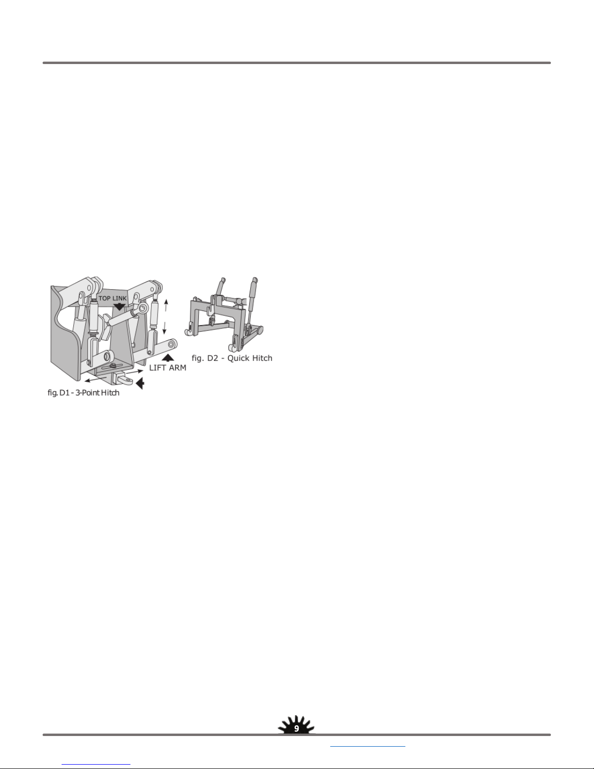
THREE POINT HITCH (6.3)
If you have a mounted tool bar, you will want to ready
your 3-Point hitch. Hitches that have seen little use
can freeze up. It is recommended that your free up all
your links in preparation for toolbar leveling
adjustments. Additionally, it is recommended that you
install an aftermarket hydraulic upper link so that you
can quickly adjust the toolbar pitch as field conditions
change.
TRACTOR DRAWBAR (6.4)
The industry standard for tractor drawbars is
approximately 17.5” above ground level. Not all
manufacturers adhere to this standard, nonetheless it
is very important that the toolbar be hitched in such a
way that it can be easily leveled fore and aft. If you
are unable to connect your toolbar in such a way that
it can be easily leveled, please contact Dawn for
advice on your particular tractor/toolbar configuration.
Make sure the drawbar has eyelets for safety chains.
Pulling an agricultural implement without safety chains
is dangerous!
TRACTOR HYDRAULIC SYSTEM (6.5)
Understanding your tractor hydraulic system is
critically important, and you should thoroughly
familiarize yourself with the hydraulic system
instructions provided by the tractor’s manufacturer.
HYDRAULIC PRESSURE (6.5.a)
Know the maximum operating pressure of each
hydraulic component. Exceeding the recommended
pressure can result in equipment damage or failure.
Pressure recommendations can be found in the users
manual of most agricultural implements. Also ensure
that there is adequate pressure, should you have a
system that employs multiple hydraulically driven
components.
HYDRAULIC VALVES / COUPLERS (6.5.b)
Hydraulic cylinders are susceptible to abrasion due to
impurities in the hydraulic fluid. It is recommended
that you use a clean cloth to remove any abrasive
particulate that may have collected in and around the
valve plug, and the connecting socket. Always keep
dust covers in place when valve is not in use. Test
your hydraulic hoses and couplers. Make sure there
are no leaks.
WARNING!:
Hydraulic fluid under pressure is
dangerous! Small holes in hydraulic lines may eject
streams of fluid at high pressure. Hydraulic fluid that
penetrates the skin can cause serious infection that can
lead to amputation. Should oil penetrate your skin, even
if it is relatively painless, seek immediate medical
attention.