Dawson HPH 1200 User manual

www.dcpuk.com
INNOVATIVE
PILING
EQUIPMENT
HYDRAULIC PILING HAMMERS
EXCAVATOR MOUNTED
VIBRATORS
EXCAVATOR MOUNTED DRILLS
QUIET, VIBRATIONLESS
PUSH-PULL PILING
PILE EXTRACTION
SHEET PILE GUIDE FRAMES
SHEET PILE
CAPPING SYSTEMS
CFA CLEANERS
PILE POINTS
& SPLICERS
HANDLING / LIFTING
www.dcpuk.com
HPH 1200
HYDRAULIC HAMMER

DAWSON
CONSTRUCTION PLANT LIMITED
HPH 1200 HYDRAULIC
HAMMER AND POWER PACK
- USER'S MANUAL
HAMMER SERIAL NO: ..............................................
HAMMER COMMISSION DATE: .............................
POWER PACK SERIAL NO: ......................................
POWER PACK COMMISSION DATE: ......................
ENGINE TYPE: ...........................................................
ENGINE SERIAL NO: ................................................
POWER PACK TYPE: .................................................
V8 05/06/06

C O N T E N T S
0.0 EC Declaration of Conformity
1.0 Introduction
1.1 Basic Safety Points
- Basic Specification of HPH 1200 - Drawing
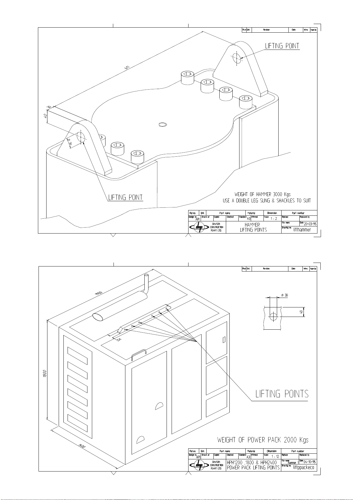
- Lifting the HPH 1200 & Power Pack -
Drawing
1.2 Transportation and laying hammer down
2.0 How does the Hammer Work?
Figure 1
3.0 Power Pack and Hammer Operation
3.1 Connecting the hydraulic hoses and
control pendant
3.2 Checking the power pack
3.3 Starting the power pack
3.3.1 Hydraulic oil warm-up procedure
3.4 Using the hammer
3.4.1 Installing hammer on the pile
3.4.2 Bleeding air from the hammer
hydraulic system
3.4.3 Pile driving with the hammer
3.4.4 Cold running/overtravel
3.4.5 Refusal
Figure 2
3.5 Using the hammer underwater
3.6 Wider or special pile sections
Figure 3
Figure 4
3.7 Preventive Maintenance Guideline Chart
4.0 Hammer Maintenance
4.1 Daily maintenance
4.2 Planned 125 hour maintenance checks
4.3 Planned 250 hour maintenance checks
4.4 Planned 500 hour maintenance checks
4.4.1 Changing Resilient Washers
4.4.2 Other items
Figure 5
4.5 Planned 1000 hour maintenance checks
5.0 Power Pack Maintenance
5.1 Power pack specifications
5.1.1 Basic specification
5.1.2 Lubrication specification
5.2 Daily maintenance checks
Figure 6 Dolly wear
5.3 Planned maintenance checks
5.3.1 Every 125 hours
5.3.2 Every 250 hours
5.3.3 Every 500 hours
5.3.4 Every 1000 hours
5.4 Maintenance procedures
5.5 Setting procedures
6.0 Troubleshooting
6.1 Power pack engine will not start
6.2 Engine cuts out during running
6.3 Power pack does not generate any pressure
6.4 Power pack generates pressure but hammer
does not run
6.5 Hammer will lift but not drop
6.6 Hammer runs erratically
6.7 Excessive hose 'jumping'
6.8 Hammer 'jumping' excessively on pile top
6.9 Stroke height indicator will not move
6.10 Smoke from bottom end of hammer
7.0 Appendices
7.1 Hammer parts list
7.2 Accumulator parts list and instructions
7.3 See Cummins service manual
7.4 Power pack parts list
7.4.1 Hydraulic circuit schematic
7.4.2 Electrical circuit schematic
7.4.3 General assembly drawing - 3 off
7.5 Tool kit parts list

Description:
1. Hydraulic Piling Hammer
2. Power Pack - 93kW
Type:
1. Hyd Piling Hammer - HPH 1200
2. Power Pack - 1800/2400 Diesel Engine
Hydraulic
Serial Number:
1. HPH1200 –
2. Power Pack -
DAWSON
The responsible person:-
DAWSON CONSTRUCTION PLANT LIMITED
CHESNEY WOLD, BLEAK HALL
MILTON KEYNES MK6 1NE
ENGLAND
EC DECLARATION OF CONFORMITY
The above mentioned equipment conforms to the Machinery Directive 89/392/EEC(a)
as amended by Council Directive 91/368/EEC(b), Council Directive 93/44/EEC(c)
and Article 6 of Council Directive 93/68/EEC(d).
Signed for and on behalf of
Dawson Construction Plant Limited: .............................................................................
Name: .............................................................................
Position: .............................................................................
Date: ............./............./.............

1.0 INTRODUCTION
The D.C.P. Hydraulic Hammer has been designed and manufactured to meet the demands of today's
contractor. The hammer has many advantages over traditional piling hammers, including other
hydraulic hammers:-
- The hammer fits all British and most foreign single sheet piles as well as numerous 'H' piles using
one set of legs and inserts. It will also fit pairs of sheet piles and open bent corners with the same
configuration. This significantly improves productivity and reduces costs.
- The hammer does not have a single electrical component on it. This means no vulnerable
electrical cable running across the site and no delicate electronics on the hammer. All competent
fitters can understand this hammer.
- Hydraulic hammers are inherently efficient, typically 80-90% of the potential driving energy
being transferred into the pile as opposed to 25-35% for diesel hammers.
- Rapid blow rate. The hammer is double acting, not only giving high energy output, but
increasing the speed of operation. This inevitably increases production and keeps the pile on the
move.
- Infinitely variable stroke controlled, between limits, at the touch of a button. This enables precise
energy control which is very important when commencing piling or when coping with delicate
operations.
- Robust construction. The hammer has been designed with full knowledge of what is required of
piling equipment. A quick look at the hammer sitting on a pile will confirm this.
- With the hammer weighing only 3 tonnes, it lends itself to being used on long reach jobs where
there are few economic alternatives.
- Noise levels are considerably lower than that of diesel or air hammers.
- Transmitted ground vibrations have been measured lower than that of a vibrator.
1.1 Basic Safety Points
- Ear protection should be worn when in close proximity of the hammer.
- Keep clear of the hammer and/or power pack when they are being lifted.
- Avoid standing directly below the hammer when it is piling.
- Adhere to maintenance requirements set out in this manual.
- Lift equipment using lifting points specified only (see figures over).
1.2 Transportation and laying down hammer
- BEFORE operating hammer first time AND after each lay-down use inspection holes to ensure
dolly is seated correctly in anvil before striking.
- WHEN LAYING DOWN HAMMER, support top of hammer at higher level than bottom of
hammer.
- TRANSPORTATION, support top of hammer at higher level than bottom of hammer.


2.0 HOW DOES THE HAMMER WORK? (See fig. 1)
The D.C.P. Hydraulic Hammer consists of a 'drop weight' driven up and down by a 'hydraulic ram'
inside a 'casing.' The hydraulic ram is double acting which means the drop weight is accelerated
both on the upstroke and on the downstroke. This gives the hammer its very efficient energy output
and high blow rate.
The oil supplied to the hydraulic ram comes from the power pack via a 'control valve' mounted
inside the top of the hammer. This control valve switches the oil supply on or off at the upstroke
side of the hydraulic ram i.e. oil supply 'on' lifts the drop weight and oil supply 'off' drops it.
The control valve itself has to be switched from one position to another at precisely the right times
for optimum performance. The control valve is switched by hydraulic pilot signals from two
mechanically actuated sensors mounted on the hammer casing. The 'bottom sensor,' when actuated
by the drop weight, switches the control valve to the on (lift) position and the 'top sensor' switches
the control valve to the off (drop) position. The stroke of the drop weight is adjusted by moving the
position of the top sensor e.g. moving the sensor down reduces the stroke or vice versa.
The position of the top sensor is altered by a small 'height adjusting ram' mounted inside the top of
the hammer. This is adjusted as required by the operator who can view an indicator on the side of
the hammer.
The hammer is fully controlled using a hand-held control pendant. This unit enables the hammer to
be started/stopped, run on single/automatic blows and have its stroke varied. The controller may be
used from a remote position.


3.0 POWER PACK AND HAMMER OPERATION
3.1 Connecting the hydraulic hoses and control pendant
(The power pack must be turned off at this time to enable correct installation of the hoses)
There are four hydraulic hoses running between the power pack and the hammer, viz:
1. Pressure line (1" BSP) carries the main high pressure oil supply to the hammer.
2. Return line (1¼" BSP) returns low pressure oil from the hammer to the power
pack.
3.} Height adjusting lines (3/8" BSP) used to deliver
4.} Oil to the height adjusting ram, as required.
The pressure/return hoses have the same specification. However, the return hose ends have larger
fittings than the pressure hose to avoid possible confusion. Similarly, the height adjusting hoses
have different end types. The hoses should be left connected to the hammer at all times - this
reduces the likelihood of oil contamination and reduces leakage problems. The hoses should be
connected/ disconnected at the outlets of the power pack. All these connectors are of the
'quick-release' type. The hoses should be disconnected from the power pack when moving the
power pack around to avoid straining the connectors.
Make sure that the connectors are thoroughly cleaned when making a connection
Having connected the hoses, next fit the hand control pendant connector block to the multi-pin
outlet from the power pack. This is positioned below the instrumentation panel of the unit. Check
that a clean connection is made and that no water is present in either half of the connection. The
'power' switch on the controller should be turned off.
3.2 Checking the power pack before starting
Having connected the hydraulic hoses and hand control pendant, as described in section 3.1, next
check fluid levels on the power pack. Check:
a. engine oil level
b. diesel fuel level
c. hydraulic oil level, and fill if required
Notes:-
1. The diesel fuel and hydraulic oil tanks have sight gauges on the side of the tanks.
2. The power pack will not run if the hydraulic oil level is too low.
3. The hammer will not run if the hydraulic oil temperature is too low. The auto warm-up routine
must be used to pre-warm the oil. See section 3.3.1.

3.3 Starting the power pack (see fig. 2)
Prior to starting the power pack, check that the hand control pendant is turned 'off.' Set the throttle
control lever to half of full throttle (2). Turn 'on' the battery isolator (1). Push the engine start push
button (4) until the engine starts.
Allow the engine to reach working temperature by running it at 1500 r.p.m. under zero load for
10-15 minutes. Check all gauges and diagnostic lights for correct function of unit (diagnostic lights
should be off.)
Notes:-
1. If any of the following L.E.D.'s (7, 8, 9 or 10) are 'on' when the isolator switch (1) is turned 'on,'
the power pack will not start. Rectify problem immediately.
2. If L.E.D. (12) is on, the power pack will start but the pendant will be ‘dead’ until the hydraulic
oil warm up procedure is carried out.
3.3.1 Hydraulic Oil Warm-up Procedure
If the hydraulic oil temperature is less than +25ºC, L.E.D. (12) will be on and the oil will require
warming prior to using the hammer.
The hand control pendant will be ‘dead’ for as long as L.E.D. (12) is on.
To warm the oil:-
a) Run the engine at 1800 r.p.m.
b) Turn the ‘warm-up/run’ selector switch (13) to ‘warm-up’. (The engine should go under load
and the high pressure gauge (5) should read approx. 200 bar).
c) Leave the pack in this condition until the L.E.D. (12) goes off. (The engine should come off
load at the same time the L.E.D. goes out and gauge (5) return to zero bar).
d) Turn the ‘warm-up/run’ selector switch (13) to ‘run’. The power pack is now ready for use.
3.4 Using the hammer
3.4.1 Installing hammer on the pile
The hammer must be sat correctly on the pile to avoid hammer or pile damage. The pile tops should
be as level and square cut as possible. The hammer anvil must be in good condition.
Lift the hammer onto the pile(s) to be driven. Lower the hammer down until the handling slings
lose their tension. At this point, the anvil should be seated correctly i.e. the rubber ring around the
anvil should be compressed between the casing and the anvil. If it is not and there is a gap here,
re-site the hammer.
Note: Before using the hammer (and particularly after transportation) check
that the dolly is fitted correctly in the anvil.

3.4.2. Bleeding air from the hammer hydraulic system - only required
when running hammer after initial connection or following a repair
When running the hammer for the first time after initial connection to the power pack, there will be
air in the hydraulic system. The hammer will 'bleed' this air automatically but the following
procedure must be applied:-
a. Run the power pack at 2300 r.p.m.
b. Turn on the control pendant 'power' button.
c. Adjust the stroke height indicator to minimum using the '↓' push button.
d. Set the 'Auto/Man' turn button to 'Man.'
e. Hold the 'start' push button down for 2-3 seconds.
f. Repeat (e) three or four times until the hammer consistently gives one or two small blows each
time. Providing the hammer does not 'jump' on the pile, hold the 'start' push button down, so
that the hammer gives several consistent blows, on the next operation. (Approximately 120
blows per minute.) If the hammer 'jumps' on the pile, because the drop weight is hitting the top
of the hammer casing, the hammer will stop automatically. To reset see section 3.4.4.
g. Commence the piling operation using the hammer as required.
3.4.3 Pile driving with the hammer
Having the hammer sited on the pile and removed air from the hydraulic system (if necessary) as
described above, the hammer is ready for pile driving:-
a. Increase the power pack engine speed to 2300 r.p.m. (having followed - "Starting the power
pack" section 3.3)
b. Turn the hand control pendant 'power' button on.
c. Adjust the 'stroke height indicator' on the side of the hammer to minimum stroke by pressing the
'↓' push button.
d. Set the 'Auto/Man' selector button to the required position:
'Auto' - hammer will continue running automatically when the 'start' push button is pressed once.
'Man' - hammer will only run whilst the 'start' push button is held down.
e. Depress the 'start' push button as required by 'Auto/Man.'
f. During operation the hammer stroke may be altered using the '↑' or '↓' push buttons to adjust the
stroke height indicator.
g. To stop the hammer whilst it is running on 'Auto,' turn the 'Auto/Man' selector to 'Man' or turn
the 'power' selector off.

It is good practice to start piling with the hammer set on minimum stroke, this limits unnecessary
damage to both the hammer and the pile when the pile can be driven easily. The stroke may then be
adjusted to suit the changing driving resistance.
On certain piling jobs, it may be possible to start driving on pairs of sheet piles, changing over onto
a single sheet pile as the driving resistance increases (this will give maximum productivity.)
3.4.4 Cold running/overtravel
The hammer 'jumps' on the pile top when trying to achieve full stroke if the hydraulic system is
'cold.' If this happens, the hammer will stop automatically. (Thus preventing internal damage to
the unit.) The power pack will continue to run and the 'pressure' gauge will read approximately 240
bar.
In order to reset the hammer, turn off the 'power' selector on the hand control pendant and stop the
power pack. Allow the engine to stop for approximately 10 seconds then restart the unit. Reduce
the stroke of the hammer to minimum. Run the hammer at this lower setting until the oil is warm
enough to allow correct full stroke setting. If reducing the stroke does not cure the problem, warm
the hydraulic oil as described in section 3.3.1.
If the hammer overtravels again, refer to the Troubleshooting section 6.0.
THE HAMMER WILL NOT RUN IF IT IS NOT ALLOWED TO RESET CORRECTLY
3.4.5 Refusal
Piling must stop with this hammer when the rate of driving reaches 10 blows per 25mm.
Continued use will result in hammer and/or pile damage


3.5 Using the hammer underwater
It is possible to drive piles with this hammer underwater. However, the hammer must be prepared
correctly in order to do so - it can not be used underwater in standard format.
The work involved is briefly as follows:-
a) The stroke adjuster ‘slot’ in the leg guide must be sealed with a cover.
b) The insides of the hammer should be suitably greased to minimise the effects of corrosion.
c) The gaps between hammer casing, leg guides and top cover must be sealed with silicone mastic.
d) The inspection holes near the bottom of the hammer casing must be plugged.
e) A threaded compressed airline port must be added in the bottom end of the hammer casing or leg
guide.
f) The hammer must be run in conjunction with a 35/70 c.f.m. (100 psi) air compressor.
g) The hammer grease nipples must be greased after every pile drive to ensure ample lubrication.
NOTE: FOR DETAILED ASSISTANCE WITH THIS TYPE OF WORK PLEASE CONTACT
THE MANUFACTURER.
3.6 Wider or special pile sections.
The HPH 1200 hammer in standard format will drive a considerable range of steel piles. In some
applications, however, where sheet piles are particularly wide or perhaps boxed together it is
possible to use simple leg insert modifications and/or spreader plates to give improved pile coverage
reducing pile head stress and improving productivity rates.
A good example of this is with B.S.C. LX or Arbed PU type sheet piles. The standard leg inserts
can have “wing extensions” bolted on to correctly centralise the hammer on a single sheet pile.
Then either a special anvil can be used to give wider coverage, or, by dropping the inserts to a lower
set of location holes, a ‘spreader plate’ can be added below the standard anvil to give improved pile
coverage. This is a tried and tested technique (see figure 3).
With tubular piles, for example, the standard inserts can be removed and in place some simple bolt
on plates added to centralise the hammer on the tube (see figure 4). A further refinement, if
necessary, is to weld a ring onto the underside of the anvil to give correct location on the tube.
PLEASE CONTACT THE MANUFACTURER IF YOU HAVE A SPECIFIC PILE DRIVING
PROBLEM - IT MAY HAVE BEEN DONE BEFORE!


3.7 PREVENTATIVE MAINTENANCE GUIDELINES FOR HPH 1200 & 2400 HYDRAULIC HAMMERS, AND DIESEL ENGINED POWER PACKS
DAILY OR REFUELLING EVERY 125 HOURS EVERY 250 HOURS EVERY 500 HOURS EVERY 1000 HOURS EVERY 2000 HOURS
CHECK
:
•
OIL LEVEL
•
COOLANT LEVEL
•
FAN
-
INSPECTION
•
DRIVE BELT
-
INSPECT
•
FUEL WATER TRAP
-
DRAIN
CHANGE
:
•
LUBE OIL
•
LUBE FILTER
CHECK
:
•
AIR CLEANER
•
INTAKE SYSTEM
•
CHARGE AIR COOLER
CHANGE
:
•
FUEL FILTER
CHECK
:
•
ANTI FREEZE
ADJUST
:
•
VALVE LASH CLEARANCE
CHECK
:
•
FAN HUB
•
BELT TENSIONER BEARING
•
BELT TENSION
CHANGE
:
•
ANTI FREEZE
CHECK
:
•
DAMPER
CHECK
:
•
HYDRAULIC OIL LEVEL
•
AIR INLET
/
OUTLETS FREE
FROM OBSTRUCTION
•
CONDITION OF LIFTING POINTS
&
SLINGS
/
SHACKLES
•
TEST DIAGNOSTIC LEDS
•
INSPECT GAUGES
•
CONDITION OF QUICK RELEASE
COUPLINGS
CHECK
:
•
FOR HYDRAULIC OIL LEAKS
&
RECTIFY
•
CONDITION OF HOSES
•
TIGHTNESS OF FASTENERS
•
CONDITION OF PAINTWORK
•
BATTERY WATER LEVEL
•
FUNCTION OF PENDANT
&
CONDITION OF CABLE
CHECK
:
•
BATTERY CHARGING
CHANGE
:
•
HYDRAULIC OIL
/
FUEL
FILLER FILTERS
CHECK
:
•
PRESSURE OUTPUT OF PUMP
•
FLOW OUTPUT OF PUMP
CHANGE
:
•
PRESSURE
/
RETURN
HYDRAULIC FILTERS
CHECK
:
•
CONDITION OF WIRING
•
DRIVE COUPLING FOR WEAR
•
CONDITION OF EXHAUST
CHANGE
:
•
HYDRAULIC OIL AND CLEAN
OUT SYSTEM
CHECK
•
ALL EXTERNAL FASTENERS
FOR TIGHTNESS
•
DOLLY CONDITION
•
SUSPENSION BLOCK
&
SUSPENSION RING CONDITION
•
LIFTING POINT CONDITION
•
SERVICEABILITY OF
SLINGS
/
SHACKLES
MUST
:
•
GREASE HAMMER
FREQUENTLY
CHECK
:
•
TIGHTNESS OF ALL HOSES
,
FITTINGS AND FASTENERS
INSIDE HAMMER
•
CONDITION OF BOTH
SENSORS
•
WEAR LEVEL ON LEG INSERTS
CHECK
:
•
ACCUMULATOR NITROGEN
PRECHARGE PRESSURES
•
HAMMER FILTER
•
FUNCTION OF OVERTRAVEL
VALVE
•
FUNCTION
/
CONDITION OF
PROBE ASSEMBLY AND
BOTTOM TRIP DEVICE
CHANGE
:
•
RESILIENT WASHERS
BETWEEN DROP WEIGHT
&
HYDRAULIC RAM ON HPH
2400
ONLY
CHECK
:
•
CONDITION OF HEIGHT
ADJUSTING RAM
•
TIGHTNESS OF
ACCUMULATORS
•
CONDITION OF MAIN FEED
HOSES TO HAMMER
CHANGE
:
•
RESILIENT WASHERS BETWEEN
DROP WEIGHT AND
HYDRAULIC RAM
CHECK
:
•
PLAY IN MAIN RAM
ANCHORAGE ASSEMBLY
•
CONDITION OF ANVIL
•
PLAY BETWEEN DROP WEIGHT
AND CASING BORE
-
TEST RUN ON PILE
15
MINUTES
BEFORE AND AFTER CHECKING
TEST RUN ON PILE
15
MINUTES
BEFORE AND AFTER CHECKING
TEST RUN ON PILE
30
INUTES
BEFORE AND AFTER CHECKING
TEST RUN ON PILE
30
MINUTES
BEFORE AND AFTER CHECKING
TEST RUN ON PILE
30
MINUTES
BEFORE AND AFTER CHECKING
(FOR FULL DETAILS SEE SECTIONS 4 AND 5 IN THE HAMMER MANUAL AND THE CUMMINS SERVICE MANUAL)

4.0 HAMMER MAINTENANCE (SEE APPENDIX 7.1)
4.1 Daily maintenance checks (or every 10 hours)
a. Apply Lithium based general purpose grease to hammer through each one of five grease points
(part 1-057-00-01). Ten operations of a grease gun on each grease point every shift will be
adequate. If the hammer is working particularly hard grease more frequently.
b. Check all external fasteners for tightness and re-tighten where necessary.
c. Check that the dolly (part 1-006-00-06) has not been damaged or worn beyond its
serviceable limit. If the dolly is replaced, ensure that the O' ring is replaced with it (part
1-067-00-01.)
To inspect the dolly, remove eight screws (part 1-034-00-01) and drop the leg inserts
(1-019-00-01 and 1-020-00-01) down far enough to view the dolly. If the dolly is compressed
past it's serviceable limit i.e. 30mm of wear, or if the dolly is cracked or melted replace it.
To replace the dolly insert a steel bar through one of the holes in the bottom of the anvil (part
1-005-00-01) and drive the old dolly out using a hammer. Insert a new dolly (complete with O'
ring) ensuring that it is pushed fully home.
d. Check the suspension blocks (part 1-025-00-01) and suspension ring (part 1-024-00-05) for
wear/damage and replace if necessary. These must be in good condition at all times. These
items act as the hammers 'suspension system' reducing the shock transmitted from the blow to
the hammer and its components - very important for keeping the hammer functioning correctly.
e. Check the condition of lifting tackle and lifting points prior to being taken into service.
4.2 Planned 125 hour maintenance checks (run the hammer for 15 minutes before and after
this maintenance work)
Every 125 hours the following work should be carried out in addition to that described in 4.1
above:-
a. Remove each hammer leg guide in turn and check the condition and tightness of: all hydraulic
hoses and fittings; bolts; locking rings, and visually check all components for condition.
b. Check the condition of each sensor assembly paying particular attention to cam wear, roller
operated valve travel and tightness of fixing bolts. Each roller valve should have a travel of
4mm through full actuation of its associated cam. This measurement is critical and if it is not
achieved the hammer will not run correctly (as with the ignition timing on a motor car). Travel
can be lost through excessive cam wear or with wear on the roller or roller pin at the end of the
valve.
c. Check the condition of leg inserts to ensure correct fitting on pile sections. The inner faces of
each insert should touch the opposite insert. If not, the wear faces may require building up with
hard facing.

4.3 Planned 250 hour maintenance checks (run the hammer for 15 minutes before and after
this maintenance work)
Every 250 hours the following work should be carried out in addition to the work described in 4.1
and 4.2 above:
a. Check the accumulator (part 1-048-00-04) precharge pressures using the gas pressure checking
kit and a bottle of nitrogen gas. The high pressure accumulator is situated on the side of the
hammer that the supply hoses come in.
The precharge pressures are:-
High pressure -100 bar
Low pressure - 3 bar
To gain access to the accumulators it is necessary to remove the top cover (part 1-017-00-02.)
To check the precharge pressures see appendix 7.2 in this manual.
b. Check the hammer filter (part 1-079-00-02) for cleanliness. First remove the top cover (part
1-017-00-02.) Then unscrew the filter bowl and remove the filter element. Check the filter for
damage and any unusual debris. Wash the filter with clean diesel and blast through from inside
the filter with compressed air. Alternatively throw the element away if it is a non-metallic filter.
PAY EXTRA CARE NOT TO ALLOW DIRT INTO THE FILTER ASSEMBLY ON
RE-FITTING
c. Check the function and condition of the bottom trip device.
d. Check the function of the hammer’s overtravel valve by intentionally overstroking the hammer
when cold.
4.4 Planned 500 hour maintenance checks (run the hammer for 30 minutes before and after
this maintenance work)
Besides work mentioned in 4.1, 4.2 and 4.3 above the following work should be carried out:-
4.4.1 Change the Resilient Washers
The flexible coupling between the main hydraulic ram and the drop weight must be changed. The
procedure is quite straightforward (see figure 5). Failure to do this will result in an expensive repair.
a. Lay the hammer on stable level ground on its Front Leg Guide packed on timbers. Remove the
Rear Leg Guide (part 1-002-00-02).
b. Remove the 3 no. Nyloc Nuts, Dog Point Grub Screws and Anti-Vibration Washers (parts
1-334-00-01, 1-349-00-01 and 2-089-00-01) from the Connector Nut (part 1-011-00-02). It may
require a little heat to melt the Loctite on the grub screws.
c. Unscrew the Connector Nut from the Ram Connector (part 1-009-00-02) and remove the Nut
together with 2 no. Buffer Spacers (part 1-012-00-02) and the Resilient Washer 2 (part
1-016-00-02).
Table of contents
Other Dawson Power Tools manuals
Popular Power Tools manuals by other brands

Hougen-Ogura
Hougen-Ogura PUNCH PRO 75002A Operator's manual

Portek
Portek ULTRA Mk2 instruction manual

Hitachi
Hitachi WH14DBDL Handing instructions

Hazet
Hazet 9021 SR-1 operating instructions

Avery Dennison
Avery Dennison Fabric System 500 Operating and safety instructions

InkJetBiz
InkJetBiz XPress 1620SA user manual