DCA Intertel 2000 User manual
DCA Intertel 1 DCA Intertel
Technical
Manual
Mobile Printer 2000
DCA Intertel BV
Distributieweg 25, 2404 CM Alphen a/d Rijn
The Nederlands
Phone: +31(0)172 604963 Fax: +31(0)172 605237
website: www.dca-group.com

2DCA Intertel DCA Intertel
DCA Intertel 3 DCA Intertel
Table of Contens
1. DESCRIPTION 4
1.1 Printer Overview 4
1.1.1 Control Panel 5
1.1.2 Push Buttons 5
1.1.3 Signal Lights 5
1.2 Connectors 7
1.3 Sensor - Paper End 8
1.4 Sensor - Automatic Form/Paper loading and advance 9
2. INSTALLATION 11
2.1 Unpacking 11
2.2 Procedure for Installation 11
2.3 CAUTION! 11
2.4 Power Supply 12
2.5 Printer Set up 13
2.6 Paper Loading 14
2.7 Inked Ribbon Cartridge Installation and Replacement 15
2.8 Self Test 15
3.0 INTERFACES 16
3.1 TTL Interface 16
3.2 RS 232- Serial Interface 17
3.3 Parallel Interface 18
4. PRINTER FUNCTION 19
4.1 Printing Formats 19
4.2 Control characters 19
4.2.1 RESET (OPERATING COMMANDS.) 20
4.2.2 Aligment Tuning 20
4.2.3 Print direction and speed 20
4.2.4 Page Control 21
4.2.5 SENSORS 22
4.2.6 PRINTER STATUS 22
4.2.7 BUZZER CONTROL 23
4.2.8 DATA CONTROL 24
4.2.9 PAPER FEED 25
4.2.10 VERTICAL MARGINS (FORMAT COMMANDS) 27
4.2.11 VERTICAL TABS 27
4.2.12 HORIZONTAL MARGINS 29
4.2.13 HORIZONTAL TABS 30
4.2.14 TEXT JUSTIFICATION CONTROLS 31
4.2.15 PRINT QUALITY 31
4.2.16 PRINT PITCH (PRINTING STYLES) 32
4.2.17 CHARACTER WIDTH 33
4.2.18 PRINT STYLES 34
4.2.19 NATIONAL CHARACTER SET 36
4.2.20 POWER REDUCTION COMMANDS / select number of copies 36

2DCA Intertel DCA Intertel
DCA Intertel 3 DCA Intertel
4.3 CHARACTER SET 37
4.3.1 Control characters printing (German characters) 37
4.4 GRAPHIC CAPABILITIES 38
4.4.1 Graphics control characters 38
5. TECHNICAL INFORMATION MP 2000 41
5.1 Technical Specications 41
5.2 Printing Specications 42
5.3 Paper 42
5.4 Inked Ribbon Cartridge 43
5.5 Interfaces 43
5.6 Sensors 43
5.7 Power Supply 43
5.8 Environmental Limits 43
5.9 Dimensions and Weight 44
6. MAINTENANCE 44
6.1 Care and Cleaning 44
7. WARRANTY 44
8. SPAREPARTS BY ARTICLE NUMBER 45

4DCA Intertel DCA Intertel
DCA Intertel 5 DCA Intertel
1. DESCRIPTION
1.1 Printer Overview
Product Outline
MP 2000 is an impact dot matrix printer with tractor and friction feed mechanism for
use in mobile environments.
The mechanism is equipped with a ballistic nine needle printing head, it is able to print
at 150 cps in draft mode and 25 cps in NLQ (Near Letter Quality) mode on multi-copy
paper (one original and up to four copies).
Due to its compact size and reduced weight (2.2 kg), the MP 2000 is particularly sui-
ted for portable applications.
Power requirements have been kept to a minimum by means of two DC motors with
integrated optical encoders. Using an integrated driver board, this ensures the same
precision positioning in comparison to stepping motors.
The MP 2000 can print in the graphics mode along with different character fonts, both
in draft and NLQ mode. It has also been developed mainly for portable applications,
e.g. when connected to a lap-top.
MP 2000 comes standard with 2 Kbytes input buffer and comes with the following
choices of interfaces:
- TTL - level serial interface
- RS-232 serial interface
- Parallel interface
- IRDA infra red
The interface exibility ensures that the MP 2000 can work with almost any computer
system. The MP 2000 is software driven. It is compatible with the driver software of
EPSON LX 400 / LX800 and comes with his own windows ’95 and NT drivers.
Servermotor
Dip Switches
TTL Serial Interface
Control Panel
Optional Board
PRINTER HEAD
Power Supply
Power Board
Logic Board
HOT
Servermotor

4DCA Intertel DCA Intertel
DCA Intertel 5 DCA Intertel
1.1.1 Control Panel
The control panel is connected to the printer. It is tted with four push buttons and
three LED’s.
1.1.2 Push Buttons
On line / Off line
This push button switches the printer on and off line. When the printer is “ON LINE”, it
is ready to accept data from the computer.
Likewise when it is switched “OFF LINE”, the carriage automatically moves to the cen-
ter of the print span. When “ON LINE” the printer ignores the remaining push-buttons
(FF, LF, BF).
Form Feed
Paper advances by one sheet length (i.e. to the beginning of next page).
Line Feed
Paper advances by one line.
Back Feed
Paper retracts by one line.
When MP 2000 is “OFF LINE”, the combined activation of the “ON LINE” and “FORM
FEED” push-buttons causes the printer to go “ON LINE”. It assumes then the actual
paper position as “beginning of page”. Three beeps are generated to acknowledge the
operation.
1.1.3 Signal Lights
Power
This indicator lights when the printer is correctly powered. When power voltage is un-
der 11.5 Vdc the “POWER” indicator ashes at 1 Hz rate. If the printer is battery ope-
rated, and the “POWER” indicator ashes at 1Hz rate, this means that the battery pack
is almost discharged, although the printer can still be operated for some time. Flashing
can be ignored or switched off (see 4.2.7).

6DCA Intertel DCA Intertel
DCA Intertel 7 DCA Intertel
On Line
This indicator turns on when the printer is ready to accept data. If the “ON LINE” led
ashes at 1 Hz rate, the printer switches automatically to “STAND-BY” mode (see
4.2.20).
Paper End
Comes on when the printer is out of paper.
ERROR indicator (special functions)
If the error indicator ashes and the “POWER ON” indicator ashes, this means that
the battery pack voltage has gone below the operating voltage. It is recommended to
turn the printer off in order to avoid the battery pack from getting damaged.
If the error indicator ashes and the “ON LINE” indicator ashes, this means that the
motor is locked due to some mechanical fault. It is recommended to turn the printer
off to avoid battery pack from over discharging.
After a “PAPER END” condition, when the printer is switched “ON LINE” after inserting
new paper, the actual paper position is assumed to be the “beginning of page”.
DCA Intertel ONLINE
Paper End
ERROR
6DCA Intertel DCA Intertel
DCA Intertel 7 DCA Intertel
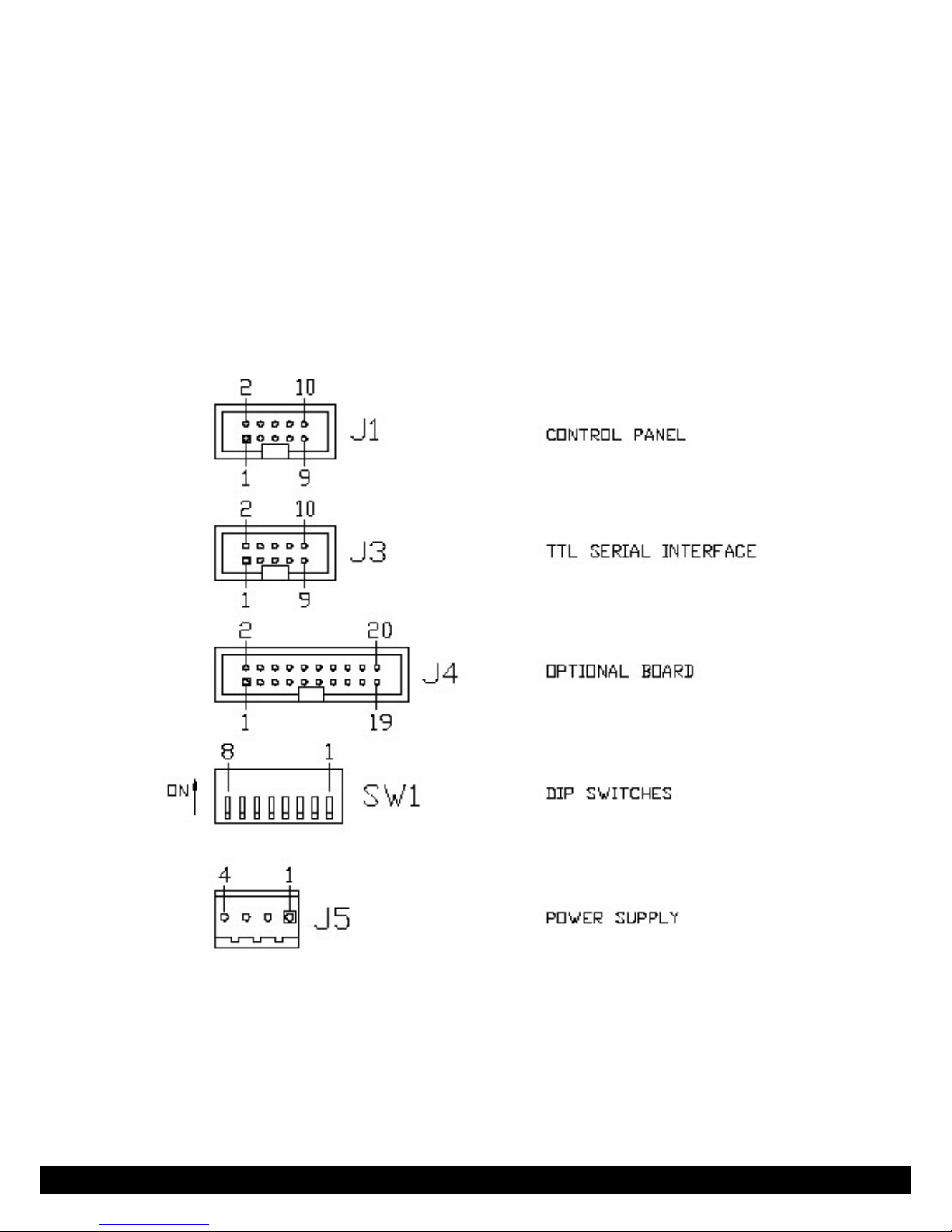
1.2 Connectors
See gure for connector pin numbering
Specication for logic levels are the following:
Output J1
low level: Vol < 0.5 Volt, lol = 5mA
high level: Voh > 4.5 Volt, loh = -5mA
Input J1
low level: Vil < 0.8 Volt, lil = -1.6mA
high level: Vol < 2.2 Volt, lih = 200μA

8DCA Intertel DCA Intertel
DCA Intertel 9 DCA Intertel
1.3 Sensor - Paper End
A reective sensor is used on the MP 2000 to detect the “PAPER END” condition.
When this sensor detects the end of the currently printed sheet, the following takes
place:
a: printing stops
b: the printer switches to “OFF LINE” (ON LINE indicator goes off)
c: PE (Paper End) indicator comes on.
d: carriage moves to middle of the printing span.
In order to resume printing, a new sheet should be loaded and then press the “ON
LINE” button.
When the printer runs out of paper, this condition is signalled via the serial port by
automatically issuing a “status byte” every 100 ms; bit 2 of status will be at logic “1”
as follows:
paper present: bit 2 = PE = 0
out of paper: bit 2 = PE = 1
The “PAPER END” sensor is also used to detect an “open mechanism” condition; in
fact when the mechanism is open the sensor no longer detects the sheet and actions
described in a, b, c and d take place. The carriage moves to the center until a new
sheet is introduced. The printer mechanism is closed and the “ON LINE” push-button is
pressed.
The “PAPER END” sensor can be disabled using control sequence ESC 8; if disabled,
printing can take place even on the bottom edge of the sheet. The disabling sequence
must be done before any out-of-paper condition develops, should the input buffer
contain some unprinted characters, the disabling sequence would only add up in the
queue never to be executed.
The sensor status can be polled at every line by requesting the printer status; when
PE is active, approximately 10 character lines can be printed before the sheet termina-
tes (with 1/6” line spacing).
Paper End Sensor

8DCA Intertel DCA Intertel
DCA Intertel 9 DCA Intertel
1.4 Sensor - Automatic Form/Paper loading and advance
The MP 2000 with serial interface has the ability to accept single forms.
By inserting a single form sheet (with a maximum of four copies) in the printer, the
paper will automatically go to “Top Of Form”. After the printing is nished, the paper/
form will automatically be ejected. To use this feature, the following software com-
mand settings have to be made.
MP 2000 TOF SETTING
-TOF driver with new board
-Possibility to read the TOF state by the host
-Automatic loading form/paper
-Form ejection over the feeding shaft
-Possibility to feed quickly forward/backward on “n” lines
OPERATIONS MADE ON DEFAULT
On default the printer ignores the PE detector. This allows the host to have the prin-
ter “ON-LINE” with or without paper. This condition is necessary to automatically load
form/paper.
The PE detector can be switched on when required.
COMMAND FOR AUTOMATIC FORM AND PAPER LOADING
ESC #l+b+d+n (“l” is an “L” in lowercase)
b = 0/1; Activates the beep signal when waiting for loading of paper.
d = Indicates the delay in increments of 5 msec. The PE detector is activated prior to
motor starting for the form feed function.
n = When TOF sensor is activated, the form goes up by multiples of 1/216 inches to
TOF.
The printer waits for the paper to be loaded at the back of the unit, then the inter-
lining motor will move until the TOF sensor is activated. From this position the paper
goes back n/216 inches, this new position is the Top Of Form.
The range of the parameter “n” is between 0 and 255 (approximately 0..30 mm).
This command must be sent before every automatic loading.
FORM EJECT COMMAND
ESC #e
The printer starts to eject the form until the PE detector is inactivated adding a “safety
time”. Before ejecting, the printer will print out the line buffer contents and disactiva-
tes the PE detector.

10DCA Intertel DCA Intertel
DCA Intertel 11 DCA Intertel
QUICK JUMP COMMAND
ESC #j+d+n
The printer makes a forward or backward feed of the paper of “n” lines.
d= 0 (binary or ASCII): forward feed
d= 1 (binary or ASCII): backward feed
n= number of lines (the dimension is set up by the proper command) to feed.
The paper feeding is limited according to the form dimensions. The dimension is set up
by the proper command (default 11 inches): it is not possible to go backward over the
top of the form or to go forward over the edge of the form.
Before the feeding of the paper, the printer will print out the contents of the line buf-
fer.
READING OF TOF STATUS
It can be read on bit “b1” of the status byte: 1 = TOF sensor covered.
The TOF sensor is detected by regular periods.
During the form setting, the sampling is quicker than normal, in order to have more
precise precision. In all the other operating conditions, the TOF signal is tested every
100 msec.
Table of contents
Other DCA Intertel Printer manuals


