DCA Intertel MP2005 User manual
1DCA IntertelDCA Intertel
V1.1 V1.1
User Manual
MP2005
Mobile Impact Printer
80 Column Dot Matrix
www.dca-group.com

2DCA IntertelDCA Intertel
V1.1
3DCA IntertelDCA Intertel
V1.1 V1.1
Table of Contans
1.Customer Care And Service 4
1.1 Warranty And Repair Service 4
1.2 Application Support 4
1.3 Notice 4
1.4 Warning 5
1.5 Limited Warranty 5
2. Description 6
2.1 Printer Overview 6
2.2 Printer Layout 7
3. Technical Specications 8
4. Installation 9
4.1 Unpacking 9
4.2 Procedure for Installation 9
4.2.1 Mechanical installation 9
4.2.2 Driver installation 9
4.3 Printer Setup 10
4.4 Caution! 12
4.5 Self Test 13
4.6 Indicators 14
4.7 Alarm and Indicator Functions 14
5. Printer Operation 15
5.1 Control Keys 15
5.2 Power Source 16
5.3 Paper Loading 17
5.4 Sensors 18
5.5 Maintenance 19
5.6 Inked Ribbon Cartridge Installation and
Replacement 20
6. Interfaces 21
6.1 Appendix A: 21
6.2 Appendix B: 22
6.3 Appendix C: 23

4DCA IntertelDCA Intertel
V1.1
5DCA IntertelDCA Intertel
V1.1 V1.1
1.Customer Care And Service
1.1 Warranty And Repair Service
To obtain warranty or repair service please contact DCA
Intertel at Phone: +31(0)172-604963 or
Fax: +31(0)172-605237 for a RMA number and shipping
instructions.
1.2 Application Support
If you have any questions on operating the MP-2005 or
require
information on specic applications, please contact DCA
Intertel.
Phone: +31(0)172-604963 or Fax: +31(0)172-605237.
1.3 Notice
The information contained in this document is subject to
changewithout notice. DCA Intertel makes no waranty
of any kind with regard to this material and shall not be
liable for errors contained herein or for consequential da-
mages in connection with the furnishing, performance, or
use of this material.
1.4 Warning
This equipment generates, uses, and can radiate radio
frequency energy, and may cause interference to radio
communications. It has been found to comply with the li-
mits for a Class A computing device, pursuant to Subpart
J of Part 15 of FCC rules, which are designed to provide
reasonable protection against such interference when
operated in a commercial environment. Operation of this
equipment in a residential area may cause such interfe-
rence that the user may be required to take measures to
correct.
1.5 Limited Warranty
The MP-2005 is warranted against manufacturing defects
in material for a period of one year from shipment to the
purchaser. Within this period DCA Intertel will repair or
replace the product without charge for material or la-
bor. Extended warranty is available. This warranty does
not cover damage or failure caused by abuse, improper
maintenance, or any repairs or modications other than
those provided by DCA Intertel. DCA Intertel makes no
other warranty, either expressed or implied, with respect
to this product and specically disclaims the implied war-
ranties of merchantaility and tness for a particular pur-
pose and shall not be responsible for any damages arising
out of or in connection with the use of this product.
6DCA IntertelDCA Intertel
V1.1
7DCA IntertelDCA Intertel
V1.1 V1.1
2. Description
2.1 Printer Overview
The MP- 2005 Mobile Printer is a ruggedized dot matrix
printer designed specically for mobile and portable ap-
plications. It can print in graphics mode along with diffe-
rent character fonts, both in draft ( 150 cps ) and NLQ (
25 cps ) mode. It has both tractor and friction feed me-
chanisms and can print on multi-copy paper
( 1 original and up to 3 copies ).
MP- 2005 is particularly suited for in vehicle applications,
due to its compact size and reduced weight. Power re-
quirements have been kept to a minimum bij means of
two DC motors with integrated optical encoders, and an
integrated driver board for precise positioning rather than
stepping motors.
MP- 2005 has a 2 Kbytes input buffer and comes with
an RS-232 serial interface. The MP 2000 driver software
supports DOS, Windows NT, Windows ‘95 and is compa-
tible to the commandset of EPSON LX 400/800.
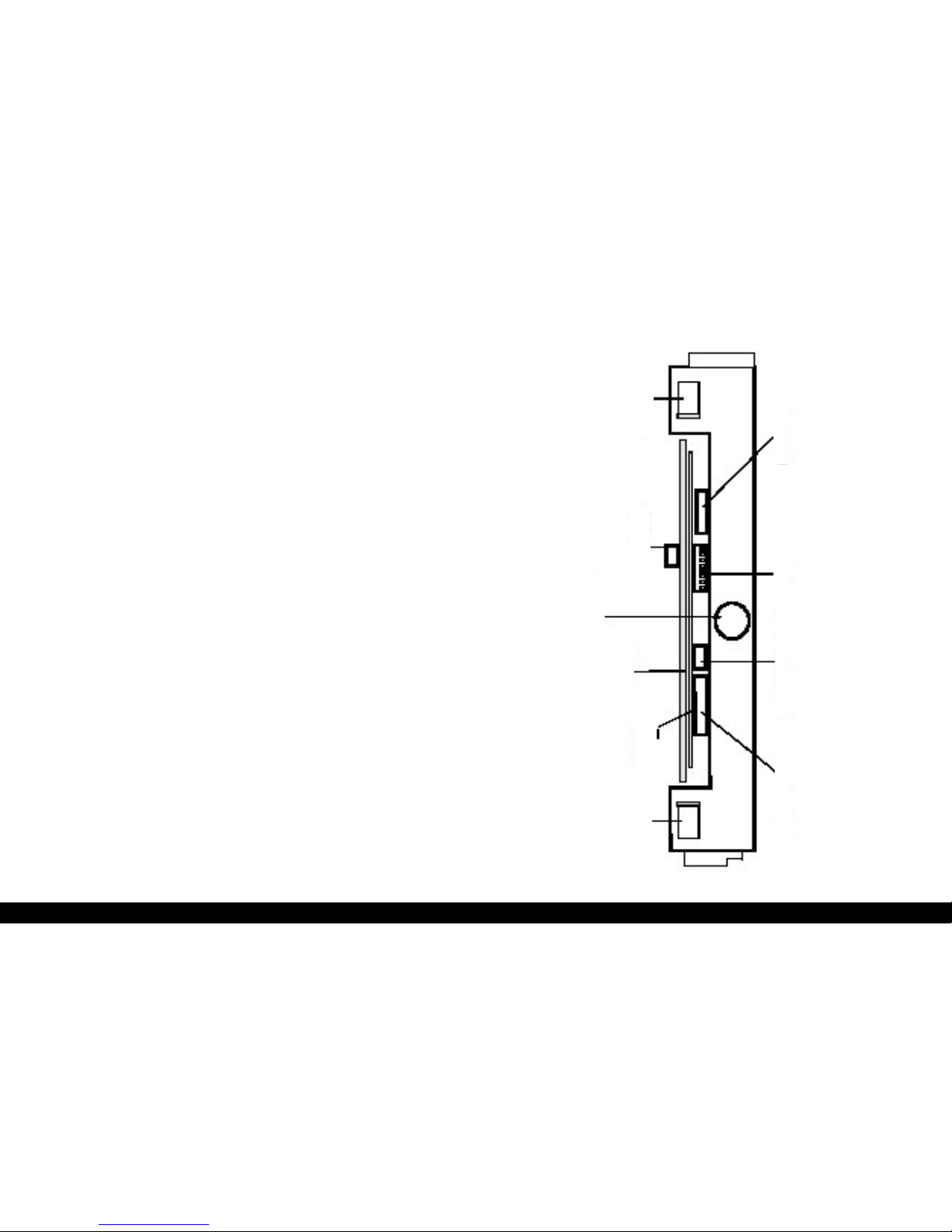
2.2 Printer Layout
Servermotor
Dip Switches
TTL Serial Interface Control Panel
TTL Parallel Interface
PRINTER HEAD
Power Supply
Power Board
Logic Board
HOT
Servermotor

8DCA IntertelDCA Intertel
V1.1
9DCA IntertelDCA Intertel
V1.1 V1.1
3. Technical Specications
Weight: 7 kg.
Power: 11-14,0 Volts DC
85 mA Standby
2.5 A at medium print density
Print: Impact Dot Matrix, 9 pins
Bi-directional with logic seeking
Paper Feed: Bi-directional, Sprocket and
friction
Copies: 1 original, 3 copies
Speed: 150 cps Draft
Paper Speed: 7 lines/second at 1/6”
13 lines/second continuous
Print Width: 8.25”
Paper Width: 8.93” pin to pin (sprocket)
3.5-8.5” tickets
Dots/Line: 1920 Max
Char. Set: IBM graphic bit image
Ribbon Life: Black 1.2 x 10⁶ characters
Interface: RS - 232
Operating temp: + 5 C.....+ 40 C
Non operating: -15 C ..... +70 C
MIL SPEC: 810 D/E Shock and Vibration
Printer Operation
4. Installation
4.1 Unpacking
Take the printer out of its shipping box and remove any
packing material. It is advisable to keep the shipping box
in case the printer needs to be reshipped or stored
elsewhere.
4.2 Procedure for Installation
4.2.1Mechanical installation
The MP-2005 can print in any position
4.2.2 Driver installation
MP-2005 driver software supports DOS, Windows NT,
Windows ‘95 and is EPSON LX 400/LX 800 compatible
and it can therefore be congured as such in the majority
of the software packages.

10 DCA IntertelDCA Intertel
V1.1
11 DCA IntertelDCA Intertel
V1.1 V1.1
4.3 Printer Setup
The MP-2005 can be congured by using the DIP-swit-
ches as shown in Fig. 1. The function of the DIP-switches
is depicted in Table 1.
TABLE 1 - DIP SWITCHES
Dip Switch Function
SW 1-1 Baud rate (see Table 2)
SW 1-2 Baud rate (see Table 2)
SW 1-3 for serial interface:
ON=XON/XOFF mode
OFF=DTR/DSR mode
SW 1-4 Character set
SW 1-5 Character set
SW 1-6 Character set
SW 1-7 CRLF mode: ON = enabled
OFF = disabled
SW 1-8 STAND-BY mode: ON = enabled
OFF = disabled
NOTE: Standard factory setting: SW 4,5,6, ON.
TABLE 2 - BAUD RATE SELECTION
Baud Rate SW 1-1 SW 1-2
1200 ON ON
2400 OFF ON
4800 ON OFF
9600 OFF OFF
CRLF mode = ON means that after every CR character
(carriage return) sent by the host, the printer automati-
cally performs a LF (Line Feed)
operation.
STAND-BY mode = ON means that after a certain pre-set
inactivity period, the printer goes to stand-by mode (re-
duced power drain).
If DIP-switch setting is switched ON while the printer is
on, the new conguration will come into effect only after
a subsequent printer turn-off and turn-on cycle.

12 DCA IntertelDCA Intertel
V1.1
13 DCA IntertelDCA Intertel
V1.1 V1.1
4.4 Caution!
* Do Not print without inked ribbon or paper, since this
leads to rapid printhead needle wear- out.
* Do Not move the printhead manually.
* Avoid mechanical shocks.
* Before starting to print, check that the inked ribbon
cartridge is correctly installed, the paper is loaded in the
proper position and the printer’s upper swiveling part is
locked to the lower one.
* If the printer has worked for some time, avoid touching
the printhead: it can be very hot. It is advisable to wait a
few minutes before attempting to replace the inked rib-
bon cartridge.
* Once the printer has been turned off, wait at least 10
seconds before turning it on again; this allows the inter-
nal reset circuitry to work properly.
* Do Not open the printer when it is operating.
NOTICE
Turn the computer on before the printer and turn the
printer off before the computer. This is only to avoid
dummy data to be sent by the computer printer du-
ring the on/off sequence.
NOTE:
The small size of the printhead did not allow for a
headpaper spacing adjustment device to be used in
single-copy or multi copy printing. Therefore, when
multi-copy printing is performed with a freshly in-
stalled inked ribbon cartridge, the rst printed pages
may have some ribbon marks.
4.5 Self Test
The printer is able to perform an internal self-check routi-
ne followed by a self-test printout.
To execute this procedure, simply keep the LINE feed
push-button pressed while the printer is powered up. The
test procedure prints a rst page with general information
about the MP-2005 and a second page of fonts.
CAUTION
DO NOT SELF TEST WITHOUT INKRIBBON OR PAPER.

14 DCA IntertelDCA Intertel
V1.1
15 DCA IntertelDCA Intertel
V1.1 V1.1
4.6 Indicators
POWER ON
This indicator lights when the printer is correctly powe-
red.
ON LINE
Turns on when the printer is ready to accept data. If the
ON LINE indicator ashes, the printer has switched to
STAND- BY mode.
PAPER END
Comes on when the printer is out of paper.
4.7 Alarm and Indicator Functions
The following description assumes that the control panel
with associated indicators and alarm is connected to the
printer.
ERROR indicator ashes
This means that the motor is locked due to some mecha-
nical reason; it is recommended to turn the printer off to
avoid battery pack overcharging.
5. Printer Operation
The MP-2005 control panel is tted with four control
keys, three indicators of which one is an alarm indicator.
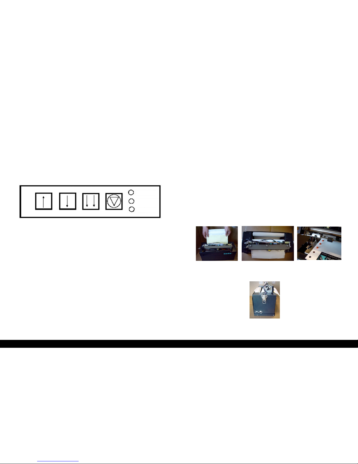
5.1 Control Keys
This key switches the printer on and off. When ON LINE,
the printer is ready to accept data from the computer.
Likewise when it is switched OFF LINE, the carriage auto-
matically moves to the center of the printer span. When
ON LINE the printer ignores the remaining push-buttons.
If the printer is switched ON LINE when the LINE FEED
push-button is activated, a demonstration test is perfor-
med.
ONLINE Paper End Error
This key advances the paper by one
sheet length (i.e. to the beginning of next
page).
This key advances the paper by one line.
This key retracts the paper by one line.
16 DCA IntertelDCA Intertel
V1.1
17 DCA IntertelDCA Intertel
V1.1 V1.1
5.2 Power Source
The MP-2005 requires a power source between:
* 11.0 - 14,0 VDC
* If the voltage drops below 10.5 VDC
( batteries drained ) the printer stops.
CONTROLPANEL
5.3 Paper Loading
MP-2005 can print on UNI A4/A5 size single sheet paper
forms or multi part paper forms or continuous fan-fold
paper with hole to hole spacing of 227mm (8.94”).
The procedure for correct paper loading is the following:
● Set the printer OFF LINE
● Open the printer by lifting lever A (Fig. 2.)
● Insert single-sheet module by placing it over the
printing plate, while checking if it is equally spaced
with respect to the printing area; in case of
continuous fan-fold paper, be sure that the
sprockets engage correctly in the holes provided for
near the edges.(see photo A,B and C)
● Close the swiveling printer top.(see photo D)
● Switch the printer ON LINE again.
DCA Intertel ONLINE
Paper End
ERROR
Photo A Photo B Photo C
Front side
Left side
Photo D

18 DCA IntertelDCA Intertel
V1.1
19 DCA IntertelDCA Intertel
V1.1 V1.1
CAUTION
If the printer has been printing for some time it is ad-
visable not to touch the printhead during paper loading or
inkribbon cartridge replacement, as it could be very hot.
5.4 Sensors
A reective sensor is used on MP-2005 for determining
the PAPER END condition. When this sensor detects the
end of the currently printed sheet, the following actions
take place:
1. printing stops.
2. the printer switches to OFF LINE
(ON LINE indicators goes off).
3. PE (PAPER END) indicators comes on.
4. carriage moves to middle of the printer span.
In order to resume printing, a new sheet should be loa-
ded and the ON LINE pushbutton should be pressed
The PAPER END sensor is also used to detect an “open
mechanism” condition. When the mechanism is open, the
sensor no longer sees the sheet and actions described
above take place. The carriage is likewise moved to the
center until a new sheet is introduced, the printer mecha-
nism is closed and the ON LINE push-button is pressed.
5.5 Maintenance
The MP 2005 does not require special maintenance, ex-
cept for the following:
-periodic cleaning, approximately every 10 million charac-
ters, of the printhead bearing rod with isopropylic alcohol
or similar.
- verication of the distance between printhead and prin-
ting plate (if the printer has suffered major shock or whe-
never an appreciable occurrence of bad quality printing
is experienced). The distance, measured by a thickness
gauge with the printer closed and no inked ribbon inter-
posed, should be 0.55 mm +/- 0.05 mm.
-periodic cleaning of the printer’s mechanism, in order to
avoid dust particles, paper clips and the like, can cause
mechanism malfunctions.
Paper End Sensor
Paper feeding direction
Table of contents
Other DCA Intertel Printer manuals


