CORNING ONE SD-LAN User manual
Other CORNING Network Hardware manuals
CORNING
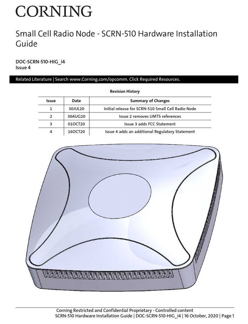
CORNING SCRN-510 Manual
CORNING
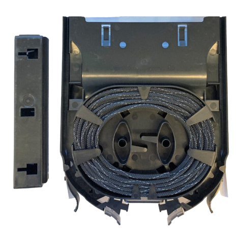
CORNING CCH-CS User manual

CORNING
CORNING Eclipse 01U User manual

CORNING
CORNING Everon 6000 G2 User manual

CORNING
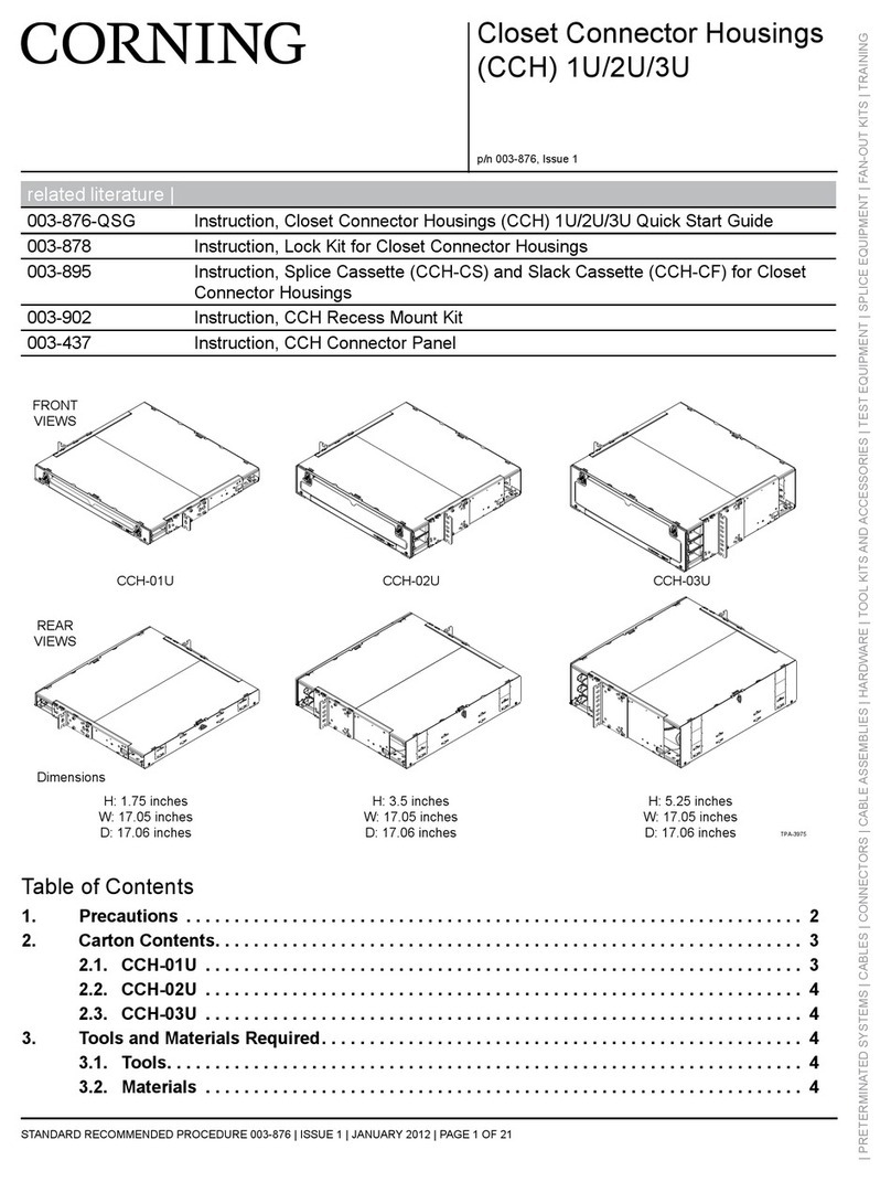
CORNING CCH 1U User manual

CORNING
CORNING PCH-96F-01U User manual
CORNING
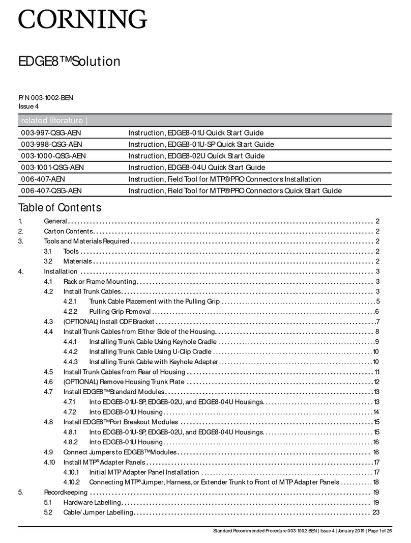
CORNING EDGE8 Series User manual

CORNING
CORNING EDGE User manual
CORNING
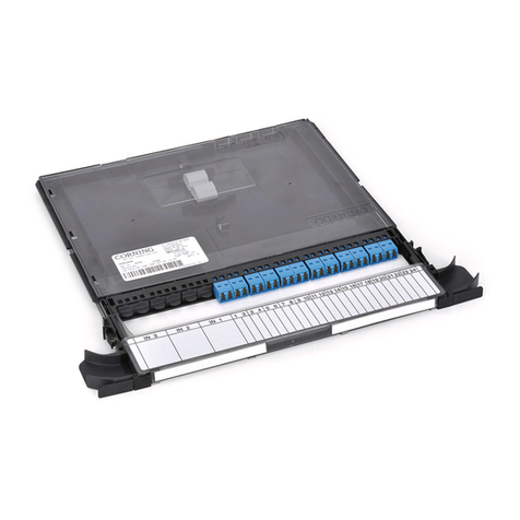
CORNING CCH-01U User manual
CORNING
CORNING Centrix User manual
CORNING
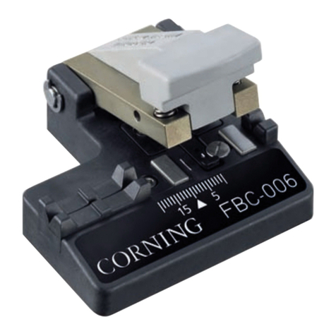
CORNING FBC-006 User manual
CORNING
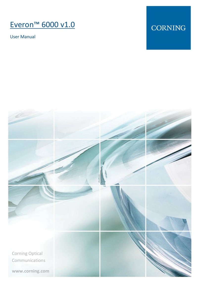
CORNING Everon 6000 v1.0 User manual
CORNING
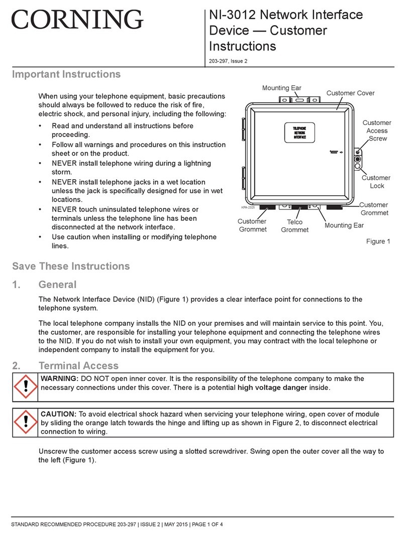
CORNING NI-3012 Reference guide
CORNING
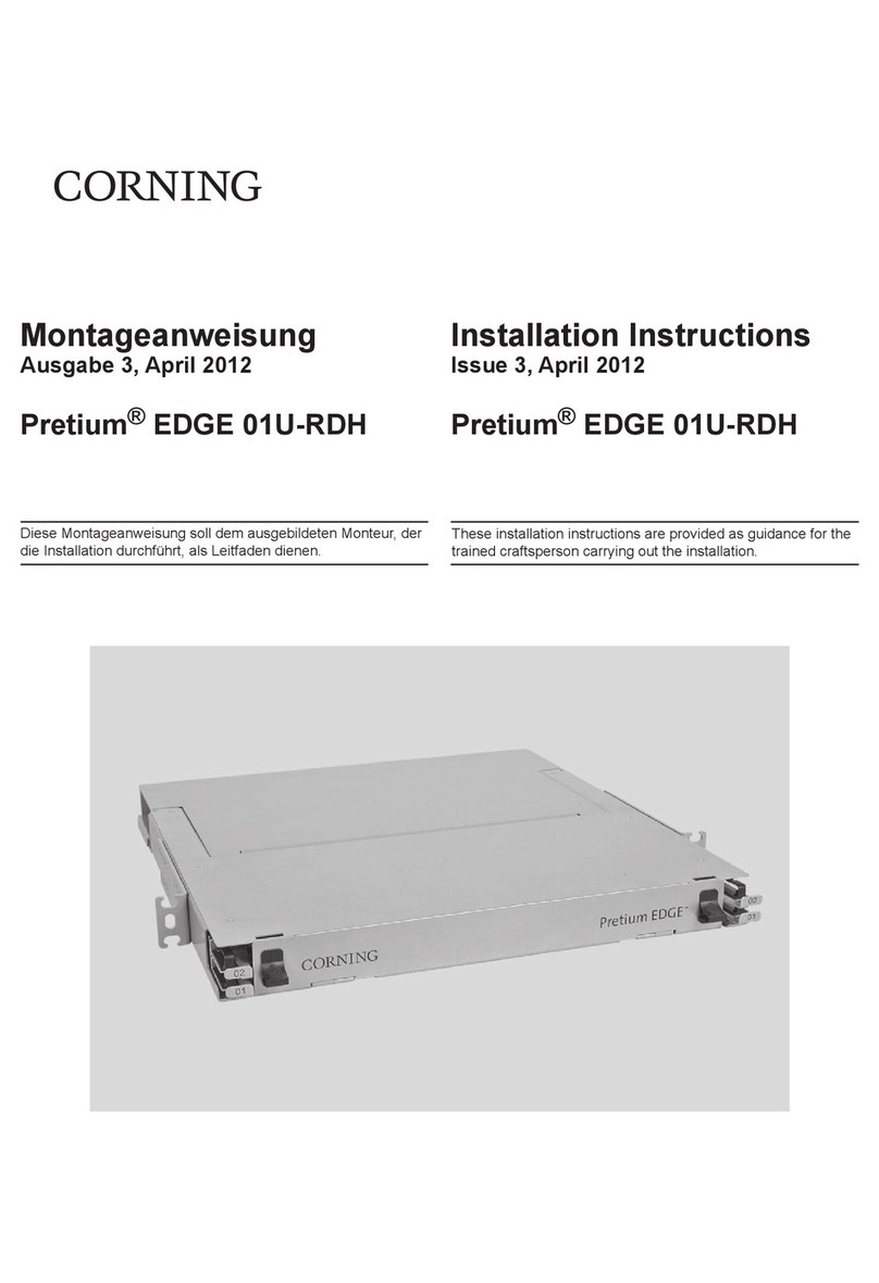
CORNING Pretium EDGE 01U-RDH User manual
CORNING
CORNING ONE User manual

CORNING
CORNING Centrix User manual
CORNING
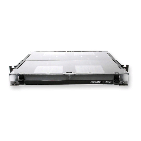
CORNING EDGE 1U User manual
CORNING
CORNING PS-MP Owner's manual

CORNING
CORNING ONE User manual
Popular Network Hardware manuals by other brands

Matrix Switch Corporation
Matrix Switch Corporation MSC-HD161DEL product manual

B&B Electronics
B&B Electronics ZXT9-IO-222R2 product manual

Yudor
Yudor YDS-16 user manual

D-Link
D-Link ShareCenter DNS-320L datasheet

Samsung
Samsung ES1642dc Hardware user manual

Honeywell Home
Honeywell Home LTEM-PV Installation and setup guide


