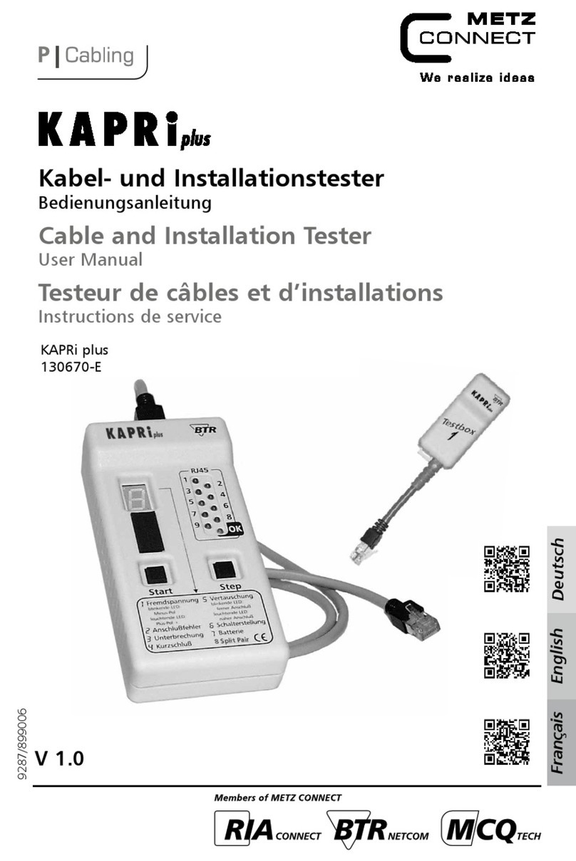
DCB BT-1 User manual

BT-1
TABLE OF CONTENTS
SECTION 1 - DESCRIPTION.............................................................................2
SECTION 2 - SPECIFICATIONS.......................................................................3
SECTION 3 - INSTALLATION...........................................................................4
SECTION 4 - OPERATION.................................................................................5
SECTION 5 - INTERFACE SIGNALS..............................................................18
SECTION 6- WARRANTY.................................................................................21
Data Comm or Business, Inc.
PO Box 6329
Champaign, IL 61826-6329 September 21, 2021
(217) 897-6600 Firmware Version: 5.8
www.dcbnet.com
8500008

1. DESCRIPTION
The BT-1 BERT tester is a digital RS-232 test set or modems, DSUs,
line drivers, multiplexers, terminals, printers, etc. Test unctions
include:
Bit Error, Block Error and Mirrored Bits tests
Polling tests (proprietary, DNP3 and Modbus)
The BT-1 can unction as a DNP3 or Modbus host or drop.
Timing tests
Function tests to toggle RTS, monitor DNP3 or Modbus
addresses
Synchronous or asynchronous operation
2

2. SPECIFICATIONS
2.1 General
DTE Inter ace with DB-25 male connector
Input pins: 3, 5, 6, 8, 15, 17
Output on pins 2, 4, 11, 20, 24 (pin 11 is tied to pin 20)
Test voltages: +v on pin 9, -v on pin 10
32 character LCD display (16 characters per line, 2 lines)
16 character keypad
2.2 DTE Timing
Asynchronous speeds o 75, 110, 300, 600, 1200, 1600, 1800, 2400,
4800, 7200, 9600, 14,400, 19,200,and 38,400 bps
Synchronous speeds to 64,000 bps
2.3 Physical/Electrical
4" W x 1.75" D x 7" H
120 VAC, 4 Watts
External 9 VDC, 500 ma power supply provided
2.4 Environmental
Operation: 0 to 65° C, 10 to 85% relative humidity
Storage: -40 to 85° C, 10 to 85% relative humidity
3

3. INSTALLATION
3.1 Unpacking
The ollowing is included with each BT-1:
BT-1 test set
External power supply, 9vdc, 500 MA
DB-25 male/ emale to DB-25 male/ emale ribbon cable
DE-9 male/ emale to DE-9 male/ emale ribbon cable
9 pin and 25 pin adapters and cables or monitor unctions
manual
3.2 Location
Place the BT-1 in an area where you can reach the ront panel keypad
and where you can reach to connect the cables. The BT-1 has an
external power supply that is plugged into a 120 VAC outlet. The
power cord length is about 6 eet.
3.3 Setup
The BT-1 is setup using the 16 key keypad. The irst step is typically
to set the operating parameters (speed, parity, etc) selected by using
the “SET PARM” key. Then the test is selected using the “SET TEST”
key.
Move around the screen using the arrow keys. The parameter to be
changed will lash on the LCD screen. Values are changed using the
“INCR” and “DECR” keys.
Some screens have the “>” character on the bottom right hand side.
This indicates the screen choices are more than 16 characters wide.
Use the right or le t arrow keys to view the extended screen.
The BT-1 can o ten be used to per orm a test right out o the box. The
de aults are as ollows:
9600 bps, 8 data bits, one stop bit, no parity
Bert test: async, QBF message, CTS low control
4

4. OPERATION
4.1 Keypad
BT-1 Keypad
TOP ROW OF KEYS:
RESET Resets the unit
RUN Starts running a test
WAIT Halts a test without stopping it. “Wait” toggles
the test o and on.
STOP Stops the test
SECOND ROW OF KEYS:
SET PARM Selects test parameters
SET TEST Selects test to run
DNP3 Direct access to DNP3 tests
CLR/ZERO Clears counters while test is running
THIRD ROW OF KEYS:
DECR Decrements a value
UP ARROW Move up a line on the LCD display
INCR Increments a value
ERR INJ Injects an error while a bert test is running
BOTTOM ROW OF KEYS:
LEFT ARROW Move le t on the LCD display
DOWN Move down a line on the LCD display
RIGHT ARROW Move right on the LCD display
MODBUS Direct access to MODBUS tests
5
RE-
SET RUN WAIT STOP
SET
PARM
SET
TEST DNP3 CLR/
ZERO
DECR INCR ERR
INJ
MOD
BUS

4.2 LCD Display Screen
The LCD screen is 2 lines, 16 characters per line. Most settings it on a
single screen. There are, however, a ew double wide screens. Under
SET PARM, the RTS HOLDOVER screen is double wide. The polling
set ups or both the host and the drop units, under SET TEST, are also
double wide. The Bert test results and the Polling test results also use
double wide screens. These screens have the “>” character at the
bottom o the screen. Use the right or le t arrow to get to the second
hal o the double wide setup screens. See example below:
1st screen 2nd screen
SENT RCVD SYNC
xxxx xxxx Good >
BLKER BITER SEC
<xxxx xxxx xxxx
4.3 Getting Started
Most unctions o the BT-1 are done with just a ew keys. The SET
PARM is used to set the speed, parity, word length, and test duration.
The SET TEST key selects the test to be per ormed. The ARROW keys
get you around the screen. The INCR and DECR keys change the
values on a screen. For example, the speed is changed using the INCR
and DECR keys. RUN initiates the test, WAIT halts the test, STOP
stops any test.
4.3.1 Setting Parameters
Use the SET PARM key to set parameters or timing, character length
and parity, RTS Holdover/TXD Holdo , test time, and Xon/Xo values.
Press the SET PARM to toggle rom one parameter to the next. Use
the ARROW keys to navigate around the screen and use the INCR and
DECR keys to change values
4.3.2 Timing
The timing parameter sets the asynchronous speed rom 75 to 38,400
bps, or to external clock. External clock is used when connecting the
BT-1 to synchronous communications devices (synchronous modems,
DSUs, etc.). Use the INCR and DECR keys to change the speed. Note
that it is possible to run a BERTA (async bert) test using external
clock.
6

4.3.3 Character
Character length can be 5, 6, 7 or 8 data bits. Parity can be even, odd
or none. Stop bits can be 1, 1.5 or 2 per character. Use the INCR and
DECR keys to change values.
4.3.4 RTS Holdover/TXD Holdo
The RTS holdover value keeps RTS on all the time i set to CONSTANT
ON. I one o the values ( rom 0 to 100 milliseconds) is picked, then
RTS will turn o a ter each poll or response and between each Bert
message, at the end o the message plus the millisecond time value. An
example o the use o this unction is when testing modems, DSU’s or
line drivers in switched carrier mode to determine i the modem, DSU
or line driver is dropping carrier detect during the transmission o the
last character o a message.
TXD Holdo is the period o time between turning RTS on and sending
the Bert message or a poll. The value o the holdo ranges rom 0 to
100 milliseconds.
4.3.5 Stop Test
The stop test parameter can be disabled to allow constant sending o
data, or the test can run or rom 10 seconds to 30 minutes, or until
there is an error. The stop on error will stop a Bert test when the
BT-1 sees a receive data error. The stop on error unction is an
excellent tool to use along with a data line monitor to trap data errors
when debugging equipment.
4.3.6 Xon/Xo
The Xon/Xo parameter allows or changing the low control characters
o Xon/Xo rom the typical hex 11 and hex 13 to other values.
4.4 Setting tests (SET TEST)
Use the SET TEST key to select the BertA, BertS, Poll, Time or
Function tests. Press the SET TEST key to toggle rom one test group
to the next.
7

4.4.1 BertA Tests
The BertA is the asynchronous bert (bit error rate test). This test is
used to determine i there are bit and/or block errors. When running
the BertA tests, the BT-1 expects Data Carrier Detect (pin8) and
Clear to Send (pin 5) to be asserted. Parameters include:
QBF – A “Quick brown ox” message. Please note that while many
test sets use “quick brown ox”, there is no standard message.
There is no standard or upper and lower case, spacing, the
inclusion (or not) o “0123456789” at the end o the message,
concluding the message with a space or no space, or ending a
carriage return/line eed or just a carriage return. The QBF
message used in the DCB BT-1 is most likely unique to the
BT-1.
QBF# “Quick brown ox” with a block number at the end, where the
block number ranges rom 000 to 999, then starts again at
block number 000. This test is use ul when generating data
or devices that have bu er memory. I some data is lost due
to circular bu er errors, data received out o order, etc, this
test plus a data line monitor quickly reveal the out o order
data.
ABC – Sends all printable characters
MBit This Mirrored Bits test has two options: 4-byte (4BYT), the
de ault, and 1-byte (1BYT) test message length. The delay
between test messages can be set in 1ms increments between
2ms, and 9ms, the de ault is 4 ms. Mirrored Bits is a
communications protocol developed by Schweitzer Engineering
Laboratories (SEL). It is a relay to relay logic communications
used by utilities to monitor and control relays.
ALT – Sends alternate mark/space character (“U”)
63 – Sends 63 bit pseudo random word
511 – Sends 511 bit pseudo random word
2047 – Sends 2047 bit pseudo random word
ALL – Sends all 256 hex values o an 8 bit character, hex 00 to hex FF
The test pattern selected can be sent continuously (CONT), at a 25%,
50%,or 75% duty cycle, or just once.
8

Flow control can be set to Clear to Send (CTS), Xon/Xo , or inverted
Clear to Send (CTS-H). These are choices or having the output o the
BT-1 halted by the attached communications equipment.
Input low control can be set to NONE, Busy High, Busy Low, or Xon.
Frequency or the bert to stop incoming data can be set to intermittent
(INTMT is about 8 seconds o , 2 seconds on in a repetitive cycle), or to
requent (FRQNT is about 2 seconds on, 2 seconds o ).
Test results are on 2 screens. The right and le t arrow keys are used to
move between the screens. Test results are as ollows:
1st screen 2nd screen
SENT RCVD SYNC
xxxx xxxx Good >
BLKER BITER SEC
<xxxx xxxx xxxx
4.4.2 BertS Tests
The BertS is the synchronous Bert (bit error rate test). This test is also
used to determine i there are bit and/or block errors. The six BertS
choices are the same as the BertA tests. These are QBF, ALT, 63, 511,
2047 and ABC. BertS tests do not include QBF#, Mbit or ALL.
BertS character patterns or QBF, and ABC are externally clocked but
use the start and stop bits on the data. The ALT, 63, 511 and 2047
tests do not include the start and stop bits. When running the BertS
tests, the BT-1 expects Data Carrier Detect (pin8) and Clear to Send
(pin 5) to be asserted.
Test results or the BertS tests are the same as or the BertA tests.
4.4.3 Poll Tests
DCB HOST
The polling tests require one BT-1 to be set as the host unit. The setup
screen is a double wide screen, where the 2 halves o the setup screen
are accessed using the right and le t arrow keys(> and <).
1st screen 2nd screen
Poll:DCB H ST-01
ASy 9600 1.0s>
TM =2.0s
<LEN=20->29
HOSTXX selects the number o remotes to poll, ranging rom 01 to 16.
ASy or 2Sy through 6Sy sets the polling test to be either async with
start and stop bits, or synchronous 8-bit data. The 2, 3, 4, 5 or 6Sy sets
9

the number o sync characters at the ront o the polling message. The
value o the sync character de aults to hex 16, which is the ASCII syn
character. The value o the sync character can be changed using the
SET PARM key, pressing it until the parameter option rolls to
SET: SYNC CHAR.
1.0s is the de ault time in seconds or the host to poll another drop a ter
getting a correct response rom a polled remote drop. This parameter
is used to simulate processing time between polls in a host computer.
Values range rom 0.0 to 5.0 seconds.
9600, etc., is the async speed o the polling test, i set to ASy. The
screen shows “” i set to xSy.
TMO is the timeout, and can range rom 0.5 seconds to 9.5 seconds.
Timeout is how long the host will wait or a poll response be ore
continuing to poll other drops. A timeout typically occurs when a
remote unit ails to respond to a poll, usually due to a data error.
LEN=20>29 is the number o characters sent in the poll. The
maximum number is 119. The data is “ABCDEF...”. This message is
echoed back rom the drop as a response to the poll.
Test results are as ollows:
1st screen 2nd screen
P LL RESP TM
xxx xxx xxx >
P Lxx RESP
< xxx xxx
The right hand side o the screen shows the results or each drop unit
that is being polled. In the above example, the POLxx re ers to one o
the drop numbers, which can range rom 01 to 16.
DCB DROP
Up to 16 drop units can be set up or polling. Each drop gets a separate
number, ranging rom 01 to 16.
Screen
Poll:DCB DR P=01
ASy 9600 0m
DROP=xx sets the drop number.
ASy is used to set the polling to async (ASY) or to set the number o
sync characters at the ront end o synchronous polling (2Sy to 6Sy).
10

9600, etc., is the async speed o the polling test, i set to ASy. The
screen shows “” i set to xSy.
xxxm Sets the time in milliseconds or the drop to delay the response to
the host poll. Values range rom 0 to 300ms in 25ms increments.
Test results are as ollows:
Screen
P Lxx RESP
xx xx r
DNP HOST
The DNP host poll is a request or a 16-bit analog input register in
group 30, variance 2, with the register address set by the "R:0001"
con iguration parameter on the right HOST con iguration screen.
1st screen 2nd screen
Poll:DNP H ST-01
ASy 9600 1.0s>
TM =2.0s R:0001
<ADR01=10000
HOSTXX selects the number o drops to poll, ranging rom 01 to 16.
9600 is the de ault async speed o the polling test. The speed can be
higher or lower using the INCR and DECR keys.
1.0s is the de ault time in seconds or the host to poll another drop a ter
getting a correct response rom a polled remote drop. This parameter
is used to simulate processing time between polls in a host computer.
Values range rom 0.0 to 5.0 seconds.
TMO is the timeout, and can range rom 0.5 seconds to 9.5 seconds.
Timeout is how long the host will wait or a poll response be ore
continuing to poll other drops. A timeout typically occurs when a
remote unit ails to respond to a poll, usually due to a data error.
R: is the RTU register that will be queried. To change values, use the
right or le t arrow keys until one o the digits lashes, then use the
INCR/DECR keys to change the value. Register 0001 is the de ault.
11

ADRxx=xxxxx is the drop number and DNP3 address. The de ault
value or 00 (host) is 10000. The de ault values or the other drops are
01=10100, 02=10200, and so on up to 16=11600. To change the values,
use the right and le t arrow keys until a digit lashes, then use the
INCR/DECR keys to change the values.
Test results are as ollows:
1st screen 2nd screen
P LL RESP TM
xxxx xxxx xxxx >
PLxx RESP DATA
<xxxx xxxx*xxxxx
The right hand side o the screen shows the results or each drop unit
that is being polled. In the above example, the PLxx re ers to one o
the drop numbers, which can range rom 01 to 16.
The title DATA on the top line o the 2nd screen shows three di erent
status messages: StsOK (status OK), O Ln (o -line), and OTHER (all
other status). When the host receives the drop response with the
Internal Indicators set to 0 (means the point exists) and the point
status on-line bit set to 1, the status shows StsOK. I the on-line bit is
set to 0, the status shows as O Ln. I there is no response or the point
does not exist, the status shows OTHER. The status messages apply
only to DNP3 host mode. The asterisk (*) indicates a poll response.
The DATA value will increment by one each time i the response is
rom a BT-1, starting at 00000, then 00001, 00002, 00003, etc.
DNP DROP
Up to 16 drop units can be set up or polling. Each drop gets a separate
re erence number, ranging rom 01 to 16. The DNP Drop will respond
to any poll rom any host address, and the response is returned to the
host's DNP address. The poll response reports a DNP 16-bit analog
input register in group 30, variance 2, with a register address set by
the "R:0001" on the right DROP con iguration screen.
1st screen 2nd screen
Poll:DNP DR P=01
ASy 9600 0m>
R:0001 D=00000
<ADR01=10100
DROP=xx sets the drop re erence number. This can be 01 through 16.
9600 is the async speed o the polling test.
0m Sets the time in milliseconds or the drop to delay the response to
the host poll. Values range rom 0 to 300ms in 25ms increments.
12

R: is the one and only register address that can be set or the DNP drop
D= is the value o the register. The de ault value is 00000. When the
drop is polled by a Host, the register value increments 1 a ter each poll.
At the Host BT-1, the received values will be 00000, 00001, 00002, etc.
ADR is the drop number and DNP3 address. The de ault values or the
drops are 01=10100, 02=10200, and so on up to 16=11600. To change
the values, use the right and le t arrow keys until a digit lashes, then
use the INCR/DECR keys to change the values.
Test results are as ollows:
Screen
PLxx RESP DATA
xxxx xxxx xxxxxr
The “r” lashes to show the test is running. The PLxx and RESP
numbers are the number o polls received and responses sent back to
Link Status Test ( V 5.8 irmware and above) When running in DNP
DROP mode, the BT1 responds to both the standard DNP HOST poll
and the DNP3 Link Status request. The main DNP DROP setup screen
includes an option to set the DFC bit lag to 0(de ault, 0x0B) or 1(0x1B)
in the Link Status response.
|----------------------------------+
| Poll:DNP DROP=01 -----|
| DFC0 9600 0m> -------- |
+----------------------------------+
DFC=0 is selected in the display image above. To change the DFC
setting, use the arrow keys to access the DFC0 then INC and DEC to
toggle between DFC0 and DFC1. When the BT1 is reset, DFC0 is the
de ault setting.
Note that the DNP DROP only decodes two incoming commands: 0xC4
(DCB Host poll) and 0xC9 (Link Status request). The Link Status
response is a 10-byte message that includes a Data Flow Control (DFC)
bit to signal whether the secondary station is ready or subsequent
primary station data commands. All other DNP3 commands are
ignored.
MB HOST
The MB host issues a poll to read one 16-bit holding register at the
address set by the "R:40001" on the right MB con iguration screen. The
13

actual drop holding register is one less than the number shown in the
last our digits o the "R:4xxxx" setting. For the de ault "R:40001",
holding register 0000 is requested.
1st screen 2nd screen
Poll: MB H ST-01
8N2 9600 1.0s>
TM =2.0s R:40001
<ADR01=101
HOSTXX selects the number o remotes to poll, ranging rom 01 to 16.
8N2 sets the character length, parity and stop bits. Other choices are
8E1 and 8O1.
9600 is the async speed o the polling test.
1.0s is the de ault time in seconds or the host to poll another drop a ter
getting a correct response rom a polled remote drop. This parameter
is used to simulate processing time between polls in a host computer.
Values range rom 0.0 to 5.0 seconds.
14

TMO is the timeout, and can range rom 0.5 seconds to 9.5 seconds.
Timeout is how long the host will wait or a poll response be ore
continuing to poll other drops. A timeout typically occurs when a
remote unit ails to respond to a poll, usually due to a data error.
R: is the register value to be queried by the polling host.
ADR is the Modbus address. Modbus hosts do not have addresses.
Only the Modbus drops have addresses. The highest possible Modbus
drop address is 247. De ault addresses are 01=101, 02=102 and so on
up to 16=116. To change the values, use the right and le t arrow keys
until a digit lashes, then use the INCR/DECR keys to change the
values.
Test results are as ollows:
1st screen 2nd screen
P LL RESP TM
xxxx xxxx xxxx >
PLxx RESP DATA
<xxxx xxxx xxxxx
The right hand side o the screen shows the results or each drop unit
that is being polled. In the above example, the PLxx re ers to one o
the drop numbers, which can range rom 01 to 16. The DATA ield will
increments (i the response is rom a BT-1) starting 00000, then 00001,
00002, 00003, etc.
MB DROP
Up to 16 drop units can be set up or polling. Each drop gets a separate
number, ranging rom 01 to 16. When polled, the MB DROP always
responds with the con igured holding register address and data
contents.
1st screen 2nd screen
Poll: MB DR P=01
8N2 9600 0m>
R:40001 D=00000
<ADR01=101
DROP=xx sets the drop number.
8N2 sets the character length, parity and stop bits.
9600 is the async speed o the polling test.
0m Sets the time in milliseconds or the drop to delay the response to
the host poll. Values range rom 0 to 300ms in 25ms increments.
15

R: is the register value to which the drop will respond i queried.
D= is the value o the register. The de ault value is 0000.
ADR is the Modbus address. The highest possible Modbus drop
address is 247. De ault addresses are 01=101, 02=102 and so on up to
16=116. To change the values, use the right and le t arrow keys until a
digit lashes, then use the INCR/DECR keys to change the values.
Test results are as ollows. The data value increments one per poll
during the test. The value starts at 00000 and then increments to
00001, 00002, etc.
Screen
PLxx RESP DATA
xxxx xxxx xxxxxr
4.4.4 Time Tests
Time tests are a collection o measurements, ranging rom Request to
Send/Clear to Send delay measurements, to round trip echo timing, to
character counting. The results o the tests are in milliseconds,
number o characters or positive or negative (high/low) signal levels.
The test are as ollows:
RTS/CTS DLY measures the time rom the BT-1 asserting RTS (pin 4)
until CTS (pin 5) is returned rom the attached equipment.
ECHO 1 CHAR measures the time it takes or a single character to be
sent rom the BT-1 and echoed back to it.
ECHO CONT measure the time it takes or characters to be sent rom
the BT-1 and echoed back to it.
CHAR COUNT counts the number o characters received over a
number o seconds.
CHAR LOOP counts the number o characters received on the RXD
input and keeps track o the number o parity and raming errors
detected.
SHORT BREAK sends out a break, or positive voltage level, on the
transmit data lead or 1/2 second.
16

LONG BREAK sends out a break, or positive voltage level, on the
transmit data lead or 2 seconds.
MARK/SPACE sends out a constant mark (negative voltage), constant
space (positive voltage) or alternating mark/space. The INCR and
DECR keys can be pressed while the test is running the change
between the three values.
MODEM RATE measures the data rate o the clock input to pin 15,
rounded o to the nearest typical modem speed. Typical speed results
are 1200, 1800, 2400, 4800, 7200, 9600, 19200, 38400.
CLOCK RATE measures the data rate o the clock input to pin 15
based on a 100 microsecond internal timer. The BT-1 sends out a ixed
number o characters, measure the time it takes to send them and then
calculates the rate o speed. At 9600, the BT-1 gives a result o 9597 or
9606. At 1200 bps, the resolution is .14 bps, and at 56000 bps the
resolution is 314 bps.
BIT SLIP is used to detect bit error in synchronous systems where the
errors are the result o bit slippage. The test measures bit slip or bit
gain. The BT-1 sends out a pattern o 001100110011, etc. and looks or
a gain or loss o one o the bit pairs. The bit slip test can speci ically
isolate bit gain or slip. The bit slip test can be run in loopback or rom
one BT-1 to another. The BIT SLIP test is use ul or detecting timing
problems. For example, i one were using 56Kbps DS-0 RS232
channels on a channel bank, and the channel banks were
independently timed, rather than one channel bank drop timed to the
other, it is likely that there will be bit slips, as the 2 independent clocks
move in and out o phase with respect to each other.
4.4.5 Function (FCN) Tests
The Function, or FCN tests, tests are a collection o measurements,
ranging rom Request to Send/Clear to Send delay measurements, to
round trip echo timing, to character counting. The results o the tests
are in milliseconds, number o characters or positive or negative
(high/low) signal levels. The test are as ollows:
DNP TO is a monitor unction. It shows the DNP “TO” address in a
poll. I it is monitoring a host, this test will show all the DNP address
that are being polled. I the BT-1 is monitoring a drop, it will show the
address o the host that is being answered.
DNP FROM is a monitor unction that shows the DNP “FROM”
address. I monitoring the host, it shows the host address. I the BT-1
is monitoring a drop, it will show the drop address.
17

MB RTU is a monitor unction. It shows the Modbus addresses that
are being polled.
RTS+ toggles the RTS lead (pin 4) rom an o state to an on state or a
period ranging rom 0.5 milliseconds to 30 milliseconds. It does this
once, or 1, 2 , 5 or 10 times per second.
RTS toggles the RTS lead (pin 4) rom an on state to an o state or a
period ranging rom 0.5 milliseconds to 30 milliseconds. It does this
once or 1, 2, 5 or 10 times per second.
18

5. INTERFACE SIGNALS
5.1 RS-232D / V.24 Inter ace (DB-25P)
Pin Signal Name In/Out
1 Frame Ground ---
2 Transmit Data OUT
3 Receive Data IN
4 Request to Send OUT
5 Clear to Send IN
6 Data Set Ready IN
7 Signal Ground ---
8 Data Carrier Detect IN
9 + test voltage OUT
10 test voltage OUT
11 Busy (tied to pin 20) OUT
15 Transmit bit clock IN
17 Receive bit clock IN
20 Data Terminal Ready OUT
24 External Transmit Clock OUT
Note: Pin 24 external clock rate is 16 times the async
rate set in the “Set Parm” menu. For example, i the
async rate is set to 1200, then the clock rate on pin 24
is 16 times 1200, or 19,200 bps.
5.2 Accessories
The ollowing accessories are included with each BT-1 test set. They
provide the versatility required or connection in DNP3 and Modbus
polling or monitoring applications as well as more conventional
RS232 BERT tests.
5.2.1 Cables
25 pin MF/MF ribbon cable, DCB P/N: 9801003
9 pin MF/MF ribbon cable, DCB P/N: 9801035
RJ45 to RJ45 patch cable, 3 t., black, DCB P/N: 9500056
RJ45 to RJ45 crossover cable, 5 t., red, DCB P/N: 9500105
19

5.2.2 Adapters
DNP Rx, DCB P/N: 9802084
DNP 25, DCB P/N: 9802083
DNP 9, DCB P/N: 9802085
5.2.3 Applications
9 pin Connection as Host or Drop
20
RJ45
3
4
BLK
RED
DB-25S
3
7
RJ45
1
3
4
BLU
BLK
RED
DB-25P
2
3
7
RJ45
1
3
4
BLU
BLK
RED
DE-9P
3
2
5
BT-1 DNP 25 DNP 9
25 pin ribbon
cable
Black or Red
RJ to RJ cable 9 pin ribbon
cable i required
Table of contents
