DCS RGTC-305 User manual

PROFESSIONAL 30” FIVE BURNER
SELF-CLEAN GAS RANGE
Installation Guide
MODELS:
RGTC-305
RGTC-305
Installation Guide


A MESSAGE TO OUR CUSTOMERS
1
Thank you for selecting the DCS Professional 30” Self-Clean Gas Range. Because of this appliance’s unique
features we have developed this Installation Guide. It contains valuable information on how to properly install
your new appliance for years of safe and enjoyable cooking.
For your convenience, product questions can be answered by a DCS Customer Care Representative
or by mail:
Fisher & Paykel Appliances, Inc.
Attention: DCS Customer Care
5900 Skylab Road
Huntington Beach, CA 92647
www.dcsappliances.com
WARNING
Improper installation, adjustment alteration, service or maintenance can cause property damage, injury or death.
Read the installation, operating and maintenance instructions thoroughly before use, installing or servicing this
equipment.
WARNING
If the information in this manual is not followed exactly, a fire or explosion may result causing property damage,
personal injury or death. Do not store or use gasoline or other flammable vapors and liquids in the vicinity of this or
any other appliance.
WARNING
To reduce the risk of injury to persons in the event of a cooktop grease fire, observe the following: Turn burner off
first. Smother flames with a close-fitting lid, cookie sheet, metal tray, baking soda or use a dry chemical or foam-type
fire extinguisher. Be careful to prevent burns. If the flames do not go out immediately, evacuate and call the fire
department. Never pick up a flaming pan - You may be burned. DO NOT USE WATER ON GREASE FIRES, including
wet dishcloths or towels - a violent steam explosion will result. Use an extinguisher ONLY if:
1. You know you have a Class ABC extinguisher, and you already know how to operate it.
2. The fire is small and contained in the area where it started.
3. The fire department is being called.
4. You can fight the fire with your back to an exit.
FOR YOUR SAFETY
If You Smell Gas:
1. Do not try to light any appliance.
2. Do not touch any electrical switch; do not use any phone in your building.
3. Immediately call your gas supplier from a neighbor’s phone. Follow the gas supplier’s instructions.
4. If you cannot reach your gas supplier, call the fire department.
5. Installation and service must be performed by a qualified installer, service agency or the gas supplier.
PLEASE RETAIN THIS MANUAL FOR FUTURE REFERENCE.

2
TABLE OF CONTENTS
INTRODUCTION 3
SAFETY PRACTICES AND PRECAUTIONS 4-6
PLANNING THE INSTALLATION 7-8
UNPACKING AND HANDLING 8-10
VENTILATION REQUIREMENTS 11
INSTALLING ANTI-TIP DEVICE 12
CABINET PREPARATION 13-14
BACKGUARD INSTALLATION 15
ELECTRICAL CONNECTIONS 15
GAS HOOK-UP 16
TEST AND ADJUSTMENTS 17
CLEANING EXTERIOR SURFACES 18
INSTALLER FINAL CHECKLIST 18
HOW TO OBTAIN SERVICE 19
WARRANTY 20-21

3
INTRODUCTION
The Patented Dual Flow BurnersTM on the DCS RGTC Range allow for consistently lower simmer temperatures and
have a high output of 17,500 Btu/hr, with two burners at 12,500 Btu/hr. The large capacity gas convection oven
of the RGTC is equipped with an in-oven gas infrared broiler.
IMPORTANT INSTALLATION INFORMATION
The RGTC Range is tested in accordance with ANSI Z21.1 Standard for Household Cooking Gas Appliances. These
ranges must be installed in conjunction with a suitable overhead vent hood (see step 2 for ventilation
requirements). Due to the professional high heat capacity of this unit, particular attention should be paid to the
hood and duct work installation to ensure it meets local building codes. To eliminate risk of burns or fire by
reaching over heated surface units, cabinet storage located above the surface units should be avoided.
Check local building codes for the proper method of range installation. Local codes vary. Installation, electrical
connections, and grounding must comply with all applicable codes. In the absence of local codes, the range
should be installed accordance with the National Fuel Gas Code ANSI Z223-1 and National Electrical Code
ANSI / NFPA 70-1990. Be sure that the unit being installed is set up for the kind of gas being used. The gas
ranges are shipped from the factory set and adjusted for natural gas or LP (propane), depending on the specific
model ordered. Verify that the range is compatible with gas supply at the installation site before
proceeding further. Return range to dealer if unit is not set for the gas supplied at the site.

4
SAFETY PRACTICES AND PRECAUTIONS
When properly cared for, your new DCS Appliance has been designed to be a safe, reliable cooking appliance.
When using this restaurant caliber appliance, use it with extreme care, as this type appliance provides intense
heat which can increase the accident potential. Basic safety precautions must be followed when using kitchen
appliances, including the following:
■
Read the Use and Care Manual which came with this appliance thoroughly before using your new appliance. This
will help to reduce the risk of fire, electric shock, or injury to persons.
■
Begin by insuring proper installation and servicing. Follow the installation instructions in this manual. Be sure to
have a qualified technician install and ground this appliance before using.
■
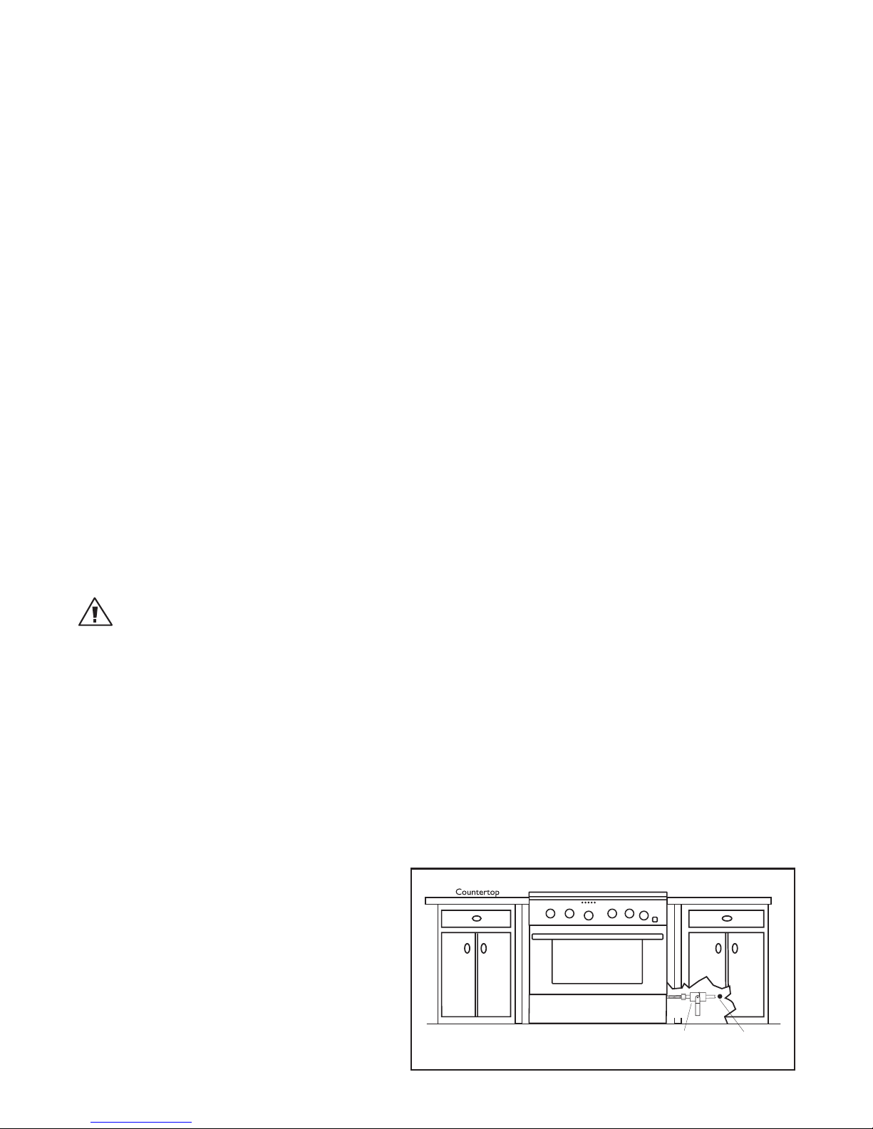
Have the installer show you where the gas supply shut-off valve is located so you will know how and where to
turn off the gas to the appliance.
■
If you smell gas, the installer has not done a proper job of checking for leaks. You can have a small leak and
therefore a faint gas smell if the connections are not completely tight. Finding a gas leak is not a “do-it-yourself”
procedure. Some leaks can only be found with the burner control in the “ON” position and for your protection it
must be done by a qualified service technician.
■
If by some chance a burner goes out and gas escapes, open a window or a door to let the room air out. Do not
attempt to use the appliance until the gas has had time to dissipate. Follow the instructions on page 1, “For your
safety – if you smell gas”.
■
This appliance has been factory assembled for natural or LP gas. It should be correctly adjusted from the factory
for the type of gas that is used.
■
Do not repair or replace any part of this appliance unless it is specifically recommended in this manual. All other
servicing should be referred to a qualified technician.
■
Children should not be left alone or unattended in an area where appliances are in use. They should never be
allowed to turn knobs, push buttons, sit or stand on, and/or touch any part of an appliance while in operation.
■
Children in walkers, or children crawling can be attracted to the round oven door handle and may grab and open
the oven door. This can result in injury from the door being pulled open on a child, or severe burns if the oven is
in use and hot.
WARNING:
Do not store items of interest to children above or at the back of any appliance. Children could be seriously injured
if they should climb onto the appliance to reach these items.
■
Never store anything in the oven or on the cooktop. Flammable materials can catch fire, plastic items may melt or
ignite and other types of items could be ruined.
■
Do not hang articles from any part of the appliance or place anything against the oven. Some fabrics are quite
flammable and may catch on fire.
■
If the appliance is near a window be certain the curtains do not blow over or near the cooktop burners; they
could catch on fire.
■
Do not use water on grease fires. Turn all burners “OFF”, then smother the fire with baking soda or use a dry
chemical or foam-type fire extinguisher.
■
Never let clothing, pot holders, or other flammable materials come in contact with, or too close to, any burner or
burner grate until it has cooled. Fabric may ignite and result in personal injury.
■
Be certain to use only dry pot holders: moist or damp pot holders on hot surfaces may cause burns from steam.
Do not use a towel or other bulky cloth in place of pot holders. Do not let pot holders touch hot burners, or
burner grates.

5
SAFETY PRACTICES AND PRECAUTIONS
■
For personal safety, wear proper apparel. Loose fitting garments or hanging sleeves should never be worn while
using this appliance. Some synthetic fabrics are highly flammable and should not be worn while cooking.
■Do not use aluminum foil to line any part of the oven or cooktop. This will cause heat to be trapped underneath
it. This trapped heat can upset the cooking performance and can damage the finish of the oven or the cooktop
parts.
■This appliance is for cooking. Never use the oven or cooktop to warm or heat a room. This could damage the
cooktop or oven parts.
■
When using the cooktop: Do not touch the burner grates or the immediate surrounding area. Areas adjacent to
the burners may become hot enough to cause burns.
■
When using the oven: Do not touch the interior surfaces of the oven, the exterior area immediately surrounding
the door or the back trim. The surfaces directly above the oven door may be hot if the oven has been operated
with the door open, or if something has prevented the door from sealing.
■
Never leave the cooktop unattended when using high flame settings. When cooking with high flame settings,
boil overs may cause smoking and greasy spill overs may ignite. More importantly, if the burner flames are
smothered by a severe boil over which effects the igniter, unburned gas will escape into the room.
■
Only certain types of glass, heat-proof glass-ceramic, ceramic, earthen ware, or other glazes utensils are suitable
for cooktop use. This type of utensil may break with sudden temperature changes. Use only on low or medium
flames settings according to the manufacturer’s directions. The use of professional utensils is recommended.
■
Do not heat unopened food containers; a build up of pressure may cause the container to burst.
■
During cooking, set the burner control so that the flame heats only the bottom of the pan and does not extend
beyond the bottom of the pan. This could heat and/or melt the handles, and may increase cooking time.
■
Always use utensils that have flat bottoms large enough to cover the burner. The use of undersized utensils will
expose a portion of the flame to direct contact and may result in ignition of clothing.
■
To minimize burns, ignition of flammable materials and unintentional spill overs, position handles of utensils
inward so they do not extend over adjacent work areas, cooking areas, or the edge of the cooktop.
■
Hold the handle of the pan to prevent movement of the pan when stirring or turning food.
■
Grease is flammable. Let hot grease cool before attempting to handle it. Avoid letting grease deposits collect
around the cooktop burners. Clean after each use or boil over.
■
For proper lighting and performance of the cooktop burners, keep the burner ports clean. It may be necessary to
clean these when there is a boil over or when the burner does not light, even though the electronic igniters click.
WARNING! NEVER cover any slots, holes or passages in the oven bottom or cover an
entire rack with materials such as aluminum foil. Doing so blocks airflow through the oven and may
cause carbon monoxide poisoning. Aluminum foil linings may also trap heat, causing a fire hazard.
WARNING! NEVER use this appliance as a space heater to heat or warm the room.
Doing so may result in carbon monoxide poisoning and overheating of the oven.

6
SAFETY PRACTICES AND PRECAUTIONS
■
Clean the cooktop with caution. Avoid steam burns; do not use a wet sponge or cloth to clean the cooktop while
it is hot. Some cleaners produce noxious fumes if applied to a hot surface. Follow directions provided by the
cleaner manufacturer.
■
Be sure all the range and/or cooktop controls are turned off and the appliance is cool before using any type of
aerosol cleaner on or around the appliance. The chemical that produces the spraying action could, in the
presence of heat, ignite or cause metal parts to corrode.
■
Place oven racks in desired position while the oven is cool. If a rack must be moved while the oven is hot, do not
let the pot holders contact the hot interior lining of the oven.
■
Use care when opening the oven door; let hot air or steam escape before removing or replacing foods.
■
Do not rub, damage, move or remove the door gasket. It is essential for a good seal during baking. Wash the
gasket with hot water only.
■
Clean the ventilator hood and filters above the range or cooktop frequently so grease from cooking vapors does
not accumulate on them. The filter can be cleaned in a dishwasher or DishDrawer. Follow directions provided
by ventilation manufacturer for cleaning.
■
Turn the ventilator “OFF” in case of fire or when intentionally “flaming” liquor or other spirits on the cooktop. The
blower, if in operation, could unsafely spread the flames.
■
DO NOT obstruct the flow of combustion or ventilation air to the appliance. Be sure a fresh air supply is
available.
■
For safety reasons and to avoid damage to the appliance never sit, stand, or lean on the oven door or cooking
surface.
■
Service should only be done by authorized technicians. Technicians must disconnect the power supply before
servicing this appliance.
WARNING:
California Proposition 65 - The burning of gas cooking fuel generates some by-products which are known by the
State of California to cause cancer or reproductive harm. California law requires businesses to warn customers of
potential exposure to such substances. To minimize exposure to these substances, always operate this unit
according to the instructions contained in this booklet and provide good ventilation to the room when cooking
with gas.
RECOMMENDATIONS ON HOOK-UP TO GAS SUPPLY:
A manual valve must be installed external to the appliance, in an accessible location from the front for the
purpose of shutting off the gas supply. The supply line must not protrude beyond the back of the unit. Make
sure the gas supply is turned off at the wall valve before connecting the appliance.
The gas supply connections should be made by a qualified technician and in accordance with local codes or
ordinances. In the absence of a local code, the installation must conform to the latest edition of the National
Fuel Gas Code ANSI 223.1.
NOTE:
This product must be installed by a licensed plumber
or gas fitter when installed within the
Commonwealth of Massachusetts.
NOTE: (mandatory for the State of Massachusetts)
Alternate method of supplying gas must be installed
into the unit.
Installer supplied shut-off valve
must be easily accessible inside
cabinetry.
Gas Supply

7
PLANNING THE INSTALLATION
IMPORTANT INSTALLATION INFORMATION
The RGTC-305 is tested in accordance with ANSI Z21.1 Standard for Household Cooking Gas Appliances.
The range must be installed in conjunction with a suitable overhead vent hood. (See ventilation requirements,
page 11). Due to the professional high heat capacity of this unit, particular attention should be paid to the hood
and duct work installation to ensure it meets local building codes. To eliminate risk of burns or fire by reaching
over heated surface units, cabinet storage located above the surface units should be avoided.
All range models with less than a 12” clearance between combustible material and the back edge of the range,
require the installation of one of the two offered Wall Mount Backguards – see page 15.
Check local building codes for the proper method of range installation. Local codes vary. Installation, electrical
connections, and grounding must comply with all applicable codes. In the absence of local codes, the range /
cooktop should be installed in accordance with the National Fuel Gas Code ANSI Z223.1 and National Electrical
Code ANSI / NFPA 70-1990.
Be sure that the unit being installed is set up for the kind of gas being used. The gas range is shipped from the
factory set and adjusted for Natural Gas or LP (propane), depending on the specific model ordered. Verify
that the range is compatible with the gas type at the installation site before proceeding
further. Return range to dealer if the unit is not set for the gas supplied at the site.
Fig. 01
28-1/8”
10-1/8”
Wall Mount Full
Backguard
(Model No.
BGS-3030)
Wall Mount
Low Backguard
(Model No.
BGS-1230)
1-5/16”
1-5/16”

8
PLANNING THE INSTALLATION
RECOMMENDED INSTALLATION INSTRUCTION (when using BGS-3030 Backguard
which is sold separately)
Install components in the following order:
A. Vent Hood
B. Backguard System
C. Range
1. Locate and level range according to range installation instructions.
2. Measure distance from floor to top of island trim on range, adding 1/8” for backguard clearance.
3. Transfer this measurement to the wall. This will mark the bottom of your backguard.
4. From this line measure 28-1/8” up wall to mark the top of 30” backguard. This is the minimum height that the
bottom of your vent hood can be installed.
5. Follow vent hood manufacturer’s installation instructions to install vent hood.
6. Follow backguard installation instructions to install backguard.
7. Connect gas and electric connections and slide range into position.
CAUTION:
Proper equipment and adequate manpower must be used in moving the range to avoid damage to the unit or the
floor. The unit is heavy and rests on adjustable steel legs.
WARNING:
DO NOT lift range by the oven door handles or drip pan handle!!
MOVING AND PLACING THE RANGE
The range has a shipping weight of approximately 408 pounds or 354 pounds after removal of packing materials.
It is recommended that the door, grates and front kick panel be removed to facilitate handling. This will reduce
the weight to about 230 pounds.
It may be necessary to remove the oven doors and knobs to pass through some doorways. With the doors and
knobs removed, 29-3/8” wide opening is required. Without removing the door, 30” wide opening is required.
Remove the outer carton and packing material from the shipping base.
UNPACKING AND HANDLING

9
UNPACKING AND HANDLING
CAUTION:
Before using the range, be sure to remove shipping spacer insert in
the broiler (see Fig. 03).
To remove the kick panel:
Removing two screws at the top and pulling forward. The range
is held to the skid by L-brackets in the front behind the kick
panel, (Fig. 02) and two L-brackets located on the bottom flange
of the range back (Fig. 04). After removing the brackets, the range
must be lifted and removed from the skid.
Due to the weight, a dolly with soft wheels should be used to
move this unit. The weight must be supported, uniformly across
the bottom (Fig. 05).
WARNING!
Do not lift oven door by the handle - will cause damage! Be sure the
oven and door are cool before you begin to remove the door!
Left Rear Shipping
Screws
Fig. 04
22"
Leveling Legs
Range Must
be Uniformly
Supported
on Braces
Fig. 05
Left Rear
Shipping Screws
Range Must be
Uniformly
Supported on
Braces
LEVELING LEGS
Fig. 02
Kick Panel
Fig. 03
Shipping
Spacer
MOVING AND PLACING THE RANGE (continued)
Electric and gas connections should be made before the range is
slid into the cabinet opening (see pages 13). If installing a full
backguard with the range, it should also be installed before the
range is placed in its final position (refer to pages 15). For proper
performance, the professional range should be level. To achieve a
flush fit of the range to adjoining countertops, it will be necessary
to have level cabinets (front to back, and left to right across
opening of the range). After checking the countertops are level
and before sliding the range into place, measure the distance from
the floor to the top of the counter work surface in the rear left and
right corners. Adjust the corresponding rear corner of the range to
an equal height of the counter, as the rear leveling legs are not
accessible once the range is pushed into place. Once the range is
in place, the front leg levelers can be accessed to level the front of
the range. Replace the kick panel and oven doors by reversing the
procedure described previously. It is important that the two
screws retaining the kick panel are secure to prevent accidental
access to live electrical components and wires (Fig. 02).
Anti-tip device should be installed (see page 12 for instructions).
The professional range should be transported by a dolly close to its
final location. The range can be tipped back and supported on the
rear legs while the dolly is removed. The floor under the legs
should be protected (wood strips, carpet, paneling, etc.) before
pushing the unit back into position.
Note:
For ease of installation, be sure to install venthood and backguard
system before sliding range into position.
Screw hole
L-bracket

10
UNPACKING AND HANDLING
Fig. 06
OVEN HINGE ASSEMBLY
Fig. 07
HINGE RETAINER CLIP IN UNLOCKED POSITION
Fig. 09
HINGE RETAINER CLIP IN LOCKED POSITION
Fig. 08
HINGE ASSEMBLY
HINGE SL
HINGE SLO
OT
T
HINGE
HINGE
T
TONGUE
ONGUE
To remove door:
1. Open the door all the way open (Fig. 06).
2. Unlock the door hinges by rotating the lock forward (Fig. 07).
3. Once both hinges are unlocked, gently begin to close the door until approximately halfway closed. Grabbing
the sides of the door and gently lifting up and slightly forward, the door will unlatch from the hinge. DO NOT
lift door by the handle - will cause damage!
4. Continue to lift and pull the door away from the range.
To re-install door:
1. Position the door in approximately halfway open position.
2. Simply place the hinge tongue into the hinge slots (See
Fig. 08).
3. Push the door into the slots until you feel them fall into the latches.
4. Open the door completely and rotate the locks into the closed position (Fig. 09).
5. Close the oven door.

11
VENTILATION REQUIREMENTS
A suitable exhaust hood must be installed above the range. The following chart indicates the minimum blower
capacity recommended for hood ventilation.
CAUTION:
Ventilation hoods and blowers are designed for use with single wall ducting. However, some local building codes
or inspectors may require double wall ducting and/or damper. Consult local building codes and/or local agencies,
before starting, to ensure that hood and duct installation will meet local requirements.
Hood blower speeds should be variable to reduce noise and loss of heated or air conditioned household air
when maximum ventilation is not required.
For best smoke elimination, the lower edge of the hood should be installed a minimum of 30" to a maximum of
36" above the range cooking surface, (page 13). If the hood contains any combustible materials (i.e. a wood
covering) it must be a minimum of 36" above the cooking surface.
Due to a high volume of ventilation air, a source of make-up air (outside replacement air) is recommended. This
is particularly important for tightly sealed and insulated homes. A reputable heating and ventilating contractor
should be consulted.
Ventilation Unit Standard Counter
Installation
Recommendatons
Island Installation
Recommendatons
HOOD 24" Deep x Unit Width 30" Deep x 36" at Bottom
BLOWER 600 CFM (min.) 600 CFM (min.)

12
INSTALLING ANTI-TIP DEVICE
All ranges must have an anti-tip device correctly
installed as per the following instructions. If you pull
the range out from the wall for any reason, make sure
that the device is properly engaged when you push
the range back against the wall. If it is not, there is a
possible risk of the range tipping over and causing
injury if you or a child stand, sit or lean on an open
oven door.
INCLUDED PARTS:
(4) #10 x 2” wood screws,
(1) Anti-tip bracket, and (1) Installation Instructions.
INSTALLING THE KIT:
Instructions are provided for wood and cement floors.
Any other type of construction may require special
installation techniques as deemed necessary to
provide adequate fastening of the Anti-tip bracket to
the floor and wall. The use of this bracket does not
preclude tipping of the range when not properly
installed.
WOOD CONSTRUCTION:
Place the bracket against the back wall, into the right
rear corner where the range is to be located. Leave a
gap between the wall (or side of range) and the bracket of 3/4”
(see Fig. 10). Drill (2) 1/8” diameter pilot holes in the center of
the small holes. A nail or awl may be used if a drill is not
available. Fasten the bracket securely to the floor and wall.
CONCRETE OR CEMENT CONSTRUCTION:
Hardware Required:
(2) sleeve anchors, lag bolts, and washers (not provided).
Locate the bracket as described above. Drill the recommended
size holes for the hardware. Install the sleeve anchors into the
holes and then install the lag bolts through the bracket. The
bolts must be properly tightened as recommended for the
hardware. Fasten the bracket securely to the floor and wall.
ONCE INSTALLED:
Complete the range installation per the instructions provided
with the product. Check for proper installation of the range and
Anti-tip device by grasping the back of the unit and carefully
attempt to tilt the range forward.
WARNING
ALL RANGES CAN TIP
INJURY COULD RESULT
INSTALL ANTI-TIP
BRACKET PACKED
INSIDE OVEN
SEE INSTRUCTIONS
Fig. 11
Fig. 10
(2) LARGE HOLES FOR CON-
CRETE INSTALLATIONS
(2) SMALL HOLES FOR
WOOD INSTALLATIONS
(2) WOOD SCREWS INTO
BACK WALL (ALL INSTALLA-
TIONS)
BACK
WALL
RIGHT SIDE OF
WALL OR RANGE
3/4”

13
CABINET PREPARATION
1. The range is a free standing unit. If the unit is to be placed
adjacent to cabinets, the clearances shown in Fig. 13 are
required. The same clearances apply to island installations.
2. The range can be placed in various positions with respect to the
cabinet front, with the front frame either flush or projecting,
depending on the countertop depth.
3. The gas and electrical supply should be within the zones shown
Fig. 13.
4. The maximum depth of over head cabinets installed on either
side of the hood is 13”.
5. Any openings in the wall behind the range and in the floor under
the range must be sealed.
6. When there is less than a 12” clearance between combustible
material and the back edge of the range, (above the cooking surface)
a DCS Low backguard or Full backguard must be installed (See Fig. 14). The range comes equipped with island
Trim as standard. Fig. 14 indicates the space required for each type of backguard.
7. Always keep the appliance area clear and free from combustible materials, gasoline and other flammable vapors
and liquids.
8. Do not obstruct the flow of combustion and ventilation air to the unit.
min. 30" wide hood
CAUTION:
36" min. to
combustible
material ,
from cooking
surface
electrical + gas
supply
35-3/8" max. for level counter,
36-3/4" max. with range
leveling legs fully extended
12" min. to combustible
material , each side
cooking surface
C
D
B
As defined in the
“National Fuel Gas Code”
(ANSI Z223.1, latest edition).
A)
B)
C)
D)
E)
F)
7-1/2"
18" min.
3"
13" max.
4-1/2" (gas)
11" (electrical)
A
E
F
Flex Line
to Range
!
2" Maximum
Protrusion from Wall
for Gas Supply
Fig. 12
Fig. 13

14
CABINET PREPARATION
Dimensions:
A)
B)
E)
F)
G)
H)
I)
J)
K)
L)
M)
N)
O)
29- 7/8"
35- 3/4" – 37"
27-1/2"
28-1/8" full backguard
10-1/8" low backguard
2" island trim
1-5/16"
30"
44-5/8"
36" min. to combustibles
24-1/4"
26-3/4"
12" min. to combustibles
As defined in the
“National Fuel Gas Code”
(ANSI Z223.1, latest edition).
A
B
0” clearance
H
N
M
O
0” clearance
G
F
K
H
I
L
J
B
E
Fig. 14

15
ELECTRICAL CONNECTIONS
Power Requirements Range:
120 VAC, 60 Hz., single phase. 4 Amp Max. (Use 15 Amp Circuit)
Always disconnect electric supply cord from the wall outlet or service
disconnect before servicing this appliance. Observe all governing codes
and ordinances when grounding, in absence of which, observe National
Electrical Code ANSI / NFPA No. 70-1990.
RECOMMENDED GROUNDING METHOD
This appliance is factory equipped with a power supply cord with a
three-prong grounding plug (with polarized parallel blades). It must be
plugged into a mating grounding, type receptacle, connected to a
correctly polarized 120 volt circuit. If the circuit does not have a
grounding type receptacle, it is the responsibility and obligation of the
installer to have the existing receptacle changed to a properly grounded and polarized receptacle in accordance
with all applicable local codes and ordinances by a qualified electrician. In the absence of local codes and
ordinances, the receptacle replacement shall be in accordance with the National Electrical Code.
Note:
The third prong should not, under ANY circumstances, be cut or removed.
Receptacle Box
Cover Plate
Three Prong
Receptacle
Three
Prong
Plug
Fig. 16
BACKGUARD INSTALLATION
The backguard is located as shown in Fig. 15. Secure
the backguard to the wall behind the range. Specific
instructions for installation of the full backguard or
low backguard can be found packaged with the
backguard. See also page 8, “Planning The Instal-
lation” section. A backguard must be installed when
there is less than a 12” clearance between
combustibles and the back of the range (above the
cooking surface). See Fig. 14. DCS backguards are
sold separately.
Fig. 15
28-1/8"
10-1/8"
2"
1-5/16"
WALL MOUNT
FULL BACKGUARD
(MODEL # BGS-3030)
WALL MOUNT
LOW BACKGUARD
(MODEL # BGS-1230)

16
NOTE:
The flex line for the gas supply must be metal and be
approved by an approved certifying agency (CSA or UL).
Never use a hose made of rubber or other synthetic mate-
rial, as the heat may cause the hose to melt and develop
leaks.
When hooking up the gas supply from range rear hard
pipe to wall hard pipe, installation length of flex line
between range/wall hard piping must accommodate
range being pulled from wall for cleaning or servicing
purposes. When range is pulled from wall, no strain
should occur at range or wall hard pipe connections
(Fig. 17).
Fig. 17
Metal Flex GasLine
Hard Pipe
1/2" NPT
Manual Shut-Off
Valvemust be
Easily Accessible
WALL
Hard Pipe
Connection
GAS REQUIREMENTS
Verify the type of gas supplied to the location. The range is shipped from the factory set up and adjusted for
natural gas or LP (propane), depending on specific model ordered. Verify that the range is compatible with
the gas supply at the installation site before proceeding further. Return the range to the dealer if the unit is
not set for the gas supplied at the site.
NATURAL GAS
Connection: 1/2” NPT Minimum 5/8” dia. flex line. Supply Pressure: 6” to 9” W.C.
LP GAS
Connection: 1/2” NPT Minimum 5/8 dia. flex line. Supply Pressure: 11” to 14” W.C.
A regulator is required at the LP source to provide a maximum of 14” W.C. to the range regulator.
HOOK-UP TO GAS SUPPLY
A manual valve must be installed external to the appliance, in an accessible location from the front for the
purpose of shutting off the gas supply. The supply line must not protrude beyond the back of the unit. Make
sure the gas supply is turned off at the wall valve before connecting the appliance.
The gas supply connections must be made by a qualified technician and in accordance with local codes or
ordinances. In the absence of a local code, the installation must conform to the latest edition of the National
Fuel Gas Code ANSI 223.1.
CAUTION:
The appliance and its individual shut-off valve must be disconnected from the building’s gas supply piping system
during any pressure testing of the system at the test pressures in excess of 1/2 psig (3.5kPa.). When checking the
manifold gas pressure, the inlet pressure to the regulator should be at least 7.0” W.C. for natural gas or 12.0” for LP.
GAS HOOK-UP

17
TEST AND ADJUSTMENTS
WARNING :
For warranty coverage, DCS requires that burner adjustments be made by a qualified
technician at the time of installation. Extreme care should be used when adjustments
are made after installation. IMPROPER OR LACK OF ADJUSTMENT WILL VOID YOUR
WARRANTY.
COOKTOP BURNERS
The cooktop burners are not adjustable. Proper operation is achieved when the
correct orifices for gas supply are installed at the factory, based on model ordered.
When installing the burner port ring, be sure that the two locating pins in the
bottom side of the brass port ring are properly aligned with the locating notch
and center holes on the top side of the simmer ring. Incorrect alignment will
produce a potentially dangerous flame and poor burner performance.
Note:
No air shutter adjustment is possible on the cooktop burners. Burner flames
should be blue and stable with no yellow-tipping (some yellow-tipping is normal
with LP gas), excessive noise, or lifting of flame from the burner (Fig. 18).
COOKTOP BURNER LIGHTING NOTE:
The sealed cooktop burners have an infinite number of heat settings and there are
no fixed positions on the control knobs between HI and LO. To turn the sealed
cooktop burner on, push in on the control knob and turn it counterclockwise to the
“LITE” position. An audible clicking sound will be heard. When the gas has been
ignited by the electronic spark igniter, turn the knob to the desired setting (Fig. 19).
Note:
The igniter will continue to click until a flame is present. If the cooktop burner does not
ignite, check the spark igniter by listening for a clicking sound. If you do not hear the
igniter click, turn off the burner. Check for a tripped circuit breaker, blown fuse, or poor wire connection to the
igniter.
WARNING:
When turning on any sealed cooktop burner, be sure to stop at the “LITE” position before turning the burner to a
flame setting for cooking. If the burner is not lit and it is turned beyond the “LITE” position,
to HI, MEDIUM, or LO, there will be a burst of flame when the burner does light. This could
cause burns or damage to the surrounding countertop.
INFRARED BROIL AND OVEN BURNERS
CAUTION:
The oven infrared broiler burner has no air shutter and is not adjustable. The oven bake
burner has an air shutter and is adjustable. It is necessary to operate the oven broiler for
20-30 minutes to eliminate the harsh odor of the insulation binder (see page 8 of the Use
and Care Manual). This must be done before using the range for the first time and with
proper ventilation.
Check for the proper burner flame characteristics. Burner flames should be blue
and stable with no yellow tips, excessive noise or lifting of the flame from the
burner. If any of these conditions exist, check that the air shutter (oven burner
only)(Fig. 20) or burner ports are not blocked. If this condition persists, contact
a qualified technician.
The oven burner flames should be 1-1/2" to 2" (Fig. 21). The infrared broil burner
flames should be approximately 1/8” high over the entire burner screen (Fig. 22).
1-1/2"
COOKTOP BURNER
FIG. 18
1-1/2" - 2"
(Griddle)
Fig. 21
TYPICAL SECTION OF
PROPER FLAME
1-1/2” – 2”
SIM
LO
LITE
HI
OFF
FIG. 19
FIG. 22
INFRARED BROIL BURNER
BLUE FLAME
Fig. 20
air shutter

INSTALLER FINAL CHECKLIST
GENERAL
❑
Placement of unit.
❑
Specified clearance maintained to cabinet surfaces.
❑
Unit Level - front to back, side to side.
❑
All packaging material and tie straps removed, drip pans clean and empty.
❑
Backguard attached if there is less than 12" clearance above the cooking surface to combustibles behind unit.
ELECTRICAL
❑
Receptacle with 15 ampere over-current protection is provided for service cord connection.
❑
Adequate ground connection.
❑
Front kick panel in place and two (2) screws secure.
GAS SUPPLY
❑
Connection: 1/2 NPT with a minimum 5/8" diameter flex line.
❑
Site gas supply is compatible with range model. The pressure regulator which is connected to the manifold is set
for 5.0” W.C. for natural gas or 10.0” W.C. for LP.
❑
Manual gas shut-off valve installed in an accessible location.
❑
Unit tested and free of gas leaks.
OPERATION
❑
All internal packing materials removed. Check below grate and inside oven.
❑
Bezels centered on burner knobs and knobs turn freely.
❑
Each burner lights satisfactorily, both individually and with other burners operating at the same time.
❑
Check flame characteristics on all burners and adjust as specified per instructions on page 17.
❑
Oven door hinges seated and door opens and closes properly.
❑
Burner grates correctly positioned, level, and do not rock.
18
CLEANING EXTERIOR SURFACES
The stainless steel surfaces may be cleaned by wiping with a damp soapy cloth or sponge. Any liquid soap (like
Dawn or Stainless Steel Magic) will remove fingerprints and smears. Do not use steel wool as it will scratch this
surface.
Other manuals for RGTC-305
1
Table of contents
Languages:
Other DCS Cooktop manuals
Popular Cooktop manuals by other brands

Wolf
Wolf CG365P/S Dimension and installation guidelines

Verona
Verona VECTGM305SS Use & care manual

Electrolux
Electrolux EW30CC55GS - 30in Electric Cooktop installation instructions

BORETTI
BORETTI BIKF-58 operating instructions

Omega
Omega OC64TXA Installation and operating instructions

Frigidaire
Frigidaire FEC36C2AQA Factory parts catalog