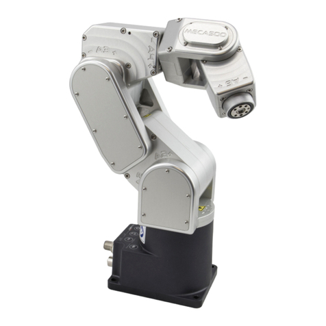
Mecademic Meca500 (R3) Owner's manual

Programming Manual
Meca500 (R3)
Robot Firmware: 8.4
Document Revision: A
July 20, 2021

The information contained herein is the property of Mecademic Inc. and shall not be
reproduced in whole or in part without prior written approval of Mecademic Inc. The
information herein is subject to change without notice and should not be construed as a
commitment by Mecademic Inc. This manual will be periodically reviewed and revised.
Make sure that the rmware of your robot is the one indicated on the cover of this
manual, or else consult the manual corresponding to your robot’s rmware. Ideally,
always use the latest robot rmware. Manuals and rmware updates are available at
https://www.mecademic.com/en/downloads.
If you have a technical question, please visit our Support Center and create a ticket at
https://support.mecademic.com.
Mecademic Inc. assumes no responsibility for any errors or omissions in this document.
Copyright c
○
2021 by Mecademic Inc.

Contents
1 Basic theory and denitions 1
1.1 Denitions and conventions
......................... 1
1.1.1 Units.................................... 1
1.1.2 Jointnumbering.............................. 1
1.1.3 Referenceframes ............................. 1
1.1.4 Pose and Euler angles . . . . . . . . . . . . . . . . . . . . . . . . . . 2
1.1.5 Joint angles and joint 6 turn conguration . . . . . . . . . . . . . . . 3
1.1.6 Joint set and robot posture . . . . . . . . . . . . . . . . . . . . . . . 4
1.2 Congurations, singularities and workspace
............... 4
1.2.1 Inverse kinematic solutions and conguration parameters . . . . . . . 4
1.2.2 Automatic conguration selection . . . . . . . . . . . . . . . . . . . . 7
1.2.3 Workspace and singularities . . . . . . . . . . . . . . . . . . . . . . . 9
1.3 Key concepts related to Mecademic robots
............... 10
1.3.1 Homing .................................. 10
1.3.2 Blending.................................. 11
1.3.3 Position and velocity modes . . . . . . . . . . . . . . . . . . . . . . . 12
2 Communicating over TCP/IP 15
2.1 Motion commands
............................... 15
2.1.1 Delay(
𝑡
).................................. 16
2.1.2 GripperOpen/GripperClose . . . . . . . . . . . . . . . . . . . . . . . 16
2.1.3 MoveJoints(
𝜃1, 𝜃2, 𝜃3, 𝜃4, 𝜃5, 𝜃6
)...................... 17
2.1.4 MoveJointsVel(
˙
𝜃1,˙
𝜃2,˙
𝜃3,˙
𝜃4,˙
𝜃5,˙
𝜃6
) .................... 17
2.1.5 MoveLin(
𝑥, 𝑦, 𝑧, 𝛼, 𝛽, 𝛾
).......................... 18
2.1.6 MoveLinRelTRF(
𝑥, 𝑦, 𝑧, 𝛼, 𝛽, 𝛾
) ..................... 19
2.1.7 MoveLinRelWRF(
𝑥, 𝑦, 𝑧, 𝛼, 𝛽, 𝛾
)..................... 19
2.1.8 MoveLinVelTRF(
˙𝑥, ˙𝑦, ˙𝑧, 𝜔𝑥, 𝜔𝑦, 𝜔𝑧
).................... 20
2.1.9 MoveLinVelWRF(
˙𝑥, ˙𝑦, ˙𝑧, 𝜔𝑥, 𝜔𝑦, 𝜔𝑧
) ................... 20
2.1.10 MovePose(
𝑥, 𝑦, 𝑧, 𝛼, 𝛽, 𝛾
)......................... 21
2.1.11 SetAutoConf(
𝑒
).............................. 21
2.1.12 SetAutoConfTurn(
𝑒
) ........................... 22
2.1.13 SetBlending(
𝑝
) .............................. 22
2.1.14 SetCartAcc(
𝑝
)............................... 23
2.1.15 SetCartAngVel(
𝜔
) ............................ 23
2.1.16 SetCartLinVel(
𝑣
) ............................. 24
2.1.17 SetCheckpoint(
𝑛
)............................. 24
i

2.1.18 SetConf(
𝑐𝑠, 𝑐𝑒, 𝑐𝑤
)............................. 24
2.1.19 SetConfTurn(
𝑐𝑡
).............................. 25
2.1.20 SetGripperForce(
𝑝
)............................ 25
2.1.21 SetGripperVel(
𝑝
) ............................. 26
2.1.22 SetJointAcc(
𝑝
) .............................. 26
2.1.23 SetJointVel(
𝑝
)............................... 26
2.1.24 SetTorqueLimits(
𝑝1, 𝑝2, 𝑝3, 𝑝4, 𝑝5, 𝑝6
)................... 27
2.1.25 SetTorqueLimitsCfg(
𝑠, 𝑚
) ........................ 27
2.1.26 SetTRF(
𝑥, 𝑦, 𝑧, 𝛼, 𝛽, 𝛾
).......................... 28
2.1.27 SetVelTimeout(
𝑡
)............................. 28
2.1.28 SetWRF(
𝑥, 𝑦, 𝑧, 𝛼, 𝛽, 𝛾
).......................... 28
2.2 Request commands of general type
.................... 29
2.2.1 ActivateRobot............................... 29
2.2.2 ActivateSim/DeactivateSim . . . . . . . . . . . . . . . . . . . . . . . 29
2.2.3 ClearMotion................................ 29
2.2.4 DeactivateRobot ............................. 30
2.2.5 BrakesOn/BrakesO . . . . . . . . . . . . . . . . . . . . . . . . . . . 30
2.2.6 EnableEtherNetIP(
𝑒
)........................... 30
2.2.7 GetFwVersion............................... 30
2.2.8 GetModelJointLimits(
𝑛
)......................... 31
2.2.9 GetProductType ............................. 31
2.2.10GetRobotSerial .............................. 31
2.2.11Home ................................... 31
2.2.12 LogTrace(
𝑠
)................................ 32
2.2.13PauseMotion ............................... 32
2.2.14ResetError................................. 33
2.2.15ResetPStop ................................ 33
2.2.16ResumeMotion .............................. 33
2.2.17 SetEOB(
𝑒
)................................. 34
2.2.18 SetEOM(
𝑒
) ................................ 34
2.2.19 SetJointLimits(
𝑛
,
𝜃𝑛,𝑚𝑖𝑛
,
𝜃𝑛,𝑚𝑎𝑥
)..................... 34
2.2.20 SetJointLimitsCfg(
𝑒
)........................... 35
2.2.21 SetMonitoringInterval(
𝑡
)......................... 35
2.2.22 SetNetworkOptions(
𝑛1, 𝑛2, 𝑛3, 𝑛4, 𝑛5, 𝑛6
) ................ 36
2.2.23 SetOineProgramLoop(
𝑒
)........................ 36
2.2.24 SetRTC(
𝑡
)................................. 36
2.2.25 StartProgram(
𝑛
) ............................. 37
ii

2.2.26 StartSaving(
𝑛
) .............................. 37
2.2.27StopSaving ................................ 38
2.2.28 SwitchToEtherCAT . . . . . . . . . . . . . . . . . . . . . . . . . . . . 38
2.2.29 TCPDump(
𝑛
)............................... 39
2.2.30TCPDumpStop.............................. 39
2.3 Request commands of type user-dened data
.............. 39
2.3.1 GetAutoConf ............................... 39
2.3.2 GetAutoConfTurn ............................ 40
2.3.3 GetBlending................................ 40
2.3.4 GetCartAcc................................ 40
2.3.5 GetCartAngVel.............................. 40
2.3.6 GetCartLinVel............................... 40
2.3.7 GetCheckpoint .............................. 41
2.3.8 GetConf.................................. 41
2.3.9 GetConfTurn ............................... 41
2.3.10GetGripperForce ............................. 42
2.3.11GetGripperVel .............................. 42
2.3.12GetJointAcc................................ 42
2.3.13 GetJointLimits(
𝑛
) ............................ 42
2.3.14GetJointLimitsCfg ............................ 43
2.3.15GetJointVel................................ 43
2.3.16 GetMonitoringInterval . . . . . . . . . . . . . . . . . . . . . . . . . . 43
2.3.17 GetNetworkOptions . . . . . . . . . . . . . . . . . . . . . . . . . . . . 43
2.3.18 GetRealTimeMonitoring . . . . . . . . . . . . . . . . . . . . . . . . . 43
2.3.19GetTorqueLimits ............................. 44
2.3.20 GetTorqueLimitsCfg . . . . . . . . . . . . . . . . . . . . . . . . . . . 44
2.3.21GetTRF.................................. 44
2.3.22GetVelTimeout .............................. 44
2.3.23GetWRF.................................. 45
2.4 Request commands of type real-time data
................ 45
2.4.1 GetCmdPendingCount . . . . . . . . . . . . . . . . . . . . . . . . . . 46
2.4.2 GetJoints ................................. 46
2.4.3 GetPose .................................. 46
2.4.4 GetRtAccelerometer(
𝑛
).......................... 47
2.4.5 GetRTC.................................. 47
2.4.6 GetRtCartPos............................... 47
2.4.7 GetRtCartVel............................... 48
iii

2.4.8 GetRtConf................................. 48
2.4.9 GetRtConfTurn.............................. 49
2.4.10GetRtJointPos .............................. 49
2.4.11GetRtJointTorq.............................. 49
2.4.12GetRtJointVel............................... 50
2.4.13 GetRtTargetCartPos . . . . . . . . . . . . . . . . . . . . . . . . . . . 50
2.4.14 GetRtTargetCartVel . . . . . . . . . . . . . . . . . . . . . . . . . . . 50
2.4.15GetRtTargetConf............................. 50
2.4.16 GetRtTargetConfTurn . . . . . . . . . . . . . . . . . . . . . . . . . . 51
2.4.17 GetRtTargetJointPos . . . . . . . . . . . . . . . . . . . . . . . . . . . 51
2.4.18 GetRtTargetJointVel . . . . . . . . . . . . . . . . . . . . . . . . . . . 51
2.4.19GetStatusGripper............................. 52
2.4.20GetStatusRobot.............................. 52
2.4.21 GetTorqueLimitsStatus . . . . . . . . . . . . . . . . . . . . . . . . . . 52
2.4.22 SetRealTimeMonitoring(
𝑛1, 𝑛2, ...
).................... 53
2.5 Responses and messages
........................... 54
2.5.1 Command error messages . . . . . . . . . . . . . . . . . . . . . . . . 54
2.5.2 Commandresponses ........................... 56
2.5.3 Statusmessages.............................. 59
2.5.4 Messages over the monitoring port . . . . . . . . . . . . . . . . . . . 60
3 Communicating over cyclic protocols 63
3.1 Overview
..................................... 63
3.1.1 Cyclicdata ................................ 63
3.2 Types of robot commands
.......................... 63
3.2.1 Status change commands . . . . . . . . . . . . . . . . . . . . . . . . . 63
3.2.2 Triggeredactions ............................. 63
3.2.3 Motioncommands ............................ 64
3.3 Sending motion commands to the robot
................. 64
3.3.1 CommandID ............................... 64
3.3.2 MoveIDandSetPoint........................... 64
3.3.3 Adding non-cyclic motion commands to the motion queue (position
mode) ................................... 65
3.3.4 Sending cyclic motion commands (velocity mode) . . . . . . . . . . . 66
3.4 Cyclic data that can be sent to the robot
................ 66
3.4.1 Robotcontrol............................... 66
3.4.2 Motioncontrol .............................. 67
3.4.3 Motionparameters ............................ 67
iv
3.5 Cyclic data received from the robot
.................... 69
4 Communicating over EtherCAT 73
4.1 Overview
..................................... 73
4.1.1 Connectiontypes............................. 73
4.1.2 ESIle................................... 73
4.1.3 EnablingEtherCAT ........................... 73
4.1.4 LEDs ................................... 74
4.2 Object dictionary
............................... 74
4.2.1 Robotcontrol............................... 75
4.2.2 Motioncontrol .............................. 75
4.2.3 Movement................................. 75
4.2.4 Robotstatus ............................... 76
4.2.5 Motionstatus............................... 76
4.2.6 Gripperstatus............................... 77
4.2.7 Jointset.................................. 77
4.2.8 End-eectorpose............................. 78
4.2.9 Conguration ............................... 78
4.2.10Jointvelocities .............................. 79
4.2.11Torqueratios ............................... 79
4.2.12Accelerometer............................... 79
4.2.13 Communication mode (SDO) . . . . . . . . . . . . . . . . . . . . . . 80
4.2.14Brakes(SDO)............................... 80
4.3 PDO mapping
.................................. 81
5 Communicating over EtherNet/IP 83
5.1 Overview
..................................... 83
5.1.1 Connectiontypes............................. 83
5.1.2 EDSle .................................. 83
5.1.3 Forward open exclusivity . . . . . . . . . . . . . . . . . . . . . . . . . 83
5.1.4 Enabling EtherNet/IP . . . . . . . . . . . . . . . . . . . . . . . . . . 83
5.2 Output Tag Assembly
............................. 84
5.2.1 Robotcontroltag............................. 84
5.2.2 MoveIDtag ................................ 85
5.2.3 Motioncontroltag ............................ 85
5.2.4 Motion command group of tags . . . . . . . . . . . . . . . . . . . . . 85
5.2.5 Hosttimetag............................... 86
5.2.6 Brakescontroltag ............................ 86
v

5.3 Input Tag Assembly
.............................. 87
5.3.1 Robotstatustag ............................. 88
5.3.2 Errorcodetag............................... 88
5.3.3 Checkpointtag .............................. 89
5.3.4 MoveIDtag ................................ 89
5.3.5 FIFOspacetag.............................. 89
5.3.6 Motionstatustag............................. 89
5.3.7 OineprogramID ............................ 90
5.3.8 Jointset.................................. 90
5.3.9 End-eectorpose............................. 90
5.3.10Jointvelocities .............................. 91
5.3.11 Joint torque ratios . . . . . . . . . . . . . . . . . . . . . . . . . . . . 91
5.3.12Accelerometer............................... 91
5.3.13 Gripper status tag . . . . . . . . . . . . . . . . . . . . . . . . . . . . 92
5.3.14Conguration ............................... 92
5.3.15Reservedbytes .............................. 92
vi

About this manual
This programming manual describes the key theoretical concepts related to industrial robots
and the three methods that can be used for communicating with our robots from an Ethernet-
enabled computing device (IPC, PLC, PC, Mac, Raspberry Pi, etc.): using either TCP/IP,
EtherCAT or EtherNet/IP protocols. To maximize exibility, instead of oering a propri-
etary robot programming language, we provide a set of robot-related instructions. You can
therefore use any modern programming language that can run on your computing device.
In addition, we currently oer two packages, one for ROS and another for Python, and we’ll
soon add a C
++
API on our GitHub account.
The default communication method used by our robots is over TCP/IP and consists of a
set of text-based motion and request commands to be sent to one of our robots, as well as
a set of text messages sent back by the robot. Therefore, in the following chapter, we will
refer to some of these motion commands in explaining the key theoretical concepts related
to industrial robots. Furthermore, the communication methods based on the EtherCAT
protocol and the EtherNet/IP protocols and described in Chapters 4 and 5, respectively,
are essentially translations of our TCP/IP method. Thus, in these two chapters, we do not
describe again each concept but simply refer to Chapter 2.
In other words, even if you intend to use EtherCAT or EtherNet/IP only, you must read
every single page of this manual. However, before reading this programming manual, you
must rst read the User Manual for Meca500 R3 (FW8.4), available on our web site.
vii


1 Basic theory and denitions
At Mecademic, we are particularly attentive to and concerned about technical accuracy, de-
tail, and consistency, and use terminology that is not always standard. You must, therefore,
read this section very carefully, even if you have prior experience with robot arms.
1.1 Denitions and conventions
1.1.1 Units
Distances that are displayed to or given by the user are in millimeters (mm), angles are in
degrees (
∘
) and time is in seconds (s), except for the timestamps.
1.1.2 Joint numbering
The joints of the Meca500 are numbered in ascending order, starting from the base (Fig. 1a).
(a) robot with all joints at zero degrees
Flange
(b) robot’s ange with joint 6 at zero degrees
Figure 1: (a) Joint numbering and reference frames for the Meca500 and (b) its ange
1.1.3 Reference frames
At Mecademic, we use right-handed Cartesian coordinate systems (
reference frames
). The
reference frames (according to the original Denavit and Hartenberg convention) that we use
are shown in Fig. 1a, but you only need to be familiar with four of them. (The
𝑥
axes are
in red, the
𝑦
axes are in green, and the
𝑧
axes are in blue.) These four reference frames and
the key terms related to them are:
Page 1 of 92

1 Basic theory and denitions
∙
BRF
:
base reference frame
. Static reference frame xed to the robot base. Its
𝑧
axis
coincides with the axis of joint 1 and points upwards, its origin lies on the bottom of
the robot base, and its
𝑥
axis is normal to the base front edge and points forward.
∙
WRF
:
world reference frame
. The main static reference frame. By default, it coincides
with the BRF. It can be dened with respect to the BRF with the SetWRF command.
∙
FRF
:
ange reference frame
. Mobile reference frame xed to the robot’s
ange
(Fig. 1b). Its
𝑧
axis coincides with the axis of joint 6, and points outwards. Its
origin lies on the surface of the robot’s ange. Finally, when all joints are at zero, the
𝑦
axis of the FRF has the same direction as the
𝑦
axis of the BRF.
∙
TRF
:
tool reference frame
. The mobile reference frame associated with the robot’s
end-eector
. By default, the TRF coincides with the FRF. It can be dened with
respect to the FRF with the SetTRF command.
∙
TCP
:
tool center point
. Origin of the TRF. (Not to be confused with the Transmission
Control Protocol acronym, which is also used in this document.)
1.1.4 Pose and Euler angles
Some of Meca500’s commands take a
pose
(position and orientation of one reference frame
with respect to another) as an input. In these commands, and in Meca500’s web interface, a
pose consists of a Cartesian position,
{𝑥
,
𝑦
,
𝑧}
, and an orientation specied in
Euler angles
,
{𝛼, 𝛽, 𝛾}
, according to the mobile XYZ convention (also referred to as R
𝑥
R
𝑦
R
𝑧
). In this
convention, if the orientation of a frame
𝐹1
with respect to a frame
𝐹0
is described by the
Euler angles
{𝛼, 𝛽, 𝛾}
, it means that if you align a frame
𝐹𝑚
with frame
𝐹0
, then rotate
𝐹𝑚
about its
𝑥
axis by
𝛼
degrees, then about its
𝑦
axis by
𝛽
degrees, and nally about its
𝑧
axis
by
𝛾
degrees, the nal orientation of frame
𝐹𝑚
will be the same as that of frame
𝐹1
.
An example of specifying orientation using the mobile XYZ Euler angle convention is
shown in Fig. 2. In the third image of this gure, the orientation of the black reference frame
with respect to the gray reference frame is represented with the Euler angles
{45∘,−60∘,90∘}
.
It is crucial to understand that there are innitely many Euler angles that correspond to
a given orientation. For your convenience, the various motion commands that take a pose
as arguments accept any numerical values for the three Euler angles (e.g., the set {
378.34∘
,
−567.32∘
,
745.03∘
}). However, we output only the equivalent Euler angle set
{𝛼, 𝛽, 𝛾}
, for
which
−180∘≤𝛼≤180∘
,
−90∘≤𝛽≤90∘
and
−180∘≤𝛾≤180∘
. Furthermore, if you
specify the Euler angles
{𝛼, ±90∘, 𝛾}
, the controller will always return an equivalent Euler
angles set in which
𝛼= 0
. Thus, it is perfectly normal that the Euler angles that you have
used to specify an orientation are not the same as the Euler angles returned by the controller,
once that orientation has been attained (see our tutorial on Euler angles, on our web site).
Page 2 of 92

1.1 Denitions and conventions
(a) rotate
45∘
about the
𝑥
axis (b) rotate
−60∘
about the new
𝑦
axis (c) rotate
90∘
about the new
𝑧
axis
Figure 2: The three consecutive rotations associated with the Euler angles
{45∘,−60∘,90∘}
Finally, as we will see in Section 1.2.1, note that the pose of the end-eector alone does
not dene unequivocally the required joint angles.
1.1.5 Joint angles and joint 6 turn conguration
The angle associated with joint
𝑖
(
𝑖= 1,2, ..., 6
),
𝜃𝑖
, will be referred to as
joint angle
𝑖
. Since
joint 6 can rotate more than one revolution, you should think of a joint angle as a motor
angle, rather than as the angle between two consecutive robot links.
A joint angle is measured about the
𝑧
axis associated with the given joint using the right-
hand rule. Note that the direction of rotation for each joint is engraved on the robot’s body.
All joint angles are zero in the robot shown in Fig. 1a. Note, however, that unless you attach
an end-eector with cabling to the robot’s ange, there is no way of telling the value of
𝜃6
just by observing the robot. For example, in Fig. 1b,
𝜃6
might as well be equal to
360∘
.
The mechanical limits of the rst ve robot joints are as follows:
−175∘≤𝜃1≤175∘,
−70∘≤𝜃2≤90∘,
−135∘≤𝜃3≤70∘,
−170∘≤𝜃4≤170∘,
−115∘≤𝜃5≤115∘.
Joint 6 has no mechanical limits, but its software limits are
±
100 turns. Finally, let us dene
the integer
𝑐𝑡
as the axis 6
turn conguration
, such that
−180∘+𝑐𝑡360∘< 𝜃6≤180∘+𝑐𝑡360∘
.
Note that you can further constrain the joint limits with the command SetJointLimits.
Page 3 of 92

1 Basic theory and denitions
1.1.6 Joint set and robot posture
As we will explain later, for a desired location of the robot end-eector with respect to
the robot base, there are several possible solutions for the values of the joint angles, i.e.,
several possible sets
{𝜃1, 𝜃2, 𝜃3, 𝜃4, 𝜃5, 𝜃6}
. Thus, the simplest way to describe how the robot
is postured, is by giving its set of joint angles. We will refer to this set at the
joint set
, and
occasionally as
joint position
.
For example, in Fig. 1a, the joint set is
{0∘,0∘,0∘,0∘,0∘,0∘}
, although, it could have been
{0∘,0∘,0∘,0∘,0∘,360∘}
, and you wouldn’t be able to tell the dierence from the outside.
A joint set denes completely the relative poses, i.e., the “arrangement,” of the seven robot
links (a six-axis robot arm is typically composed of a series of seven links, starting with the
base and ending with the end-eector). We will call this arrangement the
robot posture
. Thus,
the joint sets
{𝜃1, 𝜃2, 𝜃3, 𝜃4, 𝜃5, 𝜃6}
and
{𝜃1, 𝜃2, 𝜃3, 𝜃4, 𝜃5, 𝜃6+𝑐𝑡360∘}
, where
−180∘< 𝜃6≤180∘
and
𝑐𝑡
is the axis 6 turn conguration, correspond to the same robot posture. Therefore, a
joint set has the same information as a robot posture AND an axis 6 turn conguration.
1.2 Congurations, singularities and workspace
1.2.1 Inverse kinematic solutions and conguration parameters
Like virtually all six-axis industrial robot arms available on the market, Meca500’s inverse
kinematics generally provide up to eight feasible robot postures for a desired pose of the TRF
with respect to the WRF (Fig. 3), and many more joint sets (since if
𝜃6
is a solution, then
𝜃6±𝑛360∘
, where
𝑛
is an integer, is also a solution). Each of these solutions is associated
with one of eight
robot posture congurations
, dened by three parameters:
𝑐𝑠
,
𝑐𝑒
and
𝑐𝑤
.
Each of these parameters corresponds to a specic geometric condition on the robot posture:
–
𝑐𝑠
(shoulder conguration parameter):
∙𝑐𝑠= 1
, if the
wrist center
(where the axes of joints 4, 5 and 6 intersect) is on the
“front” side of the plane passing through the axes of joints 1 and 2 (see Fig. 4a).
The condition
𝑐𝑠= 1
is often referred to as “front”.
∙𝑐𝑠=−1
, if the wrist center is on the “back” side of this plane (see Fig. 4c).
–
𝑐𝑒
(elbow conguration parameter):
∙𝑐𝑒= 1
, if
𝜃3>−arctan(60/19) ≈ −72.43∘
(“elbow up” condition, see Fig. 4d);
∙𝑐𝑒=−1
, if
𝜃3<−arctan(60/19) ≈ −72.43∘
(“elbow down” condition, see Fig. 4f).
–
𝑐𝑤
(wrist conguration parameter):
∙𝑐𝑤= 1
, if
𝜃5>0∘
(“no ip” condition, see Fig. 4g);
∙𝑐𝑤=−1
, if
𝜃5<0∘
(“ip” condition, see Fig. 4i).
Page 4 of 92

1.2 Congurations, singularities and workspace
(a)
{1,1,1}
(b)
{1,1,−1}
(c)
{1,−1,1}
(d)
{1,−1,−1}
(e)
{−1,1,1}
(f)
{−1,1,−1}
(g)
{−1,−1,1}
(h)
{−1,−1,−1}
Figure 3: An example showing all eight possible robot postures, described by the robot
posture conguration parameters
{𝑐𝑠, 𝑐𝑒, 𝑐𝑤}
, for the pose
{
77 mm, 210 mm, 300 mm,
−103∘
,
36∘
,
175∘}
of the FRF with respect to the BRF
Figure 4 shows an example of each robot posture conguration parameter, as well as of
the limit conditions, which are called
singularities
. Note that the popular terms front/back
and elbow-up/elbow-down are misleading as they are not relative to the robot base but to
specic planes that move when some of the robot joints rotate.
When we solve the inverse kinematics, we select the solution that corresponds to your
desired robot posture conguration,
{𝑐𝑠, 𝑐𝑒, 𝑐𝑤}
, dened by the command SetConf, but we
also have to select the value for
𝜃6
that corresponds to your desired turn conguration,
𝑐𝑡
(an integer in the range
±100
), dened by the command SetConfTurn. The turn is therefore
the last inverse kinematics conguration parameter.
Both the turn conguration and the set of robot posture conguration parameters are
needed to pinpoint the solution to the robot inverse kinematics, i.e., to pinpoint the joint
set corresponding to the desired pose. However, there are major dierences between the
Page 5 of 92

1 Basic theory and denitions
(a)
𝑐𝑠= 1
, front (b) shoulder singularity (c)
𝑐𝑠=−1
, back
(d)
𝑐𝑒= 1
, elbow down (e) elbow singularity (f)
𝑐𝑒=−1
, elbow down
(g)
𝑐𝑤= 1
, noip (h) wrist singularity (i)
𝑐𝑤=−1
, ip
Figure 4: Inverse kinematic conguration parameters and the three types of singularities
turn and robot posture conguration parameters, the main being the fact that the change
of turn does not involve singularities. This is why we use dierent commands (SetConf and
SetConfTurn, SetAutoConf and SetAutoConfTurn, etc.).
Page 6 of 92

1.2 Congurations, singularities and workspace
While we do oer you the possibility of calculating the optimal inverse kinematic solution
(commands SetAutoConf and SetAutoConfTurn), we highly recommend that you always
specify the desired values for the congurations parameters (with the commands SetConf
and SetConfTurn) for every Cartesian-coordinates motion command (i.e., MovePose and the
various MoveLin* commands), at least when programming your robot in
online mode
.
Thus, if you are teaching the
robot position
and want that later its end-eector moves to
the current pose along a linear path, you need to record not only the current pose of the TRF
w.r.t. the WRF (by retrieving it with GetRtCartPos), but also the denitions of the TRF
and the WRF (with GetTRF and GetWRF), and nally the corresponding conguration
parameters (with GetRtConf and GetRtConfTurn). Then, when you later want to approach
this robot position with MoveLin from a starting robot position, you need to make sure the
robot is already in the same robot posture conguration and that
𝜃6
is no more than half
a revolution away from the desired value. If, however, you do not need the robot’s TCP
to follow a linear trajectory, then you should better get the current joint values only (using
GetRtJointPos) and later go to that robot position using the command MoveJoints, thus
not having to record and then specify the conguration parameters.
1.2.2 Automatic conguration selection
Using the automatic conguration selection should only be used once you understand how
this selection is done, and mainly in
o-line mode
. In other words, the automatic congu-
ration selection should be enabled only if the desired pose of the TRF with respect to the
WRF (commands MovePose or MoveLin) or with respect to the current pose of the TRF
(commands MoveLinRelTRF and MoveLinRelWRF) was calculated.
Figure 5 illustrates how the automatic and manual conguration selections work. Firstly
(see notes 1 and 2), setting a desired robot posture conguration (SetConf) disables the au-
tomatic robot posture conguration selection, which is set by default. Inversely, enabling the
automatic robot posture conguration selection, with SetAutoConf(1), removes the desired
robot posture conguration, if such was set. Similarly, setting a desired turn conguration
(SetConfTurn) disables the automatic turn conguration selection. Inversely, enabling the
automatic turn conguration selection, with SetAutoConfTurn(1), removes the desired turn
conguration, if such was set.
Secondly (see notes 3 and 4), even if you have set desired conguration parameters
or enabled the automatic conguration selection, you can always use the MoveJoints and
MoveJointsVel commands and these may override your choice. Indeed, once you have moved
the robot with any of these two commands, the desired robot posture conguration is auto-
matically set to the one corresponding to the resulting robot position. Similarly, the desired
Page 7 of 92

1 Basic theory and denitions
SetConf
3
MoveLin6
MoveLinRelTRF6
MoveLinRelWRF6
MoveLinVelTRF6
MoveLinVelWRF6
MovePose5
SetAutoConf
SetConfTurn
SetAutoConfTurn
MoveJoints
MoveJointsVel
4
1
2
Notes:
1. SetConf(
cs
,
ce
,
cw
) disables the AutoConf setting, while SetAutoConf(1) disables the desired robot posture configuration setting.
2. SetConfTurn(
ct
) disables the AutoConfTurn setting, while SetAutoConfTurn(1) disables the desired turn setting.
3. Both MoveJoints and MoveJointsVel update the desired robot posture configuration with the one corresponding to the robot
position after the execution of any of these two commands, unless AutoConf was already on.
4. Both MoveJoints and MoveJointsVel update the desired turn configuration with the one corresponding to the value of θ6after
the execution of any of these two commands, unless AutoConfTurn was already on.
5. Joint 6 (or even joints 1 and 4) can rotate more than 180° with a single MovePose command.
6. No joint can rotate more than 180° with a single MoveLin* command, so SetConfTurn is only validated.
Figure 5: The relationship between the inverse kinematics conguration parameters and the
dierent motion commands
turn conguration is automatically set to the one corresponding to the resulting robot posi-
tion, but only if automatic turn selection was not enabled.
Enabling automatic robot posture conguration selection or specifying a desired robot
posture conguration has eect only on the command MovePose. Indeed, the robot cannot
change its robot posture conguration during a MoveLin*, since it cannot cross a singularity.
An automatic robot posture conguration selection allows the robot controller to select the
robot position (among many possible), corresponding to the desired pose, that is fastest to
reach. In contrast, the selection of the turn conguration has eect on both the MovePose
and MoveLin* commands. If automatic turn selection is enabled, the robot will always rotate
joint 6 at most
180∘
.
Note that it could be perfectly logical to set a desired robot posture conguration, but
enable the automatic turn conguration. For example, if your end-eector is Schunk’s Adheso
cableless gripping system, there is no reason to prefer one turn over another (e.g., to prefer
𝜃6= 17∘
over
𝜃6= 377∘
).
Page 8 of 92

1.2 Congurations, singularities and workspace
Finally, there is no limit on the required joint rotations (note 5 in Fig. 5) when using
the MovePose command (as long as these rotations are withing the joint limits, of course).
In contrast, no joint can rotate more than
180∘
with a single MoveLin* command (note 6).
Thus, specifying the desired turn conguration does not does guarantee that the robot will
execute the motion command. For example, if
𝜃6=−1∘
in the starting robot position, then
you sent the command SetTurn(1), and then the command MoveLin, the robot will report
an error, whatever the desired pose, because joint 6 would have to rotate more than
180∘
,
which, while physically possible, has been disabled by us.
1.2.3 Workspace and singularities
Many users mistakenly oversimplify the workspace of a six-axis robot arm as a sphere of
radius equal to the
reach
of the robot (the maximum distance between the axis of joint 1
and the center of the robot’s wrist). The truth is that the Cartesian
workspace
of a six-axis
industrial robot is a six-dimensional entity: the set of all attainable end-effector poses (see
our tutorial on workspace, available on our web site). Therefore, the workspace of a robot
depends on the choice of TRF. Worse yet, as we saw in the preceding section, for a given
end-eector pose, we can generally have eight dierent robot postures (Fig. 3). Thus, the
Cartesian workspace of a six-axis robot arm is the combination of eight workspace subsets,
one for each the eight robot posture congurations. These eight workspace subsets have
common parts, but there are also parts that belong to only one subset (i.e, there are end-
eector poses accessible with only one conguration, because of joint limits). Therefore, in
order to make optimal use of all attainable end-eector poses, the robot must often pass from
one subset to the other. These passages involve so-called
singularities
and are problematic
when the robot’s end-eector is to follow a specic Cartesian path.
Any six-axis industrial robot arm has singularities (see our tutorial on singularities, avail-
able on our web site). However, the advantage of robot arms like the Meca500, where the
axes of the last three joints intersect at one point (the center of the robot’s wrist), is that
these singularities are very easy to describe geometrically (see Fig. 4). In other words, it is
very easy to know whether a robot posture is close to singularity in the case of the Meca500.
In a singular robot posture, some of the joint set solutions corresponding to the pose
of the TRF may coincide, or there may be innitely many joint sets. The problem with
singularities is that at a singular robot posture, the robot’s end-eector cannot move in
certain directions. This is a physical blockage, not a controller problem. Thus, singularities
are one type of workspace boundary (the other type occurs when a joint is at its limit, or
when two links interfere mechanically).
Page 9 of 92

1 Basic theory and denitions
For example, consider the Meca500 at its zero robot posture (Fig. 1a). At this robot pos-
ture, the end-eector cannot be moved laterally (i.e., parallel to the
𝑦
axis of the BRF); it is
physically blocked. Thus, singularities are not some kind of purely mathematical problem.
They represent actual physical limits. That said, because of the way a robot controller is
programmed, at a singular robot posture (or at a robot posture that is very close to a singu-
larity), the robot cannot be moved in any direction using a Cartesian-space motion command
(MoveLin, MoveLinRelTRF, MoveLinRelWRF, MoveLinVelTRF, or MoveLinVelWRF).
There are three types of singular robots positions, and these correspond to the conditions
under which the conguration parameters
𝑐1
,
𝑐3
and
𝑐5
are not dened. The most common
singular robot posture is called
wrist singularity
and occurs when
𝜃5= 0∘
(Fig. 4h). In
this singularity, joints 4 and 6 can rotate in opposite directions at equal velocities while
the end-eector remains stationary. You will run into this singularity very frequently. The
second type of singularity is called
elbow singularity
(Fig. 4e). It occurs when the arm is
fully stretched, i.e., when the wrist center is in one plane with the axes of joints 2 and 3. In
the Meca500, this singularity occurs when
𝜃3=−arctan(60/19) ≈ −72.43∘
. You will run
into this singularity when you try to reach poses that are too far from the robot base. The
third type of singularity is called
shoulder singularity
(Fig. 4b). It occurs when the center
of the robot’s wrist lies on the axis of joint 1. You will run into this singularity when you
work too close to the axis of joint 1.
As already mentioned, you can never pass through a singularity using a Cartesian-space
motion command. However, you will have no problem with singularities when using the
command MoveJoints, and to a certain extent, the command MovePose. Finally, you need
to know that when using a Cartesian-space command, problems occur not only when crossing
a singularity, but also when passing too close to a singularity. When passing close to a wrist
or shoulder singularity, some joints will move very fast (i.e., 4 and 6, in the case of a wrist
singularity, and 1, 4 and 6, in the case of a shoulder singularity), even though the TCP
speed is very low. Thus, you must avoid moving in the vicinity of singularities when using
Cartesian-space motion commands.
1.3 Key concepts related to Mecademic robots
1.3.1 Homing
At power-up, the Meca500 knows the approximate angle of each of its joints, with a couple
of degrees of uncertainty. To nd the exact joint angles with high accuracy, each motor must
make one full revolution. This motion is the essential part of a procedure called
homing
.
Page 10 of 92
Table of contents
Other Mecademic Robotics manuals

Mecademic
Mecademic Meca500 User manual

Mecademic
Mecademic Meca500 User manual

Mecademic
Mecademic Meca500 User manual

Mecademic
Mecademic Meca500 User manual

Mecademic
Mecademic Meca500 User manual

Mecademic
Mecademic MEGP 25E User manual

Mecademic
Mecademic Meca500 R3 Owner's manual

Mecademic
Mecademic Meca500 User manual

Mecademic
Mecademic Meca500 R3 User manual

Mecademic
Mecademic Meca500 R3 User manual
Popular Robotics manuals by other brands

Sportcraft
Sportcraft INTREPID 2.0 manual

MIR
MIR 250 Hook user guide

QUICK INTELLIGENT EQUIPMENT
QUICK INTELLIGENT EQUIPMENT ET8383 instruction manual

WEISS ROBOTICS
WEISS ROBOTICS GRIPKIT CR EASY instruction manual

Robotis
Robotis Dynamixel RX-64 user manual

Waveshare
Waveshare AlphaBot2-PiZero Assembly Diagram