DEC VR315 User manual

VR315andVR325MonochromeMonitors
ServiceGuide
Order Number EK-VR315-SV-002
Digital Equipment Corporation

Second Edition, February 1991
The information in this document is subject to change without notice and should not
be construed as a commitment by Digital Equipment Corporation. Digital Equipment
Corporation assumes no responsibility for any errors that may appear in this document.
The software described in this document is furnished under a license and may be used or
copied only in accordance with the terms of such license.
No responsibility is assumed for the use or reliability of software on equipment that is not
supplied by Digital Equipment Corporation or its affiliated companies.
Restricted Rights: Use, duplication, or disclosure by the U. S. Government is subject to
restrictions as set forth in subparagraph (c) (1) (ii) of the Rights in Technical Data and
Computer Software clause at DFARS 252.227–7013.
Copyright © Digital Equipment Corporation 1991
All Rights Reserved.
Printed in U.S.A.
The following are trademarks of Digital Equipment Corporation:
DEC DIBOL UNIBUS
DEC/CMS EduSystem VAX
DEC/MMS IAS VAXcluster
DECnet MASSBUS VMS
DECsystem–10 PDP VT
DECSYSTEM–20 PDT
DECUS RSTS
DECwriter RSX
dt
This document was prepared and published by Educational Services Development and
Publishing, Digital Equipment Corporation.

Contents
About This Manual vii
1 Overview
1.1 Product Description ................................ 1–1
1.1.1 Model Variations ................................ 1–2
1.2 Tools and Equipment ............................... 1–2
1.3 Recommended Spare Parts List ....................... 1–3
2 Troubleshooting
2.1 Before You Start. . . ................................ 2–1
2.2 Troubleshooting Procedures . . ........................ 2–2
2.3 Troubleshooting Tables.............................. 2–2
3 Removing and Replacing FRUs
3.1 Introduction ...................................... 3–1
3.1.1 Removing the External Cables ...................... 3–2
3.1.2 Removing the Rear Cover . ........................ 3–3
3.1.3 Removing the Top Cover . . ........................ 3–4
3.2 Field Replaceable Units (FRUs)....................... 3–5
3.2.1 Interconnect Cable ............................... 3–6
3.2.2 Power Supply Module ............................ 3–8
3.2.3 Discharging the CRT and Removing the Anode Cap ..... 3–10
3.2.4 Deflection Module ............................... 3–12
3.2.5 Video Casting Assembly . . . ........................ 3–16
3.2.6 CRT/Chassis Assembly............................ 3–20
3.3 CRT Disposal (Trained Service Personnel Only) . . . ....... 3–21
3.4 Tilt-Swivel Base . . ................................ 3–24
iii

iv Contents
4 Aligning the Video Monitor
4.1 Introduction ...................................... 4–1
4.1.1 Before You Start. ................................ 4–1
4.1.2 Check LEDs and Heater Filament................... 4–4
4.1.3 Displaying Screen Tests . . . ........................ 4–4
4.2 Monitor Adjustments ............................... 4–5
4.3 Deflection Adjustments ............................. 4–6
4.3.1 Raster Adjustment ............................... 4–6
4.3.2 Anode Voltage Adjustment . ........................ 4–6
4.3.3 Height and Width Adjustments ..................... 4–6
4.4 Using the Radiance Meter . . . ........................ 4–8
4.5 Cutoff Adjustment . ................................ 4–10
4.6 GAIN Adjustment . ................................ 4–11
A VR315 and VR325 Documentation
Figures
1–1 Monochrome Monitor ............................... 1–1
3–1 Removing Cables from the Monitor .................... 3–2
3–2 Rear Cover Removal ............................... 3–3
3–3 Top Cover Removal ................................ 3–4
3–4 Field Replaceable Units ............................. 3–5
3–5 Disconnecting the Interconnect Cable . . . ............... 3–7
3–6 Removing the On/Off Switch Cable from the Power Supply . . 3–8
3–7 Removing the Power Supply . ........................ 3–9
3–8 Discharging the CRT and Removing the Anode Cap ....... 3–11
3–9 Loosening the Captive Screw . ........................ 3–13
3–10 Disconnecting Cables from the Deflection Module . . ....... 3–14
3–11 Removing the Deflection Module ...................... 3–15
3–12 Removing Cables from the Video Casting ............... 3–17
3–13 Removing the CRT Socket Connector ................... 3–18
3–14 Removing the Video Casting . ........................ 3–19
3–15 Crushing the Evacuation Point ....................... 3–23
3–16 Tilt-Swivel Base . . ................................ 3–25
4–1 User Controls and Indicator . . ........................ 4–3

Contents v
4–2 Circle-Crosshatch Pattern . . . ........................ 4–4
4–3 Using the Metric Measuring Tape ..................... 4–5
4–4 Internal Controls . . ................................ 4–7
4–5 Radiance Meter . . . ................................ 4–9
4–6 Using the Radiance Meter . . . ........................ 4–10
4–7 GAIN, G2, and FOCUS (G4) Adjustments .............. 4–11
Tables
1–1 Tools and Equipment ............................... 1–2
1–2 Recommended Spare Parts. . . ........................ 1–3
2–1 Blank Screen, No Video or Raster ..................... 2–3
2–2 Blank Screen, No Video, but Raster is Present ........... 2–5
2–3 Poor Display Quality ............................... 2–6
4–1 Monitor Controls and Indicators ...................... 4–2


AboutThisManual
VR315 and VR325 Video Monitors
This guide describes how to service the VR315 and VR325 monochrome
monitors in the field.
Manual Organization
This manual is organized as follows:
• Chapter 1 provides a general overview of the product and includes a
list of spare parts.
• Chapter 2 describes the troubleshooting procedures.
• Chapter 3 provides the removing and replacing procedures for the
Field Replaceable Units (FRUs).
• Chapter 4 describes the alignment procedures.
• Appendix A describes related documentation.
Conventions
Convention Meaning
Caution Provides information to prevent damage to the equipment.
Warning Provides information that relates to personal safety.
Note Provides general information.
PN Refers to a part number.
!
This type of number in text refers to an item in an illustration.
monitor Refers to the VR315 and VR325 monochrome monitors.
vii


1
Overview
1.1 Product Description
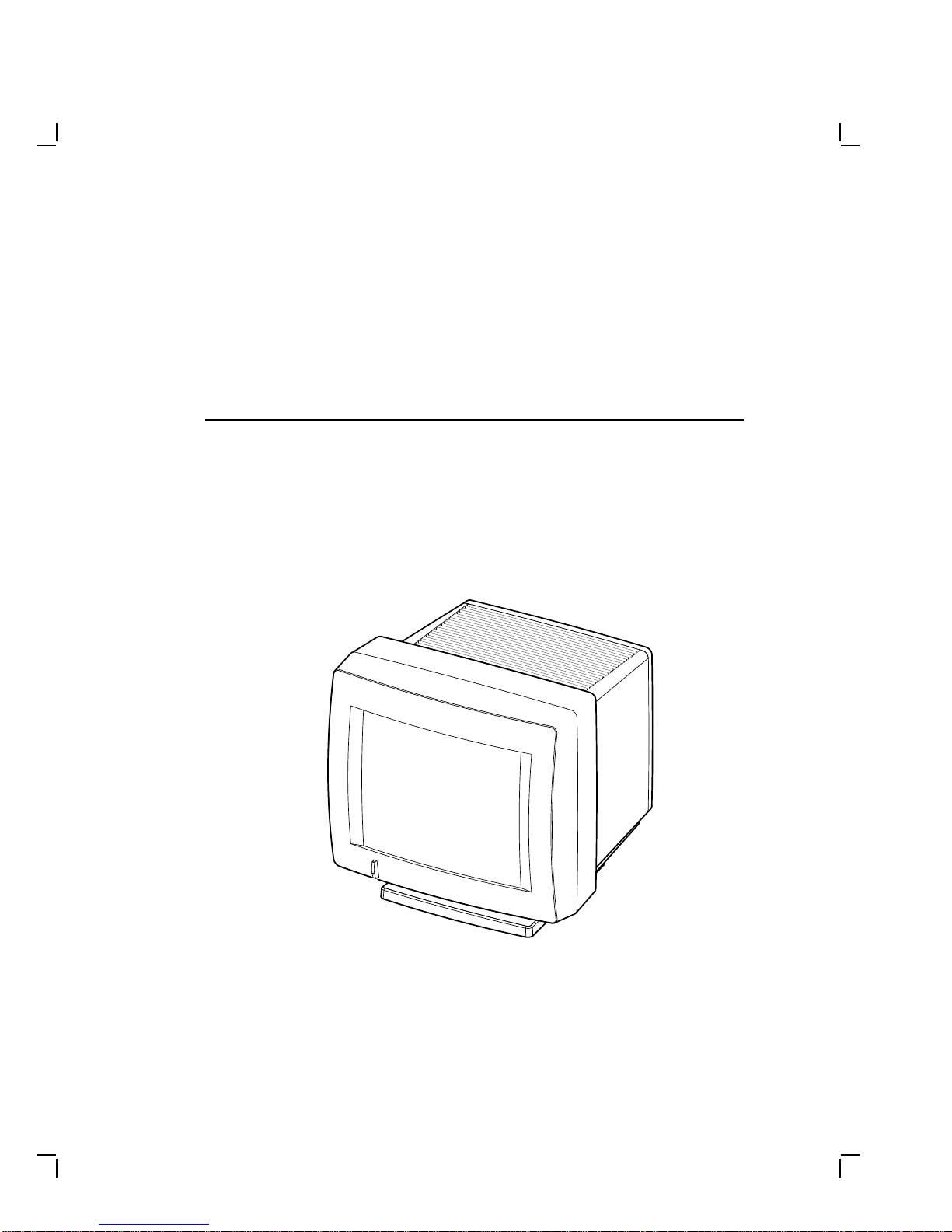
The monochrome monitor (Figure 1–1) has a direct viewed antiglare
screen with an auto-ranging power supply for worldwide operation. Its
built-in tilt-swivel base lets the user adjust the screen for viewing comfort.
When connected to a host system, the monitor displays information sent
by the host.
MA-0299-90.DG
Figure 1–1 Monochrome Monitor
1–1

1–2 Overview
1.1.1 Model Variations
The monitor is available in the following models:
Model Applicable Area
VR315-DA Northern hemisphere
VR315-D4 Southern hemisphere
VR325-DA Northern hemisphere
VR325-D4 Southern hemisphere
1.2 Tools and Equipment
Table 1–1 lists the tools and equipment you will need to service the
monitor:
Table 1–1 Tools and Equipment
Tools and Equipment Part Number
Terminal technician tool kit 29-27340-01
Static protection kit 29-26246-00
Anode discharge tool 29-24717-00
Metric measuring tape 29-25342-00
Safety goggles 29-16141-00
Gloves 29-16146-00

Overview 1–3
1.3 Recommended Spare Parts List
Table 1–2 lists the recommended spare parts for the monitor.
Table 1–2 Recommended Spare Parts
Spare Part VR315 Part
Number VR325 Part
Number
Power supply 54-19629-02 54-19629-03
Deflection module 54-19826-01 54-19826-02
Video casting assembly 70-27073-01 70-27073-01
Module interconnect cable 70-27000-02 70-27000-02
CRT/chassis assembly
Northern Hemisphere 70-27477-01 70-27481-03
Southern Hemisphere 70-27477-02 70-27481-04


2
Troubleshooting
This chapter describes how to troubleshoot a monitor problem through
fault isolation.
2.1 Before You Start
The following information will help you troubleshoot the monitor easily
and effectively:
WARNING
If you smell burning components, press the monitor power switch
off and disconnect the power cord.
• If you are going to service a display quality type of problem, tell the
customer to warm the monitor up for at least 20 minutes, if possible,
before you arrive and begin the troubleshooting procedures.
• Magnetic fields affect monitor performance and can give a false
indication of a monitor failure. Place the monitor away from any
electromagnetic devices such as printers and terminals, or away from
large magnetized objects such as filing cabinets and steel beams in
walls.
NOTE
Any time you replace a video casting assembly, deflection module,
or power supply module, perform all the necessary adjustments.
Refer to Chapter 3.
2–1

2–2 Troubleshooting
2.2 Troubleshooting Procedures
These procedures assume that only one assembly has failed or only one
problem exists. Always troubleshoot the most obvious symptom first;
however, one symptom may indicate multiple failures. Problems may
come from either the host system or the monitor.
Troubleshoot the monitor as follows:
1. Ask the operator to describe the problem. The operator often is the
most knowledgeable.
2. Identify the problem. The screen display often indicates which
problem is occurring.
3. Isolate the problem. Refer to the troubleshooting tables (Section 2.3)
to find the suggested solutions.
4. Display the host system alignment test patterns to make sure that
no other problem exists. Refer to the host system service guide for
displaying test patterns.
2.3 Troubleshooting Tables
The troubleshooting tables list the possible cause in order of probability.
This troubleshooting information applies to three types of video problems
that the monitor may exhibit:
• A blank screen, without video or raster (Table 2–1)
• A blank screen, without video, but raster present (Table 2–2)
• Poor display quality (Table 2–3)
Use the troubleshooting tables as follows:
1. Note the symptom of the problem.
2. Check the Symptom column for a match.
3. Check the conditions in the Possible Cause column in the order given.
4. Perform the action in the Suggested Solution column in the order
given.

Troubleshooting 2–3
Table 2–1 Blank Screen, No Video or Raster
Symptom Possible Cause Suggested Solution
Blank screen, no video
or raster. Power to
the monitor is on (the
power switch is in) but
the power indicator
light is off.
The power cord is
not connected to
the power source or
monitor.
Connect the power cord to the
power source or monitor.
Low or no power at
wall outlet. Use another wall outlet. If
the problem continues, call the
facilities person.
Power supply
module is faulty. Replace the power supply
module (Section 3.2.2).
Deflection module
is faulty. Replace the deflection module
(Section 3.2.4).
Video module is
faulty. Replace the video casting
assembly (Section 3.2.5).
No video or raster, but
the power indicator is
on.
Brightness or
contrast is set
incorrectly.
Adjust the brightness and
contrast controls.
Power to the host
system is not on. Turn power to the host system
on.
Host signal cable is
disconnected. Connect the signal cable to the
monitor and host.

2–4 Troubleshooting
Table 2–1 (Cont.) Blank Screen, No Video or Raster
Symptom Possible Cause Suggested Solution
Deflection module
is faulty. Replace the deflection module
(Section 3.2.4).
Video casting
assembly is faulty. Replace the video casting
assembly (Section 3.2.5).
CRT/chassis
assembly is faulty. Replace the CRT/chassis
assembly (Section 3.2.6)
only after trying the previous
solutions.
No video or raster, but
the power indicator
and LED on the
deflection module are
on.
Internal cabling is
loose or faulty. Check all cabling going to
the deflection module and
the video casting assembly,
including the CRT socket
connector. If necessary, secure
the cables.
G2 Bias is set
incorrectly. Correct the G2 adjustment.
(Section 4.5).
Signal cable is
faulty. Replace the signal cable.
Refer to the host system
documentation.
Deflection module
is faulty. Replace the deflection module
(Section 3.2.4).
No video or raster, but
the power indicator
LED is on; the
deflection module
LED is off.
Deflection module
is faulty. Replace the deflection module
(Section 3.2.4).

Troubleshooting 2–5
Table 2–2 Blank Screen, No Video, but Raster is Present
Symptom Possible Cause Suggested Solution
Raster can be
displayed by
adjusting the
brightness control,
but no video or
cursor can be seen
even when the
contrast control is
at maximum.
The Host system
CRT screen saver
feature is activated.
Press any key to reactivate the
display.
Internal cabling is
loose or faulty. Check all the cables to the
deflection module and the
video casting assembly.
The host system
is not supplying
video signals to the
monitor.
Connect the monitor to a
known working host system (if
available) to verify the problem
before replacing any monitor
modules.
Host system is
faulty. Repair the host system.
Video casting
assembly is faulty. Replace the video casting
assembly (Section 3.2.5).
Deflection module is
faulty. Replace the deflection module
(Section 3.2.4).
Faulty CRT/chassis
assembly Replace the CRT/chassis
assembly (Section 3.2.6)
only after trying the previous
solutions.

2–6 Troubleshooting
NOTE
Make sure the monitor has warmed up for at least 20 minutes
before you use Table 2–3.
Table 2–3 Poor Display Quality
Symptom Possible Cause Suggested Solution
Poor geometry,
centering, height,
width, and/or
linearity.
Controls on top of the
monitor are out of
adjustment.
See section 4.1.
Local magnetic fields. Remove any electro-
mechanical devices from
the vicinity of the monitor, or
move the monitor to another
location.
Monitor is out of
adjustment. Perform the alignment
procedure. Refer to Chapter
4.
Deflection module is
faulty. Replace the deflection module
(Section 3.2.4).
CRT/chassis assembly
is faulty. Replace the CRT/chassis
assembly (Section 3.2.6) only
after trying the previous
solutions.
Poor light output
(using the all-white
diagnostic pattern).
The Display is not
bright enough.
The brightness or
contrast control is set
incorrectly.
Adjust the brightness and
contrast controls.
Host system is not
supplying correct
signal levels.
Repair the host system.
GAIN and Cutoff
adjustments may be
incorrect.
Perform the GAIN
adjustment (Section 4.6)
and the Cutoff adjustment
(Section 4.5).
Video casting
assembly is faulty. Replace the video casting
assembly (Section 3.2.5).
Deflection module is
faulty. Replace the deflection module
(Section 3.2.4).

Troubleshooting 2–7
Table 2–3 (Cont.) Poor Display Quality
Symptom Possible Cause Suggested Solution
CRT is worn out. Replace the CRT/chassis
assembly (Section 3.2.6) only
after trying the previous
solutions.
Display is too bright. Brightness control is
set incorrectly. Set the brightness control to
the optimum range.
Video casting
assembly is faulty. Replace the video casting
assembly (Section 3.2.5).
Deflection module is
faulty. Replace the deflection module
(Section 3.2.4).
Vertical lines are not
straight. Local magnetic fields
are present. Remove any electro-
mechanical devices from
the vicinity of the monitor, or
move the monitor.
Deflection module is
faulty. Replace the deflection module
(Section 3.2.4).
Faulty CRT/chassis
assembly Replace the CRT/chassis
assembly (Section 3.2.6) only
after trying the previous
solutions.
Video noise (Display
has intermittent
flashing or changes
in brightness.)
The signal cable is
loose or faulty. Reseat the connectors or
replace the signal cable.
Video casting
assembly is faulty. Replace the video casting
assembly (Section 3.2.5).
Deflection module is
faulty. Replace the deflection module
(Section 3.2.4).
Power supply module
is faulty. Replace the power supply
module (Section 3.2.2).
Host system is faulty. Repair the host system.
Focus is not sharp. Adjustment is
incorrect. Perform the FOCUS
adjustment (Section 4.5).
Deflection module is
faulty. Replace the deflection module
(Section 3.2.4).

2–8 Troubleshooting
Table 2–3 (Cont.) Poor Display Quality
Symptom Possible Cause Suggested Solution
Video casting
assembly is faulty. Replace the video casting
assembly (Section 3.2.5).
CRT/chassis assembly
is faulty. Replace the CRT/chassis
assembly (Section 3.2.6) only
after trying the previous
solutions.
This manual suits for next models
1
Table of contents
Other DEC Monitor manuals