deconta decontamination mobile D 3000 Manual

Guide book
mobile lock
decontamination mobile
D 3000 / 4000 / 5000
Manufacturer: deconta GmbH
Im Geer 20, 46419 Isselburg, Germany
Denomination: decontamination mobile D 3000 / 4000 / 5000
Type-No. : 484
Serial-No. : ………………

Guide book
D 3000 / 4000 / 5000
Seite 2
Table of contents
on Page
1 Operation on road traffic 3
1.1 General trailer description 3
1.2 Controls before each journey 4
1.3 Regular control and maintenance 5
1.4 Wheels, tyres and wheel replacement 6
1.5 Transport / towing, coupling and axle load 7
1.6 Connection 7
1.7 Uncoupling 8
1.8 Reverse track 8
2 Technical description 9
3 Initial operation 10
3.1 Electric-Version 10
3.1.1 Energy supply 10
3.1.2 Tank filling 10
3.1.3 Room heating 11
3.1.4 Negative pressure plant 12
3.1.5 Shower 13
3.1.6 Sewage water filtering plant 13
3.1.7 Filter change 15
3.1.8 Light 15
3.2 Electric-Version with forced locking 16
3.2.1 Activation forced locking 16
3.2.2 Lock system procedure 16
3.3 Diesel-Version 18
3.3.1 Energy supply 18
3.3.2 Tank filling 18
3.3.3 Room heating 20
3.3.4 Negative pressure plant 20
3.3.5 Shower 21
3.3.6 Sewage water filtering plant 21
3.3.7 Filter change 23
3.3.8 Light 23
3.4 Gas-Version 24
3.4.1 Energy supply 24
3.4.2 Water supply with tap water 24
3.4.3 Water supply autarkic (Option) 25
3.4.4 Gas fired heating 25
3.4.5 Negative pressure plant 26
3.4.6 Shower 27
3.4.7 Sewage water filtering plant 27
3.4.8 Filter change 29
3.4.9 Light 29
4 Equipment and options 30
5 Spare parts 32
6 Technical data 38
6.1 Dimensions 38
6.2 Circuit vehicle lightning 39
6.3 Connection diagram plug 40
6.4 Circuits vehicle technology Electro-Version 41
6.5 Circuit s vehicle technology Electro-Version with forced locking 43
6.6 Circuits vehicle technology Diesel-Version 46
6.7 Circuits vehicle technology Gas-Version 48
6.8 Efficiency of the sewage water filtration 50
7 Operation time on battery 51
8 Declaration of conformity 52

Guide book
D 3000 / 4000 / 5000
Seite 3
1 Operation on road traffic
1.1 General trailer description
Vehicle class:
Trailer of the vehicle class O1 0 kg to 750 kg gross vehicle weight.
Trailer of the vehicle class O2 750 kg to 3500 kg gross vehicle weight.
Coupling system
Tow ball coupling Ø 50 mm according to 9420/EG
Electrical connections of the towing vehicle
Plug connection, 13-pin, according to ISO 11446
Box construction
Floor, extern and intern wall material in Sandwich – structure.
Frame construction in Aluminium.
Operation limits
Dimension, type and equipment determine the gross vehicle weight and the coupling load
of a trailer at delivery ex works. Loading and unloading done by the user change the
coupling load the weight. Following operation limits must not be exceeded or undercut.
Permissible maximum speed 80 km/h
Permissible total weight see name plate
Permissible coupling load min. 40 kg max. 100 kg
Permissible floor load 100 kg/m², equally distributed (only within
approved limits)
Permissible ceiling load none
Driving during storm or squalls is prohibited.
National laws for the operation of the trailer for the road traffic take precedence
over the statements listed in this guide book.

Guide book
D 3000 / 4000 / 5000
Seite 4
1.2 Controls before each journey
Has the trailer been controlled in regard to completeness, loose parts and
intactness?
Have the support stands been fully pulled in?
Has the spherical head been locked audibly and visibly (see 1.6)?
Has the breakaway cable been wrapped around the coupling?
Has the jockey wheel been raised and secured?
Have all electrical connections been established?
Has the hand-brake been unlocked?
Have all wheel-chocks been removed?
Have the lights been checked?
Has the tyre and air pressure been controlled?
Have all doors been closed and secured?
Is the roof free of snow and ice?
Before starting each journey you have to test, if:
the overrunning brake works,
the brakes react steadily,
the vehicle stays on track during braking.
Please adapt yourself to a changed driveability when towing a trailer: bigger vehicle
width, lower acceleration power and prolonged braking distance!
Faults in the braking system must at once be repaired by an authorized specialist
workshop.

Guide book
D 3000 / 4000 / 5000
Seite 5
1.3 Regular controls and maintenance
Axle
After 1500 km or 6 months
Have the axial play of the hub bearing checked and
adjusted, if necessary.
Every 10000 km or every 12 months
Check wheel brake linings of wear via the inspection
hole (see adjacent picture). Adjust if necessary. Where
continuous travel in hilly regions or high mileage is
experienced, earlier inspection and adjustment may be
necessary.
Check quantity and quality of grease of the tapered
roller bearing, renew if necessary.
N.B. All necessary service work should be carried out by
trained personnel in specialist workshops or service stations.
Please also obey the corresponding guide book of company AL-KO Fahrzeugtechnik
GmbH.
Overrun device
Every 10000 – 15000 km or every 12 months
Lubricate/grease all sliding and moving parts
of the overrun device as shown in the
adjacent picture.
Please also obey the corresponding guide book of
company AL-KO Fahrzeugtechnik GmbH.
Coupling head
Weekly or when obviously dirty
Control the coupling head and clean if necessary.
Lubricate/grease the ball cup, joints and bearings.
Lubrication points see adjacent picture.
Please also obey the
corresponding guide book of
company AL-KO Fahrzeugtechnik GmbH.
Guide book
D 3000 / 4000 / 5000
Seite 6
1.4 Wheels, tyres and wheel replacement
Check regularly the steady wear tread, the tread depth and the external damages
of the tyres. Please observe the minimal tread depth officially required.
Use only authorized tyres in accordance with the wheel rim type (see registration
certificate).
Use always tyres of the same construction, the same make and same version
(Summer- or winter tyres).
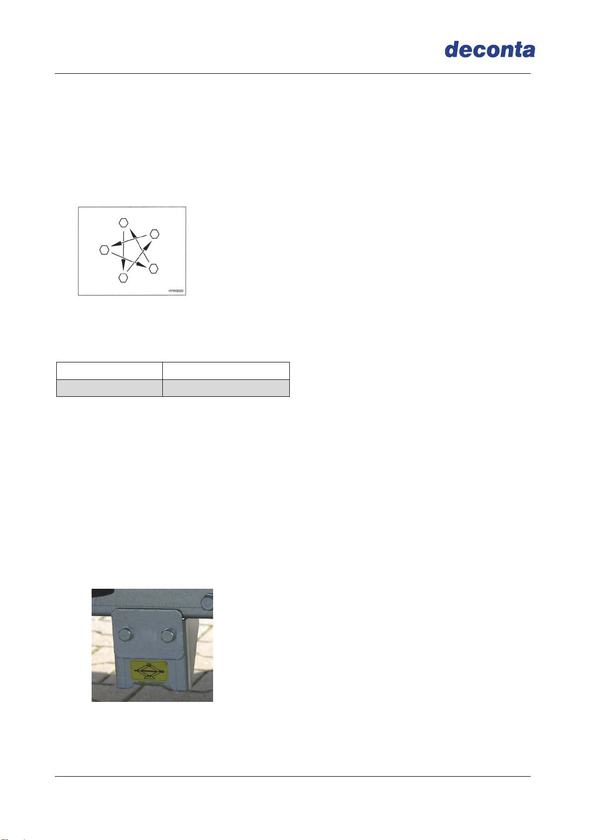
Tighten the wheel nut cross wise,
Tightening torsional moment 90 – 110 Nm.
Check again after first journey (after approx. 100 km).
Check the pressure of the cold trailer tyres regularly before the journey.
Tyres Pressure in bar
195 / 50 B 10 6,0
The statement of the value of the tyre pressure applies to the cold tyres. The trailer is steadily adapted to the newest
technical standard. It is possible that new tyres sizes are not considered in this chart. In this case, deconta provides
you the newest values.
Wheel change:
The trailer must stay on an even, firm and slip-free soil.
For the wheel change, please use the supplied car jack.
Before lifting the trailer, the hand brake has to be applied tightly.
Ensure that the trailer cannot roll away using wheel chocks placed on the opposite
side.
Do not ever lift the vehicle with the attached landing gear
Fix the car jack only in the provided and marked place.
Do not lay down under the lifted trailer
If you use wheel rims or tyres which are not allowed for the trailer, the road traffic
security can be affected.
Guide book
D 3000 / 4000 / 5000
Seite 7
1. 5 Transport/ towing, coupling and axle load
The important for the choice of the towing vehicle
and trailer are statements which are listed in the
registration certificate and defined in the operation
limits.
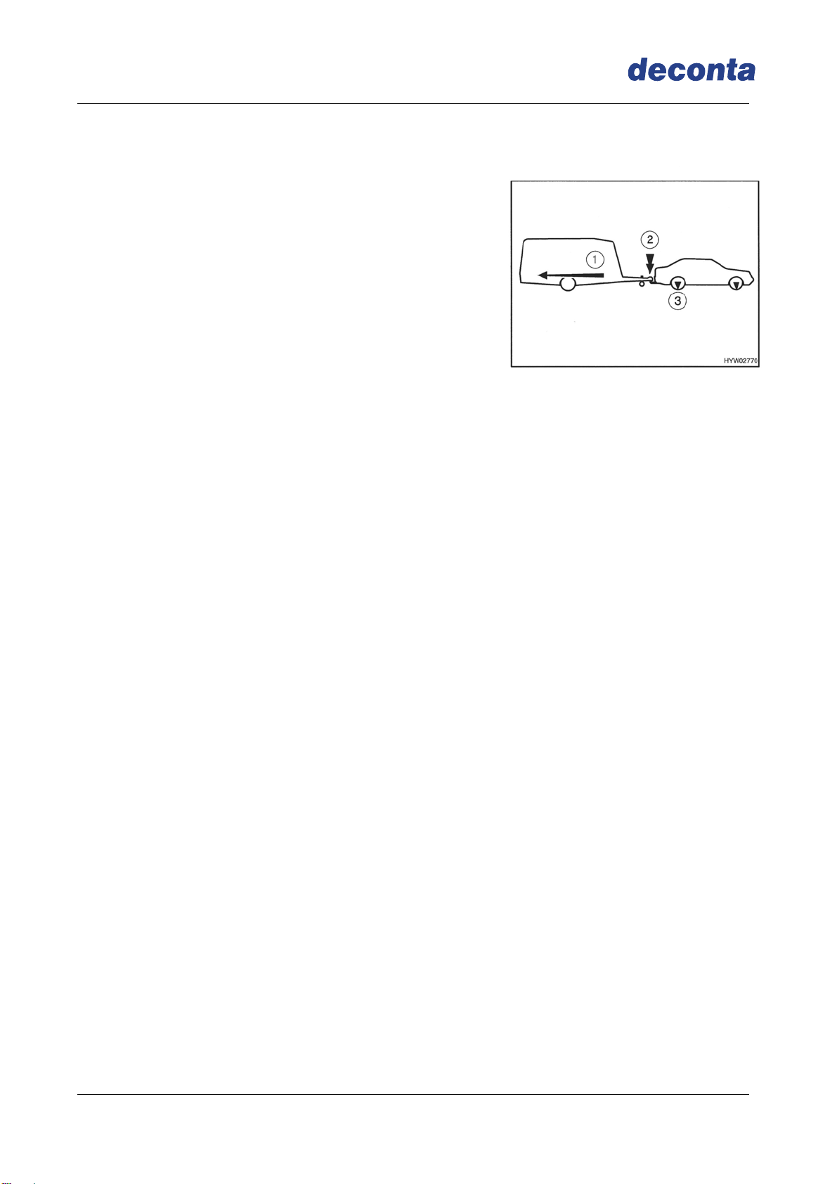
The quoted trailer load of the towing vehicle gives
information about which maximal weight the towing
vehicle is allowed to tow.
The coupling load indicates with which power the
drawbar of the trailer is allowed to press on the on
the tow-bar of the towing vehicle. The maximal
permitted coupling load may not be exceeded and
the minimal coupling load may not be undercut
The Transport of the trailer is only permitted with
vehicles which can prove the coupling load listed in
the operation limits for their tow-bar.
The axle load accounts for the permitted peak load
for the front and back axle of the towing vehicle and
may not be exceeded by the trailer.
1.6 Coupling
Manoeuvre towing vehicle and trailer to the coupling point
Do not couple the trailer with overrunning brake
Manoeuvre the trailer with help of the drawbar jockey wheel onto the towball of the
towing vehicle
Put the open coupling (coupling head handle pulled upwards) and wind down the
jockey wheel on the tow-bar of the towing vehicle
The coupling head handle locks independently and audibly (if necessary press
downward additionally with the hand); locking and securing happen automatically
Wrap the breakaway cable with a loop around the towball of the tow-bar of the towing
vehicle.
Wind the jockey wheel up fully and clamp securely in the direction of travel
Connect trailer electric plug of the trailer in the socket of the towing vehicle and take
care that the connection cables do not drag on the road
Check the lights
Remove all wheel chocks
Slacken the handbrake
1 Trailer load
2 Coupling load
3 Axle load

Guide book
D 3000 / 4000 / 5000
Seite 8
Caution:
It is only coupled correctly when the green cylinder of the locking display becomes
visible. Please mind that the inside of the coupling is not dirty and that the
movable parts are smooth-running.
1.7 Uncoupling
Apply hand-brake of the trailer fully
Secure trailer by chocking both wheels an
Remove the breakaway cable of the towing vehicle
Unplug the light plug and fix it in the holder on the drawbar
Wind down the jockey wheel until it has firmly reached the soil
Push firmly the coupling handle upwards and slacken
Raise the drawbar with help of the jockey wheel as far as one can drive away without
danger
After the uncoupling respect following:
Place the trailer on a straight and even surface
Secure the trailer against rolling backwards even by slopes or descents
1. by applying the fixing brake of the drawbar
2. by placing the chocks under the wheels
Lower the landing gear in order to give the trailer a safe position.
1.8 Reverse track
With a reverse automatic the backing up of the trailer is possible without problems. In
addition to a rolling resistance, a remaining brake force has to be overcome.
Locking display

Guide book
D 3000 / 4000 / 5000
Seite 9
2 Technical description
The mobile lock is a multi-chambers system which enables the gradual entry in a
contaminated area as well as the leaving in various phases, without the spreading of
fibres.
In this mobile lock system, a negative pressure is produced in order to prevent the entry
in other rooms or outdoors of the asbestos fibres, whether through an air exchange or
spreading through e.g. the working suits.
Lock in and out process according to the country-specific laws.
Floor-, extern and intern walls in Sandwich construction.
Electric- Water heating
by 3 kW heating rod, 220 Liter stainless steel - fresh water tank, 230 Volt power
supply necessary for operation
Diesel- Water heating and room heating
Warm water heating through 4 kW WEBASTO - Diesel warm water producer,
220 Liter stainless steel - fresh water tank. An integrated battery enables the use
of all consumers without external current connection. (Autarkic operation, with a
connection of 230 Volt the batteries are loaded automatically)
Gas- Water heating
continuous flow heater with 11 kW, power supply of 230 Volt only necessary for
use of extra consumers, water connection necessary
Gas- Water heating autarkic
continuous flow heater with 11 kW, 4 x 30 Liter fresh water canister. An integrated
battery enables the use of all consumers without external current connection.
(Autarkic operation, with a connection of 230 Volt the batteries are loaded
automatically
Guide book
D 3000 / 4000 / 5000
Seite 10
3 Initial operation
3.1 Electric-Version
3.1.1 Energy supply
The electric supply takes place from the outside at the connection "Supply" (230 Volt). If
the supply has occurred, the socket inside the vehicle is activated.
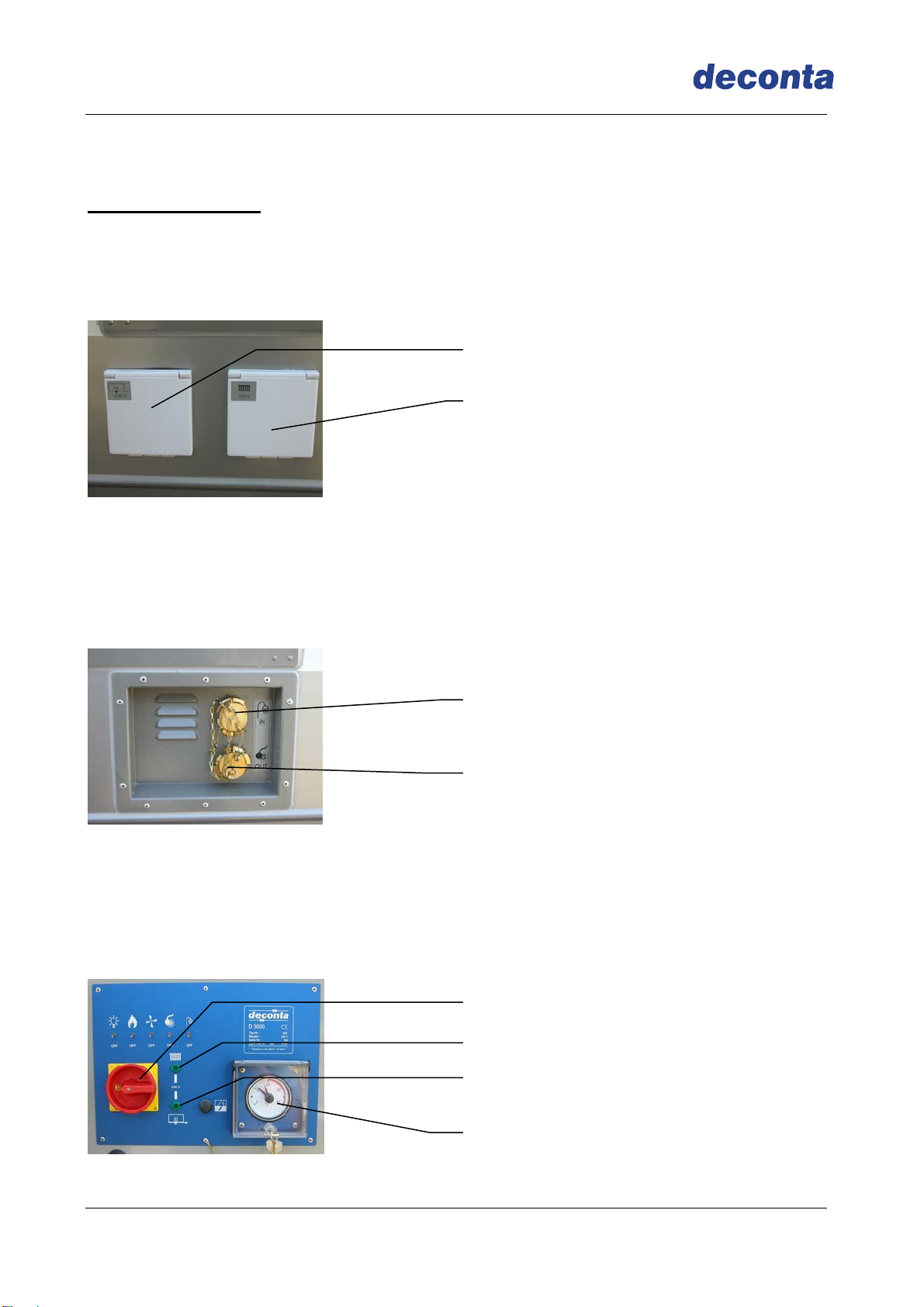
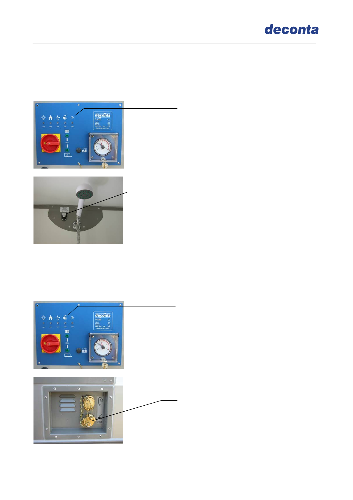
3.1.2 Tank filling
In the vehicle, there is 220 litres fresh water tank.
The filling occurs from the outside via the GEKA connection at the connection fresh
water.
Connect the fresh water hose and open the conduct
Switch on the main plug (if power supply is connected correctly the control lamps
basic function and heating are illuminated)
Tank fills up to minimal mark
To reach desired shower temperature move red hand in thermostat
(usually onto 36-37°C)
Connector fresh water
Connector sewage water
Main plug
Thermostat
Power supply – basic function
Power supply – room heating
Control lamp heating
Control lamp basic function
Guide book
D 3000 / 4000 / 5000
Seite 11
Switch on the water heating. The water in the tank is heated up to the chosen
temperature.
When the water in the tank has reached the required temperature, fresh water is
automatically added.
If the temperature in the tank drops about 2°C, the fresh water supply will be
stopped and the water will be heated again.
This procedure is repeated until the tank has been fully filled.
Thanks to this way of filling (Step by Step) you have after a short time tempered shower
water at your disposal.
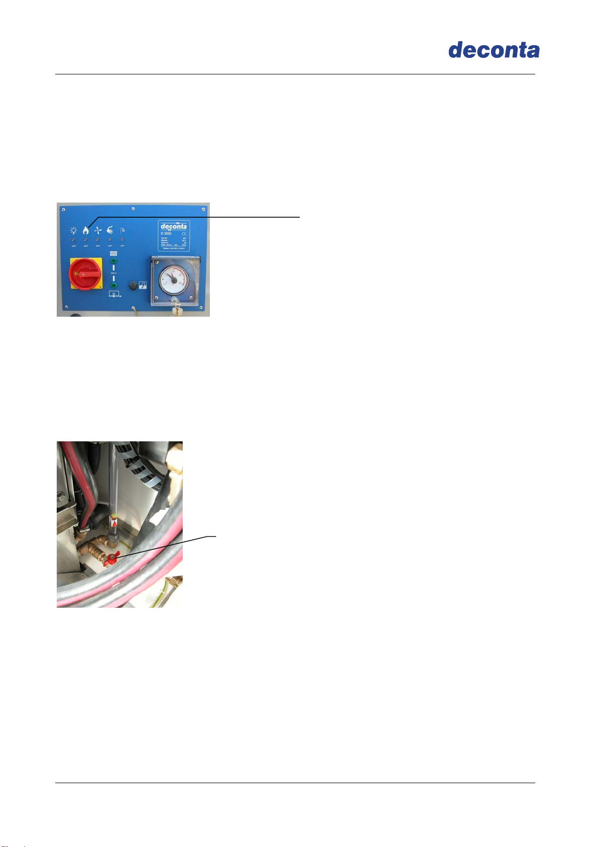
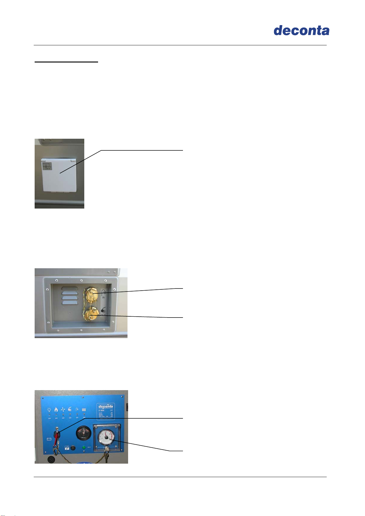
ATTENTION: Never drive the trailer with a full tank!
For the emptying of the tank, there is a ball valve placed in the technical room. If you
open it, all the water runs out under the vehicle
3.1.3 Room heating (optional equipment)
Room heating through 2000 Watt Wall heater. A thermostat at the wall heater regulates
the desired room temperature.
Water heating
Ball valve for draining of
tank

Guide book
D 3000 / 4000 / 5000
Seite 12
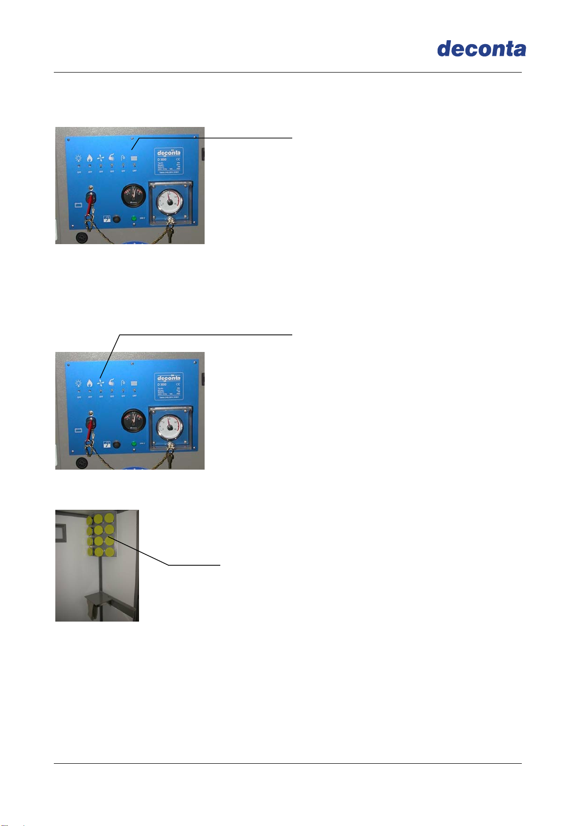
3.1.4 Negative pressure plant (optional equipment)
To avoid the danger of the spreading of dust out of the dirty area to the clean area, all
rooms are ventilated. In the dirty area, the air is sucked in and blown out through P3
filters.
Through the fresh air openings, the shower and the clean area are also ventilated. The
fresh air openings have been scaled in such a way that a pressure drop prevails going
from the dirty area to the clean area.
Negative pressure plant
Negative pressure plant
Guide book
D 3000 / 4000 / 5000
Seite 13
3.1.5 Shower
The switch shower in the technical room switches the shower water pump ready for use.
The shower procedure can only be started and stopped via the switch „Shower procedure
Start“.
3.1.6 Sewage water filtering plant (optional equipment)
If the switch „Sewage water filtering plant“ is switched on in the technical room, the
sewage pump starts automatically if you switch the switch „shower water start“ and
pumps the dirty shower water via 2 steps filtering plant. The filtered sewage water comes
out at the connection „filtered sewage water“.
Shower procedure Start
Shower
Sewage water filtering plant
filtered sewage water

Guide book
D 3000 / 4000 / 5000
Seite 14
Filter sizes:
Prefilter 10“ :220
Finefilter 10“ : 1(other sizes on demand)
max. medium temperature : 50°C at 4bar
Please note:
If the switch sewage water filtering plant is not activated, no sewage water filtering
takes place during the shower procedure. The consumed shower water comes out
from the connection „non filtered sewage water.
Prefilter
Finefilter
unfiltered sewage water

Guide book
D 3000 / 4000 / 5000
Seite 15
3.1.7 Filter change
filter change only when device is deactivated
dismount the dirty filters in a wet state in order to avoid the release of filter dust
only use authorized filters
damaged filter candle may not be used
The sewage water filters have to be changed if the power of the sewage water
pump decreases. We recommend by normal consumption of dirty water a weekly
change, by stronger strain a daily change.
Slacken cap nut
Take out the filter and dispose of it
Keep filter glas and sealing face clean
Insert new filter candles
Screw on cap nut with key carefully
Suction hoses, pumps, filter housings and filter are already contaminated by the
first use. Repairs and maintenance works are only allowed to be undertaken in
observing the security measures.
All mentioned filters must be disposed of according to the regulations required by
law.
3.1.8 Light
Through the activation of the switch light, the LED-lighting in the vehicle is switched on.
Light
Key

Guide book
D 3000 / 4000 / 5000
Seite 16
3.2 Electric-Version with forced locking
The general start-up is done as described in item 3.1.
3.2.1 Activation of the forced locking
The control of the forced locking is to be found in the clean area.
Make sure both doors to the shower room are closed.
Position key switch on „Test“, the green keys of the door case illuminate. After 5 Sec. s,
switch to „Automatic“, the forced locking is now activated and the green keys are still
glow.
3.2.2 Lock system procedure
Step into shower cabin from clean area. The forced locking is not yet activated.
Press green key on door case to shower cabin, door can be opened.
Step into shower cabin
Close the door
Press green key on door case to the dirty area, door can be opened.
Close the door.
Key switch

Guide book
D 3000 / 4000 / 5000
Seite 17
When entering the shower cabin from the dirty area the forced locking is activated.
Press green key on door case to shower cabin, door can be opened.
Enter shower cabin
Close the door
Shower is activated for a default time of 90 sec.
After finishing the showering procedure press green key on door case to clean
area, door can be opened.
Leave the shower cabin and close the door.
All door cases have an emergency off-key (red key) to enable an early exit out of the
shower cabin with forced locking.
By pressing the red key all doors open and an acoustic signal is heard.
Guide book
D 3000 / 4000 / 5000
Seite 18
3.3 Diesel-Version
3.3.1 Energy supply
The electric supply takes place from the outside at the connection "Supply" (230 Volt). If
the supply has occurred, the sockets inside the vehicle are activated.
The autarkic version enables an integrated on-board battery to make use of all
consumers without external power supply. When connecting to 230V the battery is
automatically reloaded.
IMPORTANT! The battery loads only when main switch is turned on!
3.3.2 Tank filling
In the vehicle, there is 220 litres fresh water tank.
The filling occurs from the outside via the GEKA connection at the connection fresh
water.
Connect the fresh water hose and open the conduct
Switch on the main plug (if power supply is connected correctly the control lamps
basic function and heating are illuminated)
Tank fills up to minimal mark
To reach desired shower temperature move red hand in thermostat
(usually onto 36-37°C)
Connector fresh water
Connector sewage water
Battery-Main switch
Thermostat
Power supply basic function

Guide book
D 3000 / 4000 / 5000
Seite 19
Switch on the water heating. Make sure the Diesel jerry can is sufficiently filled.
The Diesel-Water heater starts. Due to the length of the hose from canister to
the warm water heater, it might happen that not enough diesel reaches the
burner. The warm water heater switches off (pay attention to running
noises). In this case switch off the water heating and switch on again after
about 1 min. Repeat this procedure 2 -3 times, if necessary.
The water in the tank is heated up to the chosen temperature. When the water in
the tank has reached the required temperature, fresh water is automatically
added.
If the temperature in the tank drops about 2°C, the fresh water supply will be
stopped and the water will be heated again.
This procedure is repeated until the tank has been fully filled.
Thanks to this way of filling (Step by Step) you have after a short time tempered shower
water at your disposal.
ATTENTION: Never drive the trailer with a full tank!
For the emptying of the tank, there is a ball valve placed in the technical room. If you
open it, all the water runs out under the vehicle.
Water heating
Ball valve for draining of
tank
Guide book
D 3000 / 4000 / 5000
Seite 20
3.3.3 Room heating
The space heater can be switched on/off in the plant room.
3.3.4 Negative pressure plant (optional equipment)
To avoid the danger of the spreading of dust out of the dirty area to the clean area, all
rooms are ventilated. In the dirty area, the air is sucked in and blown out through P3
filters.
Through the fresh air openings, the shower and the clean area are also ventilated. The
fresh air openings have been scaled in such a way that a pressure drop prevails going
from the dirty area to the clean area.
Negative pressure plant
Negative pressure plant
Space heater
This manual suits for next models
2
Table of contents
Other deconta Safety Equipment manuals

Popular Safety Equipment manuals by other brands

safemax
safemax LEVEL 2 PROTEKTOR 2.0 User information

Milwaukee
Milwaukee BOLT User instructions

babcockdavis
babcockdavis Lume-A-Lite BEM-DSH1-10 Installation, operation and maintenance manual

ABS Safety
ABS Safety UniGlide PRO manual

BosStrap
BosStrap Side Slide instructions

MEDIKOKIM
MEDIKOKIM SAFEBELT user manual


Tractel
Tractel FABA-Klassik A11 Operating and maintenance instructions

Innotech
Innotech UNI-EAP-01 manual

ANT+
ANT+ CSN515 Operation manual

Tractel
Tractel skysafe MP 03 Assembly and operating manual

hepco & becker
hepco & becker 501948 00 01 instructions

Powerfix Profi
Powerfix Profi 77309 Instructions for use