1
Introduction
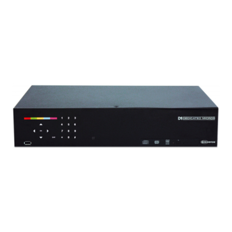
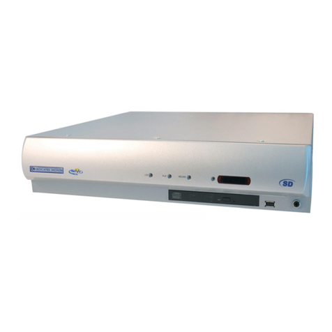
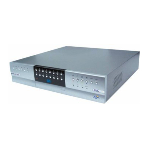
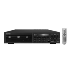
This addendum sheet applies to DS2 units with a built-in CDR. The DS2 CD has the following
features over the standard DS2:
1. Built-in CD Writer.
2. Onboard mains power supply.
Quick Install (Page 5)
The rear panel has now changed to:
VID 16VID 15VID 14VID 12VID 11 VID13
SERIAL2
VID 10
SERIAL 1
A
R1 R2
OUT
IN
AU XR ELAYS AUX ALARMS
VID 9VID 8VID 7VID 5VID 4 VID 6VID 3VID 2MO NMO N A V ID 1
MICLINESCSI
B
NE T
-+-
+
485 B U S
LINE
BUS A BUS B
DIRECT
GND
POWER
Connections at the rear of the DIGITAL SPRITE 2 CD
Video
VID1 to VID16 - 75ΩBNC composite camera connections (1V pk-pk).
MON A - Main monitor, 75ΩBNC composite monitor connection (1V pk-pk).
MON B - Spot monitor, 75ΩBNC composite monitor connection (1V pk-pk).
SVHS - Main monitor, S-video monitor connection.
Audio
MIC - 3.5mm mono jack connection, -50dBV sensitivity or better
(unbalanced Electret).
LINE IN - RCA (phono) socket, 47KΩ1V pk-pk.
LINE OUT - RCA (phono) socket, 1V pk-pk
Data
SCSI - 50-pin HD SCSI-2 connection.
NET - RJ-45 10-baseT Ethernet connection.
BUS A - RS-485 telemetry port 1.
BUS B - RS-485 telemetry port 2 (Used in conjunction with BUS A with Sensormatic
telemetry).
485 BUS - 2x MMJ ports for DM 485-BUS accessories.
SERIAL 1 - 9-way (Male) D-type RS-232 serial port.
SERIAL 2 - 9-way (Male) D-type RS-232 serial port.
Alarms and relays
R1 - Relay dry contact, NO/NC.
R2 - Relay dry contact, NO/NC.
DIRECT - Direct auxiliary input, NO.
ALARMS IN - 25-way (Female) D-type programmable direct alarms, NO/NC.
RELAYS - 9-way (Female) D-type individual activity detection relays, NO.
Built-in CD writer
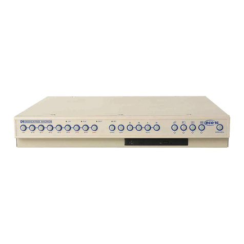
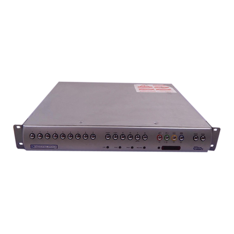
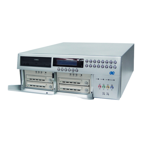
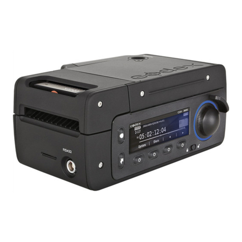
The Digital Sprite 2 CD has a built-in CDR accessible from the front panel.
The operation of the internal CDR is identical to using the external CDR as described on the
Quick Setup Card.
Note: Although the CDR has a DVD-ROM label on the drawer it is not possible to read or write to
DVD media.
To insert a CDR:
1. Press the button on the CDR drawer
2. Pull the CD drawer out until there is resistance
3. Place the CDR with the writing side up on the spindle and press down until there is a
click.
4. Push the drawer back in until it latches.
To remove a CDR:
1. Press the button on the CDR drawer
2. Pull the CD drawer out until there is resistance
3. Hold the CDR between thumb and forefinger and lift to remove from the spindle.
4. Push the drawer back in until it latches.
Note: In the event of a CD becoming jammed in the drive, or a power failure, it is possible to
open the CDR drawer by inserting a thin object such as a paper clip, or watchmaker’s
screwdriver into the small hole in the CDR drawer and applying pressure until the drawer
unlocks.
WARNING: The CDR is a Class 1 laser product to EN 60825-1:1994, avoid exposure to the beam.
Selecting CD-Rs and CD-RWs
The internal CD writer in the Digital Sprite 2 is not compatible with Ultra Speed CDR’s. Ensure
that only High Speed or Multi-Speed CDR media is used. This is normally written on the CDR
packaging and on the disk itself.
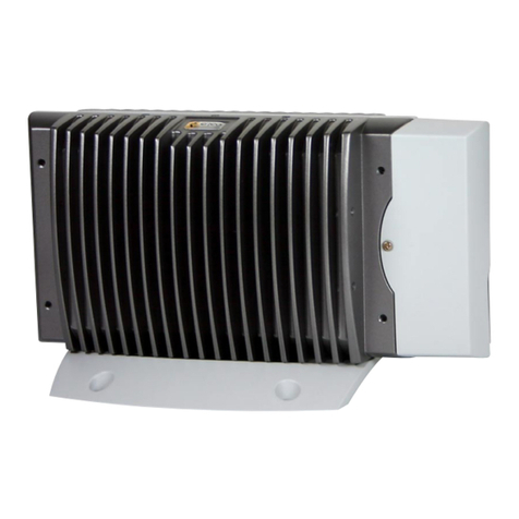
On-board power supply
Previous models of Digital Sprite and Digital Sprite 2 units used an external PSU. The Digital
Sprite 2 CD has an on-board mains power supply.
To apply power to the Digital Sprite 2 CD :
1. Ensure all cameras, monitors and other connections are made, before continuing.
2. Insert the supplied IEC power lead into the Power socket at the rear of the unit.
3. Plug the unit into the power socket on the wall and switch on.


