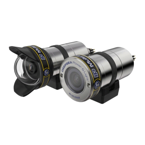
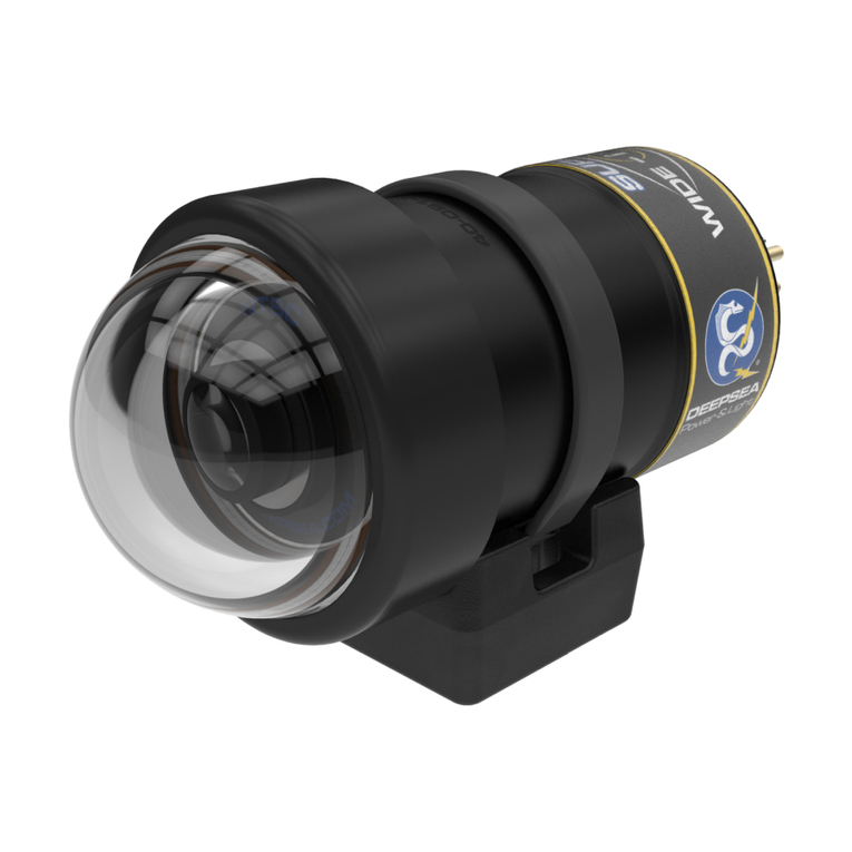
DeepSea Power & Light IP Multi SeaCam IPMSC-3070 User manual

Operator’s Manual
WARNING!
Read this Operator’s Man-
ual carefully before using
this tool. Failure to under-
stand and follow the con-
tents of this manual may
result in electrical shock,
fire, and/or serious per-
sonal injury.
Original Instructions – English – 1
IP Multi SeaCam
®

2
IP Multi SeaCam®
Table of Contents
Table of Contents ........................................................................................................................... 2
Specication Overview .................................................................................................................. 3
Safety Symbols............................................................................................................................... 4
General Safety Information............................................................................................................ 4
Equipment Use and Care............................................................................................................ 4
Integration Procedure .................................................................................................................... 5
Integrating Instruction.................................................................................................................. 5
Video Output ............................................................................................................................... 5
System Setup.................................................................................................................................. 5
Controls and Operation ................................................................................................................. 5
Power Over Ethernet and DC Power .......................................................................................... 5
SD Card Formatting .................................................................................................................... 5
Camera Controls and Indicators ................................................................................................. 5
Record, Playback, and Download............................................................................................... 5
SeaSense Protocol Information .................................................................................................. 5
Web Based User Interface.......................................................................................................... 6
Maintenance and Repair ................................................................................................................ 6
Flooding Repair Procedure ......................................................................................................... 6
Troubleshooting .......................................................................................................................... 7
RMA Procedure for Repair.......................................................................................................... 7
Warranty Information ..................................................................................................................... 7
Limited Warranty ......................................................................................................................... 7
Appendix A SeaSense Serial Interface Modication....................................................................... 8

3
Specication Overview
* Specications subject to change without notice.
Operator’s Manual
IPMSC-3070
Flat Port
IPMSC-3105
Dome Port
Optical Specications
Lens 2.7 mm, f/2.9
Focus Fixed, 100 mm~innity
FOV in Water 72° H x 42° V 105° H x 60° V
Video Specications
Image Sensor 1/2.8” CMOS
Sensor Resolution 1920 x 1080
Measured Resolution TBD
Faceplate Illumination 0.095 Lux [50 IRE]
Signal to Noise TBD
Interface Specications
Supported Protocols TCP/IP, UDP/IP, RTP, RTSP, SNTP, HTTP, FTP, DHCP, DNS, UPnP,
ONVIF
Interface Browser
Video Compression h.264, MJPEG
Bit Rate Control VBR, CBR1
Bit Rate h.264: 1~20 Mbps, 10 Mbps1
MJPEG: 1~50 Mbps, 50 Mbps1
Latency2h.264: 237 ms
MJPEG: N/A
Benchmark Latency3h.264: 488 ms
MJPEG: 432 ms
Max Frame Rate 30 FPS
Integrated Recording HD MPEG Video, HD JPEG Stills
Onboard Memory 256 GB (SDHC)
Conguration Settings Browser (Chrome, Firefox, IE), ONVIF Prole S
Environmental Specications
Depth Rating 4,000 m 6,000 m
Optional 11,000 m4
Operating Temp TBD
Storage Temp -30° C to 70° C [-22° F to 158° F]
Electrical Specications
Voltage 10~36 VDC, Power Over Ethernet (IEEE802.3af)
Power 2W max
Mechanical Specications
Housing Titanium
Port Sapphire Borosilicate Glass
Outer Diameter 56.4 mm [2.22 in.] 69.1 mm [2.72 in.]
Overall Length 102.8 mm [4.05 in.] 124 mm [4.88 in.]
Weight in Air TBD TBD
Weight in Water TBD TBD
Connector
Default SEACON MCBH8-NET
Please contact sales for more options.
1.87
47.4
1.59
40.3
2.04
51.7
2.72
69.1
4.88
124.0
6.29
159.8
2.90
73.6
mm
[inch]
DOME PORT
4.05
102.8
5.46
138.6
2.22
56.4
1.87
47.4
1.20
30.5
1.59
40.3
2.65
67.3
mm
[inch]
FLAT PORT
1.87
47.4
1.59
40.3
2.04
51.7
2.72
69.1
4.88
124.0
6.29
159.8
2.90
73.6
mm
[inch]
DOME PORT
4.05
102.8
5.46
138.6
2.22
56.4
1.87
47.4
1.20
30.5
1.59
40.3
2.65
67.3
mm
[inch]
FLAT PORT
1.87
47.4
1.59
40.3
2.04
51.7
2.72
69.1
4.88
124.0
6.29
159.8
2.90
73.6
mm
[inch]
DOME PORT
1.87
47.4
1.59
40.3
2.04
51.7
2.72
69.1
4.88
124.0
6.29
159.8
2.90
73.6
mm
[inch]
DOME PORT
1Factory default selection.
2Minimum latency measured using PC based
software decoder, optimized network port priority.
3Benchmark latency streamed with VLC, 50 ms
buer.
4Please contact sales for 11,000 m depth rating
connector options.

4
IP Multi SeaCam®
Safety Symbols
In this operator’s manual and on the product, safety symbols and signal words communicate
important safety information. This section is provided to improve understanding of these signal
words and symbols.
This is the safety alert symbol. It is used to alert you to potential personal injury hazards. Obey all safety messages that follow this symbol
to avoid possible injury or death.
DANGER indicates a hazardous situation which, if not avoided, could result in death or serious injury.
WARNING indicates a hazardous situation which, if not avoided, could result in damage to the product or bodily harm.
CAUTION indicates a hazardous situation which, if not avoided, could result in minor or moderate injury.
NOTICE indicates information that relates to the protection of property.
This symbol means read the operator’s manual carefully before using the equipment. The operator’s manual contains important
information on the safe and proper operation of the equipment.
This symbol means always wear safety glasses with side shields or goggles when handling or using this equipment to reduce the risk of
eye injury.
This symbol indicates the risk of electrical shock.
This symbol indicates the risk of electrostatic discharge (ESD). Always use ESD safe practices when handling equipment.
This symbol indicates a potentially hot surface that may cause burns or ignition.
CAUTION
NOTICE
DANGER
WARNING
General Safety Information
Do not operate any high voltage electrical equip-
ment in or around water without using a Ground
Fault Circuit Interrupter (GFCI) and an isolation
transformer, especially when divers are in the water.
Never place the camera in a vice or other hard
clamping tool. Should it become necessary to hold
the camera tighter than can be managed by hand,
use a clean, good quality strap wrench.
Equipment Use and Care
●The IP Multi SeaCam supports a variety of con-
nectors. Verify pinout orientation before use.
●Before deployment, check that the rear bulkhead
connector assembly is secure. Check that the
connectors are fully seated and that the seals are
engaged. Failure of the strain relief provisions
may damage the connectors and other elements
of the system.
●Before and after each deployment, check the fol-
lowing areas for damage, wear or corrosion:
a. Rear bulkhead connector assembly
b. Video cable
c. Front Window
d. Retaining cowl
●Rinse the Apex SeaCam in fresh water after use
in saltwater.
After each deployment, carefully check to make sure
the camera has not flooded. It is possible for the
camera to partially flood and then reseal itself while
underwater.
DANGER
WARNING WARNING

5
Operator’s Manual
Upon surfacing, the camera can become internally
pressurized. If the power remains on when the cam-
era has partially flooded, it is possible for electro-
lytic generation of an explosive mixture of hydrogen
and oxygen gases.
If a camera appears flooded upon removal from the
water, it should be treated as potentially dangerous.
Remove potentially flooded equipment and service
immediately. Point the camera away from persons
and valuable equipment and make sure that the
power is disconnected. See the “Flooding Repair
Procedure” on page 6 for more information.
Integration Procedure
Integrating Instruction
1. Make sure the power supply is in the OFF position.
Prepare a power supply with 10~36 VDC output.
2. Connect the camera power, SDI video, and con-
trol signals to their respective interfaces per the
pinout specied for the camera.
3. Prepare the camera bulkhead connector and verify
proper lubrication of all O-rings and seal surfaces
with a silicone lubricant (spray recommended).
4. Mate the female underwater connector to the
male bulkhead using a smooth linear motion.
Check that the connectors are fully seated and
that the seals are engaged.
5. Hand tighten the locking sleeves together until
rm. Do not over-tighten or use tools on the lock-
ing sleeves.
6. The camera is now ready for operation. Switch
the power supply ON to power the camera. The
camera draws a max of 12W during operation and
will work when supplied with 10~36 VDC.
System Setup
The following component requirements are examples
for integrating the IP Multi SeaCam on a system. Actual
setup will vary with each system depending on equip-
ment, camera conguration, and other factors.
Controls and Operation
Power Over Ethernet and DC Power
Information about this.
SD Card Formatting
The IP Multi SeaCam comes with a standard 256 GB
micro SDXC ash memory card for onboard video and
still image storage.
DeepSea recommends formatting the onboard memory
card outside of the camera. The camera has limited
formatting capability and may not properly format the
onboard memory from the web user interface.
The microSDXC memory card is formatted to vFAT
(32-bit). Replacement memory cards should also be
formatted to vFAT (32-bit). See (TBD SECTION) for
information on formatting additional microSDXC memory
cards.
Camera Controls and Indicators
Outlines common capabilities, as well as unit controls.
Record, Playback, and Download
Outlines how to record, playback, download, etc. if not
covered in above section.
SeaSense Protocol Information
The DeepSea Power & Light SeaSense serial protocol
controls enabled products in real time over standard
EIA-485 (RS-485) and EIA-232 (RS-232) industrial serial
communications interfaces.
While the physical topology of these serial interfaces
may dier, this protocol is designed to operate in each
environment. The SeaSense protocol uses ASCII char-
acter commands for human readability. Strict command
string formatting and an optional check-sum eld oer
robust, error-tolerant communications in harsh environ-
ments and mixed-protocol network installations.
DeepSea Power & Light recommends host-side elec-
trical isolation to the physical serial interfaces when
used in subsea environments to limit risks to the host
platform.
The SeaSense protocol provides exibility in the use
and operation of the Apex SeaCam. With this protocol,
operators and system integrators can:
●Control video test patterns to troubleshoot video
transmission systems as well as identify video
feeds.
●Monitor system parameters and diagnostic infor-
mation such as total run time, internal tempera-
ture, and number of power cycles.

6
IP Multi SeaCam®
Maintenance and Repair
Flooding Repair Procedure
If the camera stops working while underwater, assume
that it has ooded. When working on a potentially
ooded camera, use appropriate personal protective
equipment to protect hands, body, and eyes.
1. Immediately turn o the power to the unit.
2. Open the housing by removing the rear-end
cap-retaining ring.
3. Separate the two components by gently pulling
them apart. If necessary, lightly twist components
while separating.
4. Pour out any water trapped in the housing.
5. If the camera is completely ooded, rinse the
internal components with clean fresh water to
minimize contamination and corrosion.
6. Allow parts to dry in air or in a convection oven set
to 60° C (140° F).
NOTICE DeepSea Power & Light cannot be
responsible for any damage incurred during emer-
gency eld repairs. Such repairs should be under-
taken only as a last resort and by qualied
personnel.
Troubleshooting
If the camera stops working while underwater, assume
that it has ooded. See “Flooding Repair Procedure” on
page 6 for more information.
Once determined that the camera is not ooded, or if it
does not turn on during pre-deployment checks, trouble-
shoot in the following sequence:
1. Check that the cable/inline connector has the
correct voltage and current supplied, and that the
correct sockets are being used. See “Electrical
Specications” on page 3 of this manual for elec-
trical specications.
2. Remove the connector and inspect the assembly
for visual signs of wear. Use a multi-meter check
for continuity or shorts. If available, try a spare
connector in the camera.
3. Check the wires that go from the power supply to
the camera base for wear. If they appear worn,
replace them.
4. Check that the power supply board is securely
attached to the camera. If it is loose, check for
damage on the board. If no damage is visible,
●Configure the serial interface by setting baud
rates, device addresses, switching between EIA-
232 or EIA-485 serial interfaces, and enabling a
termination resistor for EIA-485 operation.
●Control power usage with a low power standby
mode or a limit on the maximum light output level.
●Switch between sixteen user preset states for
standby mode and configure the power-on state to
one of these user presets.
●Operate multiple units over a single serial inter-
face and use group addresses (up to 32 per de-
vice) or send global address to efficiently control
more than one device with a single command.
The SeaSense Protocol Specication document is
available at www.deepsea.com/SeaSense_Protocol_
Specication.pdf
Web Based User Interface
A web user interface (UI) is available with the
IP Multi SeaCam IP address. The default UI is
httpL//192.168.1.250. Any changes to the camera IP
address will change the http:// UI address.
Camera settings can be adjusted in the Web UI Menu
Structure.
System Setup
User Set or reset user name and password
Date & Time
Update
Save/Load Settings
Image Setup
IRIS
Exposure
Backlight
Color
Picture
Motion
Output Set
System
Video Setup
Video
H.264 View
JPEG View
Network Setup
Ethernet
SD Card Setup
Info

7
Operator’s Manual
reattach the board to the camera or try a spare
driver board.
5. If the camera still does not work, return it
to DeepSea Power & Light using the “RMA
Procedure for Repair”.
RMA Procedure for Repair
For warranty and non-warranty repairs, contact Deep-
Sea Power & Light for an RMA number prior to returning
the item. Please include the model number, serial
number, and any other pertinent information along with a
description of the problem.
Tel: 858-576-1261
Fax: 858-576-0219
Email: [email protected]
When shipping the item, be sure that the freight is
prepaid (CODs will not be accepted) and that the RMA
number is clearly printed on the outside of the box.
Send all shipments to the following address:
DeepSea Power & Light
Attn: RMA ####
4033 Ruffin Road
San Diego, CA 92123-1817
U.S.A.
Warranty Information
Limited Warranty
Seller warrants that the goods (except internal electronic
components) sold under this contract will be free from
defect in material and workmanship for a period of one
year from the date of shipment from the factory, if they
have been properly used. Internal electronic compo-
nents are warranted for 90 days from the date of ship-
ment from the factory, if they have been properly used.
This warranty will be limited to the repair or replacement
of parts and the necessary labor and services required
to repair the goods. IT IS EXPRESSLY AGREED THAT
THIS WARRANTY WILL BE IN LIEU OF ALL WARRAN-
TIES OF FITNESS AND IN LIEU OF THE WARRANTY
OF MERCHANTABILITY. This warranty is the exclusive
and only warranty to pass with the goods under this
contract. No agent, employee, or representative of the
Seller has any authority to bind Seller to any information,
representation, or warranty concerning the goods sold
under this contract, and unless an armation, represen-
tation, or warranty made by an agent, employee, or rep-
resentative is specically included within this contract,
it will not be enforceable by Buyer. If notice of defect is
given to DeepSea Power & Light LLC within such 90
day or one-year warranty period, the sole obligation of
DeepSea Power & Light LLC shall be to furnish new or
repaired parts free of charge in exchange for parts which
have been proved defective and does not include any
other costs such as the cost of removal of the defective
part, installation, labor, or consequential damages of any
kind, the exclusive remedy being to require DeepSea
Power & Light LLC to furnish such new parts. Under no
circumstances shall the Buyer be entitled to recover any
incidental damages as that term is dened in Commer-
cial Code §2715.
T: (858) 576-1261
F: (858) 576-0219
www.deepsea.com

8
IP Multi SeaCam®
Appendix A
SeaSense Serial Interface Modication
Revision
Description
DCR
Approved by
Date
A
Initial Release
N/A
E. Bergstedt
1/4/2019
Name
Signature
Date
SeaSense Serial Interface
Modification
Originator
E. Bergstedt
1/4/2019
Operations
Engineering
Quality
Document Control
Document Number: 792-004-021
4033 Ruffin Road
San Diego, CA 92123-1813
4 January 2019
Sheet 1 of 3
REV A
All information contained in this document is confidential and proprietary to DeepSea Power and Light LLC. No license
expressed or implied, under any patent, copyright or trade secret right is granted or implied by the conveyance of this
document. No part of this document may be reproduced, transmitted, transcribed, stored in a retrieval system, translated
into any language or computer language, in any form by any means electronic, mechanical, magnetic, optical, chemical,
manual, or otherwise without the prior written permission of DeepSea Power and Light LLC.
http://nias/engineering/Shared Documents/Document Templates/DSPL_Manufacturing_Specification_Template.dotx

9
Operator’s Manual
SeaSense Serial Interface Modification
792-004-021
Version : 1.1
FOR RELEASE
2 of 3
4 January 2019
W:\792_DSPL_Docs\004_Oceano_Doc\792.004-021_SeaSense_Serial_Interface_Modification\792-004-
021_SeaSense_Serial_Interface_Modification.docx
DeepSea Power & Light
Serial Interface Modification
Notes
Device Interface Type is supported on the Apex SeaCam, HD ZOOM SeaCam, and LED SeaLite
products.
RealTerm is recommended when working through the RS232/RS485 interface.
TeraTerm is recommend when connected through a USB port.
Please reference DSPL_virtualComPort (http://www.deepsea.com/wp-
content/uploads/DSPL_virtualComPort.zip ) documentation for installing the device driver if
operating via a USB port.
Instruction
1) Changing the device over the RS232/RS485 interface requires Factory Unlocked mode. If you are
connected directly via the USB, skip to step 2. To enter Factory Unlocked mode:
a. Send !001:FACT? To the device
b. The !001:FACT? returns a randomized four character response combining letters and
numbers. Send this response back to the device to unlock the Factory Port (FPRT)
command. A successful command returns a <CR><LF> response.

10
IP Multi SeaCam®
SeaSense Serial Interface Modification
792-004-021
Version : 1.1
FOR RELEASE
3 of 3
4 January 2019
W:\792_DSPL_Docs\004_Oceano_Doc\792.004-021_SeaSense_Serial_Interface_Modification\792-004-
021_SeaSense_Serial_Interface_Modification.docx
2) Send !001:FPRT? The response will look similar to the image below.
The example response above indicates that the device is set to RS232 at 9600 baud rate.
3) Send !001:FPRT=RS4,1 to set the device to RS485 at the default 9600 baud rate.
To set RS485 at a different baud rate, enter:
!001:FPRT=RS4,2 for 19200 baud rate
!001:FPRT=RS4,3 for 57600 baud rate
To set the device to RS232, enter RS2 in place of RS4.
!001:FPRT=RS2,1 for 9600 baud rate
!001:FPRT=RS2,2 for 19200 baud rate
!001:FPRT=RS2,3 for 57600 baud rate
4) Send !001:SAVE to save the setting
5) Power cycle the device to implement changes

11
Operator’s Manual

© 2020 DeepSea Power & Light. All rights reserved. Rev 05/28/2020
Printed in USA
DeepSea Power & Light www.deepsea.com
4033 Run Road [email protected]
San Diego, CA 92123-181 T: 1-858-576-1261
USA F: 1-858-576-0219
This manual suits for next models
1
Table of contents
Other DeepSea Power & Light Digital Camera manuals

DeepSea Power & Light
DeepSea Power & Light DVS-300 User manual

DeepSea Power & Light
DeepSea Power & Light MSC 1050 User manual

DeepSea Power & Light
DeepSea Power & Light Super Wide-i SeaCam User manual

DeepSea Power & Light
DeepSea Power & Light SSC-5000 User manual

DeepSea Power & Light
DeepSea Power & Light Wide-i SeaCam WSC-3060 Black and White User manual

DeepSea Power & Light
DeepSea Power & Light SeaCam HDZSC-3045 User manual

DeepSea Power & Light
DeepSea Power & Light Wide-i SeaCam User manual

DeepSea Power & Light
DeepSea Power & Light Super Wide-i SeaCam User manual

DeepSea Power & Light
DeepSea Power & Light IP Multi SeaCam User manual