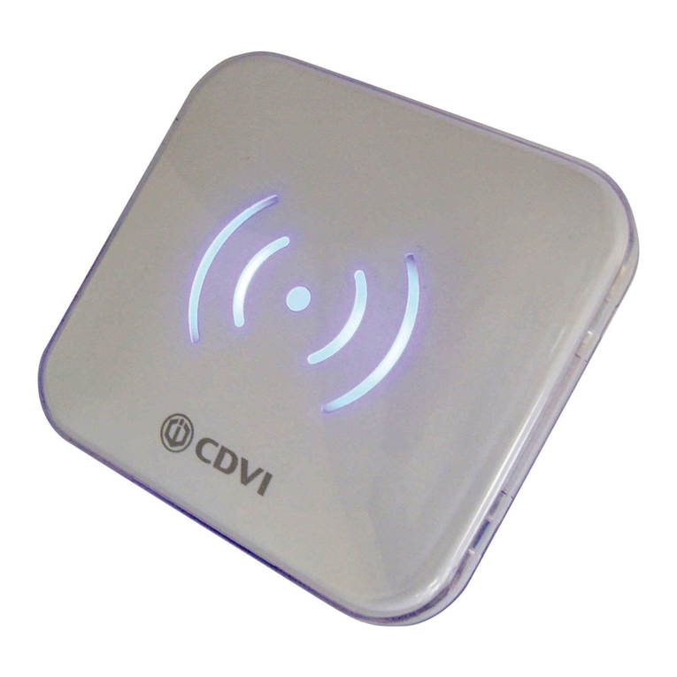
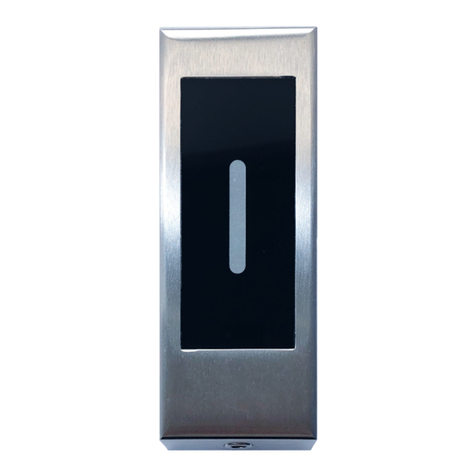
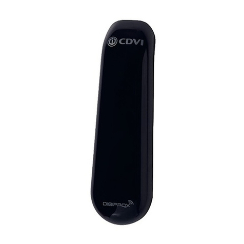
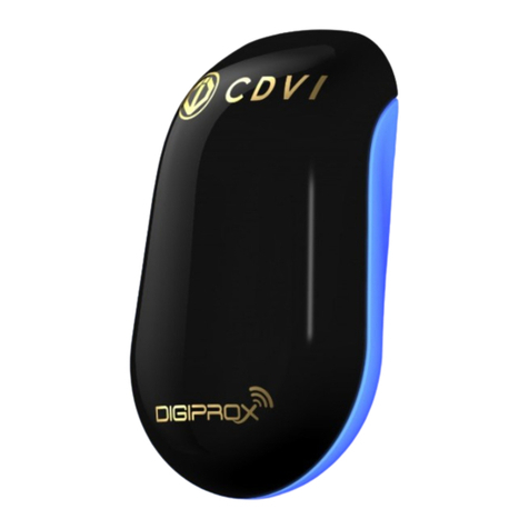
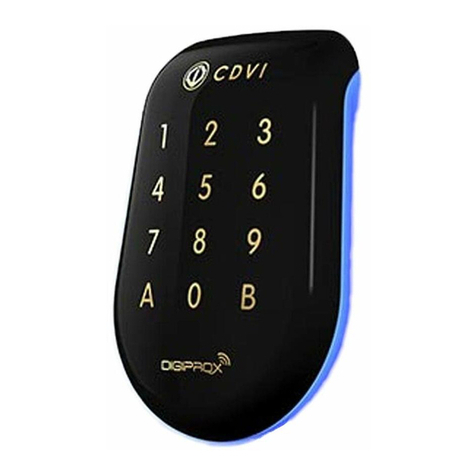
CDVI DGLPM WLC User manual

La elección del instalador
cdvigroup.com
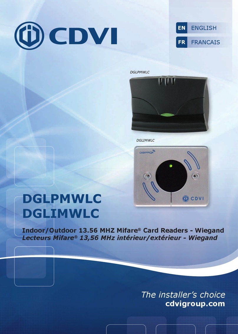
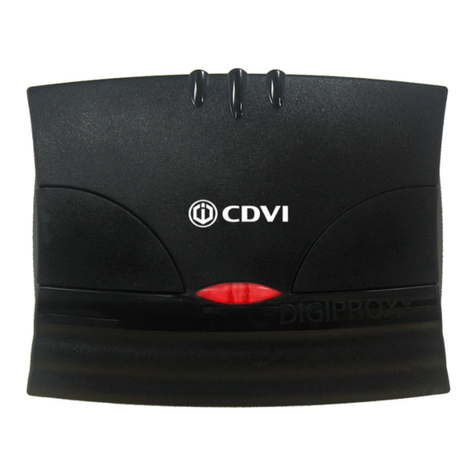
DGLPMWLC
DGLIMWLC
Lectores Mifare®13,56 MHz interior/exterior - Wiegand
Indoor/Outdoor 13.56 MHZ Mifare®Card Readers - Wiegand
ESPAÑOL
ES
ENGLISH
EN
DGLPMWLC
DGLIMWLC

77
98
19,50
DGLIMWLC
DGLPMWLC
1] PRESENTACIÓN DE PRODUCTOS
2] NOTAS Y RECOMENDACIONES
3] ELEMENTOS INCLUIDOS
Recomendaciones de instalación
Para asegura el sistema, no se olvide
de instalar un varistor en paralelo
a cada uno de los dispositivos de
cierre
.
Entorno
Si los lectores están en un
entorno cercano al mar o salino,
se recomienda barnizar los bornes
para prevenir la oxidación.
Fuentes de alimentación
ADC335, ARD12 y BS60.
Cable recomendado
Cable de 4 pares trenzados 6/10º
(AWG 24).
ANTIVANDÁLICO
IP53 -25°C a +70°C
Certicado CE
WEEE
Certicado FCC CFR 47
conforme parte 15
Gracias por conar en CDVI con la adquisición de este producto.
Wiegand 26, 30 o 44 bits.
Versiones disponibles:
- Acero inoxidable (DGLIMWLC).
- Policarbonato (DGLPMWLC).
Electrónica sellada con resina epoxi.
Señalización visual y sonora.
Montaje en supercie.
Tecnología: 13,56 Mhz.
Conexionado por cable de 4 pares 6/10º.
Alimentación: 12 Vcc.
Consumo: 100 mA.
Conforme a la directiva europea R&TTE 99/5/CE y sus normas
armonizadas ETS 301 489 y ETS
300-330-1-Ed 2001. Conforme a
las normas CEM aplicables:
EN 50133, EN 50130-4.
Varistor
Herramienta
Diax®
Torn. Diax®
5x35mm Anclaje
metálico Tapa
izquierda Tapa
derecha Taco de
jación
Tornillo
3x40mm
DGLIMWLC 1 1 2 2 - - - -
DGLPMWLC 1 - - - 2 2 2 2
2cdvigroup.com
ES
DGLPMWLC - DGLIMWLC
Lectores Mifare®13,56 MHz Wiegand
MANUAL DE INSTALACIÓN

5] ESQUEMA DE CONEXIONADO DGLPMWLC
ST5
ST6
ST5
ST6
1 1
ST1
ST2
ST1
ST2
ST1
ST2
26 BITS
30 BITS
44 BITS
ST4
ST4
1
1
ST4
1
ST5
ST6
ST5
ST6
1 1
ST1
ST2
ST1
ST2
ST1
ST2
26 BITS
30 BITS
44 BITS
ST4
ST4
1
1
ST4
1
ST5
ST6
ST5
ST6
1 1
ST1
ST2
ST1
ST2
ST1
ST2
26 BITS
30 BITS
44 BITS
ST4
ST4
1
1
ST4
1
ST5
ST6
ST5
ST6
1 1
ST1
ST2
ST1
ST2
ST1
ST2
26 BITS
30 BITS
44 BITS
ST4
ST4
1
1
ST4
1
ST5
ST6
ST5
ST6
1 1
ST1
ST2
ST1
ST2
ST1
ST2
26 BITS
30 BITS
44 BITS
ST4
ST4
1
1
ST4
1
ST4: Pulls up 12 V o 5V
Para salidas de colector abierto
existen dos posibilidades:
Este júmper permite escoger
el voltaje de salida en función
de la instalación.
DGLPMWLC*
- Bornero (8 puntos):
+Alimentación 12 Vcc
- 0 V
H Clock
D0 Data 0
D1 Data 1
B Buzzer
VLED verde
R LED rojo
ST1-ST2:
Formato de salida Wiegand
Formato de salida:
- Standard: 26 bits Wiegand.
- ST1: 30 bits Wiegand.
- ST2: 44 bits Wiegand.
ST5-ST6: LED
1
ST2
ST1
ST5
BH D0-
+
C3
-
+
-
+
ST6
ST4
1
Pulls up a 12 V
Pulls up a 5 V
Sin pull up
ST5
ST6
ST5
ST6
1 1
ST1
ST2
ST1
ST2
ST1
ST2
26 BITS
30 BITS
44 BITS
ST4
ST4
1
1
ST4
1
ST5
ST6
ST5
ST6
1 1
ST1
ST2
ST1
ST2
ST1
ST2
26 BITS
30 BITS
44 BITS
ST4
ST4
1
1
ST4
1
ST5
ST6
ST5
ST6
1 1
ST1
ST2
ST1
ST2
ST1
ST2
26 BITS
30 BITS
44 BITS
ST4
ST4
1
1
ST4
1
Comando por nivel
«O» (OV)
26 bits
30 bits
44 bits
Comando por nivel
«1» (+5V)
3cdvigroup.com
ES
DGLPMWLC - DGLIMWLC
Lectores Mifare®13,56 MHz Wiegand
MANUAL DE INSTALACIÓN

1
2
34
ON
ON
ONON
+ - H D0 D1 B V R
5] ESQUEMA DE CONEXIONADO DGLIMWLC
31 2 4
ON
OFF/OFF
26 bits
ON/OFF
30 bits
OFF/ON
44 bits
ON/ON
No usado
POSICIONAMIENTOS
DIPSWITCH 1 Y 2
ON
Modo Centaur
OFF
Modo CDVI
Puede controlar el buzzer
y los LED a través del
lector o un dispositivo
externo.
El controlador o sistema de
accesos gestionan los LED y el
buzzer para programar otras
opciones.
Al presentar una tarjeta se ac-
tiva el LED naranja y se emite
un pitido. El controlador CEN-
TAUR puede gestionar los LED
y el buzzer para programar
otras operaciones
POSICIONAMIENTO
DIPSWITCH 3
OFF
Pull up 5V
ON
Pull up 12V
Pulls up 12 V o 5V
Para salidas de colector abierto,
existen dos posibilidades
:
Seleccione la tensión de salida
en función de la instalación
.
POSICIONAMIENTO
DIPSWITCH 4
Bornero (8 puntos)
+Alimentación 12 Vcc
-0V
HClock
D0 Data 0
D1 Data 1
BBuzzer
VLED verde
RLED rojo
4cdvigroup.com
ES
DGLPMWLC - DGLIMWLC
Lectores Mifare®13,56 MHz Wiegand
MANUAL DE INSTALACIÓN

6] FORMATO DE SALIDA WIEGAND 26, 30 Y 44 BITS
Cronogramas
Salidas en colector abierto con pull ups internos de 1 K a +5 V o +12 V según posición de dipswitch ST4.
Formato Wiegand 26 bits
Formato de 26 bits hexadecimal.
La comunicación se efectúa por una conexión Wiegand de 26 bits (señales:
DATA1, DATA0 y CLOCK) en la que la trama se descompone de la siguiente manera:
1 - Primera paridad: 1 bit – paridad par de los primeros 12 bits.
Código del tag: 6 mitades de byte que representan los últimos 6 dígitos del código (4 bit = 1 dígito).
Cada byte se transmite desde el bit 7 al bit 0.
2 - Segunda paridad: 1 bit – paridad impar de los últimos 12 bits.
Bit 1 Bit 2 a bit 25 Bit 26
Paridad par de bit 2 a bit 13 Datos (24 bits) Paridad impar de bit 14 a bit 25
Ejemplo: para una tarjeta donde el código hexadecimal es 0100166A37.
1 0001 0110 0110 1010 0011 0111 0
Paridad 1 1 6 6 A 3 7 Paridad 2
El código que se transmite en hexadecimal es 166A37.
Paridad 1: “0” si el número de 1 desde el bit 2 al bit 13 es par.
“1” si el número de 1 desde el bit 2 al bit 13 es impar.
Paridad 2: “0” si el número de 1 desde el bit 14 al bit 25 es impar.
“1” si el número de 1 desde el bit 14 al bit 25 es par.
Lógica 0
\DATA1
\CLOCK
\DATA0
50 μs 50 μs
2ms 2ms
Lógica 1
5cdvigroup.com
ES
DGLPMWLC - DGLIMWLC
Lectores Mifare®13,56 MHz Wiegand
MANUAL DE INSTALACIÓN

Formato Wiegand 30 bits
Formato de 30 bits hexadecimal.
La comunicación se efectúa por una conexión Wiegand de 30 bits (señales:
DATA1, DATA0 y CLOCK) en la que la trama se descompone de la siguiente manera:
1 - Primera paridad: 1 bit – paridad par de los primeros 14 bits.
Código del tag: Se forma con 7 mitades de un byte.
Cada byte se transere desde el bit 7 al bit 0.
2 - Segunda paridad: 1 bit – paridad impar de los últimos 12 bits.
Bit 1 Bit 2 a bit 29 Bit 30
Paridad par de bit 2 a bit 15 Datos (28 bits) Paridad impar de bit 16 a bit 29
Ejemplo A: para una tarjeta cuyo código decimal es 689905 (en hexadécimal: A86F1).
1 0000 0000 1010 0110 0110 1111 0001 0
Paridad 1 0 0 A 8 6 F 1 Paridad 2
El código que se transmite en hexadecimal es 00A86F1.
Ejemplo B: para una tarjeta cuyo código en hexadecimal es 0100166A37.
1 0000 0000 0001 0001 0110 1011 0110 1
Paridad 1 0 0 6 6 A 3 7 Paridad 2
El código que se transmite en hexadecimal es 0166A37.
Paridad 1: «0» si el número de 1 desde el bit 2 al bit 15 es par.
«1» si el número de 1 desde el bit 2 al bit 15 es impar.
Paridad 2: «0» si el número de 1 desde el bit 16 al bit 29 es impar.
«1» si el número de 1 desde el bit 16 al bit 29 es par.
Formato Wiegand 44 bits
Formato de 44 bits hexadecimal. La comunicación se efectúa por una conexión Wiegand de 44 bits (señales:
DATA1, DATA0 y CLOCK) en la que la trama se descompone de la siguiente manera:
Datos: SN de 10 dígitos en hexadecimal (MSByte en primer lugar).
Cada dígito en hexadecimal = 4 bit (MSBit en primer lugar).
LRC: 4 bit = O restringido entre los dígitos de los datos (MSBit en primer lugar).
Bit 1 a bit 40 Bit 41 a bit 44
SN de la tarjeta, MSBit primero LRC
Ejemplo A: para una tarjeta EM cuyo código en hexadecimal es 01001950C3.
0000 0000 0000 0000 0001 1001 0101 0000 1100 0011 0011
01001950C33
El código que se transmite en hexadecimal es 01001950C3.
6cdvigroup.com
ES
DGLPMWLC - DGLIMWLC
Lectores Mifare®13,56 MHz Wiegand
MANUAL DE INSTALACIÓN
1
Mida y marque las posiciones de los
agujeros de jación del lector y del
cableado. Practique el taladro de to-
dos los agujeros (Diámetro de 4 mm
para la placa de jación y 6 mm para
el lector).
2
DGLIMWLC
Inserte los anclajes metálicos en
los agujeros de montaje, conecte
el cable a los terminales correspon-
dientes y después je el lector a la
pared usando los tornillos DIAX®y
su herramienta correspondiente.
Asegúrese de que el varistor está
conectado al dispositivo de cierre.
Asegúrese de que todas las piezas necesarias están incluidas en la caja del pro-
ducto. Utilice las herramientas adecuadas para cada tipo de instalación (taladro,
destornilladores, cinta métrica...) y siga las instrucciones de montaje del lector.
7] MONTAJE
3
DGLPMWLC
Inserte los tacos de jación en los
agujeros de montaje, conecte el
cable a los terminales correspon-
dientes y después je el lector a la
pared usando los tornillos suminis-
trados. Para nalizar, coloque las
tapas en los laterales. Asegúrese de
que el varistor está conectado al dis-
positivo de cierre.
7cdvigroup.com
ES
DGLPMWLC - DGLIMWLC
Lectores Mifare®13,56 MHz Wiegand
MANUAL DE INSTALACIÓN
8] NOTAS

77
98
19,50
DGLIMWLC
DGLPMWLC
1] PRODUCTS OVERVIEW
2] RECOMMANDATIONS
3] PACKAGE CONTENTS
Important
To protect the device from back - emf
do not forget to mount the varistor
on the lock in parallel.
Environment
When in a humid area or close
to a sea shore, we recommend
applying a varnish on the termi-
nals to avoid oxidation.
Suggested power supplies
ARD12 & BS60
Recommended cables
4 twisted pairs 0.6 MM (AWG 24).
HIGH RESISTANCE
TO VANDALISM
IP53 -25°C to +70°C
CE Certication
WEEE
Certication FCC CFR 47
part 15 compliance
Thank you for buying our products and for the condence you placed
in our company.
Wiegand 26, 30 ou 44 bits.
Available in version:
- Stainless steel (Réf : DGLIMWLC),
- Polycarbonate (Réf : DGLPMWLC).
PCB sealed in epoxy.
Audible and visual feedback.
Surface mount.
Technologie : 13,56 Mhz.
Connecting by 6/40 4-pair cable.
Input voltage : 12V DC.
Consumption : 100 mA.
Complies with European R&TTE directive 99/5/EC and harmonised
standards: ETS 301 489 and ETS
300-330-1-Ed 2001. Complies
with applicable EMC standards:
EN 50133, EN 50130-4.
Varistor Diax®
spanner
Diax®screw
stainless steel
Brass
anchor Right cover Left cover Plastic
anchor
Wood screw
3 x 40 mm
DGLIMWLC 1 1 2 2 - - - -
DGLPMWLC 1 - - - 2 2 2 2
8cdvigroup.com
EN
DGLPMWLC - DGLIMWLC
13.56 MHZ Mifare® Card Readers - Wiegand Output
INSTALLATION MANUAL

5] WIRING DIAGRAMS DGLPMWLC
ST5
ST6
ST5
ST6
1 1
ST1
ST2
ST1
ST2
ST1
ST2
26 BITS
30 BITS
44 BITS
ST4
ST4
1
1
ST4
1
ST5
ST6
ST5
ST6
1 1
ST1
ST2
ST1
ST2
ST1
ST2
26 BITS
30 BITS
44 BITS
ST4
ST4
1
1
ST4
1
ST5
ST6
ST5
ST6
1 1
ST1
ST2
ST1
ST2
ST1
ST2
26 BITS
30 BITS
44 BITS
ST4
ST4
1
1
ST4
1
ST5
ST6
ST5
ST6
1 1
ST1
ST2
ST1
ST2
ST1
ST2
26 BITS
30 BITS
44 BITS
ST4
ST4
1
1
ST4
1
ST5
ST6
ST5
ST6
1 1
ST1
ST2
ST1
ST2
ST1
ST2
26 BITS
30 BITS
44 BITS
ST4
ST4
1
1
ST4
1
DGLPMWLC
- Terminal (8 pins) :
+Input voltage 12VDC
- 0V
H Clock
D0 Data 0
D1 Data 1
B Buzzer
VGreen LED
R Red LED
ST1-ST2 :
Wiegand output selection
Output format:
- Standard: 26 bits Wiegand
- ST1: 30 bits Wiegand
- ST2: 44 bits Wiegand
ST5-ST6 : LED Control
1
ST2
ST1
ST5
BH D0-
+
C3
-
+
-
+
ST6
ST4
1
Set up jumper in (OV)
with CTV900A and
CAA470A
26 bits
30 bits
44 bits
Set up jumper
in (+5V)
ST4: Pulls up 12 V ou 5V
Open collector outputs:
Select the output voltage
according to the installation.
Pulls up on 12 V
Pulls up on 5 V
No pull up
ST5
ST6
ST5
ST6
1 1
ST1
ST2
ST1
ST2
ST1
ST2
26 BITS
30 BITS
44 BITS
ST4
ST4
1
1
ST4
1
ST5
ST6
ST5
ST6
1 1
ST1
ST2
ST1
ST2
ST1
ST2
26 BITS
30 BITS
44 BITS
ST4
ST4
1
1
ST4
1
ST5
ST6
ST5
ST6
1 1
ST1
ST2
ST1
ST2
ST1
ST2
26 BITS
30 BITS
44 BITS
ST4
ST4
1
1
ST4
1
9cdvigroup.com
EN
DGLPMWLC - DGLIMWLC
13.56 MHZ Mifare® Card Readers - Wiegand Output
INSTALLATION MANUAL

5] WIRING DIAGRAM : DGLIMWLC
1
2
34
ON
ON
ONON
+ - H D0 D1 B V R
31 2 4
ON
OFF/OFF
26 bits
ON/OFF
30 bits
OFF/ON
44 bits
ON/ON
Non allocated
DIPSWITCH 1 & 2
POSITIONNING
ON
Centaur Mode
OFF
CDVI Mode
The buzzer and the LED’s
can be controlled by the
reader or by an external
device.
The controller or the audio entry
system can manage the LED
and the buzzer to program
other operations.
In standard, when a card or
a tag is placed within the reader
the orange LED is activated
and the buzzer emit a tone.
The Centaur controller can
manage the LED and the buzzer
to program other operations.
DIPSWITCH 3
POSITIONNING
OFF
Pull up 5V
ON
Pull up 12V
Pulls up 12 V or 5V
Open collector outputs:
Select the output voltage
according to the installation.
DIPSWITCH 4
POSITIONNING
Terminal (8 pins)
+Input voltage 12VDC
-0V
HClock
D0 Data 0
D1 Data 1
BBuzzer
VGreen LED
RRed LED
10 cdvigroup.com
EN
DGLPMWLC - DGLIMWLC
13.56 MHZ Mifare® Card Readers - Wiegand Output
INSTALLATION MANUAL

6] OUTPUT FORMATS 26, 30 ET 44 BITS WIEGAND
Chronograms
Open collector output with internal pulls up 1K at +5V or +12V according the ST4 position.
26-bit Wiegand Output
Structure and description of the code :
Format 26-bit hexadecimal. The output format is 26-bit Wiegand (Signals: DATA1, DATA0 and CLOCK)
The frame is made of 26-bit and built as follow:
1 - First parity: 1-bit – even parity for the rst 12-bit
Code of the badge: 6 half byte represent the last 6 digit of the code (4bit = 1 digit of a code)
Each byte is transferred from bit 7 to bit 0.
2 - Second parity: 1-bit – odd parity for the last 12-bit
Bit 1 Bit 2 to bit 25 Bit 26
Even Parity on bit 2 to bit 13 Data (24 bit) Odd Parity on bit 14… bit 25
Example: code of the badge is 0100166A37.
1 0001 0110 0110 1010 0011 0111 0
Parity 1 1 6 6 A 3 7 Parity 2
The code transmitted is in hexadecimal format 166A37
Parity 1: 0 if the number of 1 in bit 2 to bit 13 is even
1 if the number of 1 in bit 2 to bit 13 is odd
Parity 2: 0 if the number of 1 in bit 14 to bit 25 is odd
1 if the number of 1 in bit 14 to bit 25 is even
0 logic
\DATA1
\CLOCK
\DATA0
50 μs 50 μs
2ms 2ms
1 logic
11cdvigroup.com
EN
DGLPMWLC - DGLIMWLC
13.56 MHZ Mifare® Card Readers - Wiegand Output
INSTALLATION MANUAL

30-bit Wiegand Output
Structure and description of the code
Signals output in open collectors with pull up in 30-bit hexadecimal format. The output format from the
proximity reader is 30-bit wiegand (Signal: DATA1, DATA0 and CLOCK) and is structured as follow:
1 - First parity : 1 bit – even parity for the rst 14-bit
Code : A code is formed from 7 half byte.
Each byte is transferred from bit 7 to bit 0.
2 - Second parity: 1 bit – odd parity for the last 14-bit
Bit 1 Bit 2 à bit 29 Bit 30
Even Parity from bit 2 to bit 15
Data (28-bit)
Odd Parity from bit 16 to bit 29
Example A : Temic card decimal code: 689905 (in hexadecimal: A86F1).
1 0000 0000 1010 0110 0110 1111 0001 0
Parity 1 0 0 A 8 6 F 1 Parity 2
The code number of the card is 00A86F1 in hexadecimal
Example B : EM badge hexadecimal code: 0100166A37
1 0000 0000 0001 0001 0110 1011 0110 1
Parity 1 0 0 6 6 A 3 7 Parity 2
The code transmitted is in hexadecimal format 0166A37
Parity 1: 0 if the number of 1 in bit 2 to bit 15 is even
1 if the number of 1 in bit 2 to bit 15 is odd
Parity 2: 0 if the number of 1 in bit 16 to bit 29 is odd
1 if the number of 1 in bit 16 to bit 29 is even
44- bit Wiegand Format Output
44-bit hexadecimal format. The output format from the proximity reader is 44-bit (Signal: DATA1, DATA0
and CLOCK) and is structured as follow:
1 - Data: 10 digit code number hexadecimal MSByte rst . Each hexadecimal digit = 4 bit, MSBit rst
2 - LRC : 4 bit = or restricted in between the digit of the data, MSBit rst.
Bit 1 à bit 40 Bit 41 à bit 44
Data MSBit rst LRC
Example A : EM badge hexadecimal code: 01001950C3.
0000 0000 0000 0000 0001 1001 0101 0000 1100 0011 0011
01001950C33
The code number of the card is: 01001950C3 in hexadecimal code.
12 cdvigroup.com
EN
DGLPMWLC - DGLIMWLC
13.56 MHZ Mifare® Card Readers - Wiegand Output
INSTALLATION MANUAL

1
Measure and mark the center lines
to determine the reader position. Drill
the xing screw holes (Diametre: 4MM
for the mounting plate and 6MM for the
reader). Drill the wiring access area.
2
DGLIMWLC
Insert the brass anchors in the mounting
holes, connect the cable to the terminal
block, then fasten the reader with
the DIAX®screws using the DIAX®
spanner. Make sure that the
varistor is connected on the lock (refer
to page 2 «Recommendations»).
Make sure that there are no pieces missing in the mounting kit. Get the right tools
according to the installation type (Drill, screw drivers, metre tape,...) and follow the
mounting instructions of the reader.
7] MOUNTING INSTRUCTIONS
3
DGLPMWLC
Insert the plastic anchors in the mounting
holes, connect the cable to the terminal
block, Then fasten the reader with the
wooden screws Leave an area to access
the cable to make the wiring). Put the
covers on top of the reader. Make sure
that the varistor is connected on the lock
(refer to page 2 «Recommendations»).
13cdvigroup.com
EN
DGLPMWLC - DGLIMWLC
13.56 MHZ Mifare® Card Readers - Wiegand Output
INSTALLATION MANUAL
8] NOTES

14 cdvigroup.com
EN
DGLPMWLC - DGLIMWLC
13.56 MHZ Mifare® Card Readers - Wiegand Output
INSTALLATION MANUAL

15cdvigroup.com
EN
DGLPMWLC - DGLIMWLC
13.56 MHZ Mifare® Card Readers - Wiegand Output
INSTALLATION MANUAL

The installer’s choice
cdvigroup.com
Referencia:
Extranet:
All the information contained within this document (pictures, drawing, features, specications and dimensions)
could be perceptibly different and can be changed without prior notice.
Toda la información contenida en este documento (diagramas, fotos, dimensiones y características) pueden ser
diferentes y cambiar sin previo aviso.
CDVI
FRANCE + EXPORT
Phone: +33 (0)1 48 91 01 02
Fax: +33 (0)1 48 91 21 21
CDVI AMERICAS
[CANADA - USA]
Phone: +1 (450) 682 7945
Fax: +1 (450) 682 9590
CDVI
BENELUX
[BELGIUM - NETHERLAND - LUXEMBOURG]
Phone: +32 (0) 56 73 93 00
Fax: +32 (0) 56 73 93 05
CDVI
TAIWAN
Phone: +886 (0)42471 2188
Fax: +886 (0)42471 2131
CDVI
SUISSE
Phone: +41 (0)21 882 18 41
Fax: +41 (0)21 882 18 42
CDVI
CHINA
Phone: +86 (0)10 62414516
Fax: +86 (0)10 62414519
CDVI
IBÉRICA
[SPAIN - PORTUGAL]
Phone: +34 (0)935 390 966
Fax: +34 (0)935 390 970
CDVI
ITALIA
Phone: +39 0321 90 573
Fax: +39 335 127 89 96
CDVI
MAROC
Phone: +212 (0)5 22 48 09 40
Fax: +212 (0)5 22 48 34 69
CDVI
SWEDEN
[SWEDEN - DENMARK - NORWAY - FINLAND]
Phone: +46 (0)31 760 19 30
Fax: +46 (0)31 748 09 30
CDVI
UK
[UNITED KINGDOM - IRELAND]
Phone: +44 (0)1628 531300
Fax: +44 (0)1628 531003
CDVI Group
FRANCE (Headquarter/Siège social)
Phone: +33 (0)1 48 91 01 02
Fax: +33 (0)1 48 91 21 21
Other manuals for DGLPM WLC
1
This manual suits for next models
1
Table of contents
Languages:
Other CDVI Card Reader manuals

CDVI
CDVI DGLP FN WLC 26 User manual

CDVI
CDVI DGLPM WLC User manual

CDVI
CDVI DESFire EV2 Instruction Manual

CDVI
CDVI SOLARKPW User manual

CDVI
CDVI DGLIMWLC User manual

CDVI
CDVI NANOPW User manual

CDVI
CDVI KRYPTO K2I User manual

CDVI
CDVI STAR1M User manual

CDVI
CDVI SOLARMWD User manual

CDVI
CDVI U4Go Series User manual

CDVI
CDVI SOLARPW User manual

CDVI
CDVI DGLPTWLC User manual

CDVI
CDVI Mifare Desfire EV1 User manual

CDVI
CDVI DGLPWLC User manual

CDVI
CDVI SOLARPW User manual

CDVI
CDVI DGLPWLC User manual

CDVI
CDVI NANOPB Instruction Manual

CDVI
CDVI DGLP60WLC User manual

CDVI
CDVI KRYPTO K2 Instruction Manual

CDVI
CDVI KRYPTO K2 Instruction Manual