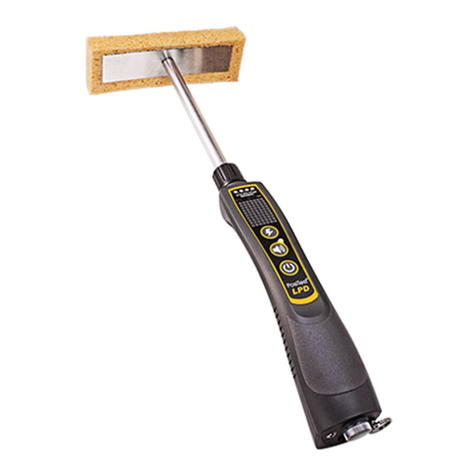
DeFelsko PosiTest LPD User manual

Introduction
Introduction
The PosiTest Low voltage Pinhole (Porosity) Detector (LPD) is a
handheld electronic instrument designed to locate small defects and
discontinuities (called “pinholes” or “holidays”) in a protective
coating system applied to a conductive substrate. Fundamentally,
the PosiTest LPD consists of a power source, a ground wire, a
probing electrode (a moistened sponge) and a multi-function LED
display.
In use, an operator moves the moistened sponge (electrode) over
the coated surface. When a pinhole is encountered, current flows
from the sponge through the moisture in the hole and into the
substrate below. The current is returned to the detector through the
attached ground wire, completing the circuit and triggering audible
and visible alarms.
To perform its intended function, a coating must be applied as a
continuous film. Pinhole (holiday) detection is useful for locating
pinholes, holidays, cracks, etc. which are not readily visible. Low
voltage pinhole detectors are commonly used to inspect non-
conductive coatings thinner than 500 µm (20 mils) applied to
conductive substrates.
DeFelsko recommends that the operator read and
fully understand this manual prior to using the PosiTest LPD.
This equipment generates voltage. Accidental contact
with the electrode may result in a mild electric shock. The PosiTest
LPD operator should exercise all due care to minimize their risk of
electric shock and be aware of all relevant safety guidelines before
operating this equipment.
1
WARNING:
IMPORTANT:

2
The PosiTest LPD is available in two kit configurations, Basic and
Complete.
PosiTest LPD Basic Kit
The PosiTest LPD Basic Kit includes the following materials:
[a] PosiTest LPD detector with 3 AAA alkaline batteries (installed)
[b] 0.2 m (8”) base tube, rectangle sponge with hardware and
insulating collar (assembled)
[c] 4.5 m (15’) ground (earth) wire
[d] Detachable ground clip
Wrist Strap (not shown)
[e] Wired earbud
[f] Instruction Manual
[g] Long Form Certificate of Calibration traceable to NIST
[h] Small hard shell case

3
PosiTest LPD Complete Kit
The PosiTest LPD Complete Kit includes all materials contained in
the Basic kit plus the following:
The above items are available individually or together in
the PosiTest LPD Accessory Pack (includes items [i] to [v]). See
Accessories on pg. 8.
NOTE:
[i] 12 m (40’) ground wire with
spool
[j] Magnetic ground (earth) clamp
[k] 4.5 m (15’) hot wire (pg.10)
[l] Universal thread adapter (pg. 10)
[m] ACME thread adapter (pg. 10)
[n] oller sponges with hardware
(pg. 10)
[o] 0.3 m (1’) Extension tube (2)
[p] Extension adaptor
[q] Carabiner
[r] 20 cm x 20 cm (8” x 8”) flat
customizable sponge (pg. 11)
[s] ound washers (pg. 11)
[t] Hook & loop fastener wire
ties
[u] Wetting agent
[v] Large hard shell case

4
Assembly Instructions
Assembly Instructions
The base tube and rectangular sponge arrive pre-assembled in both
the PosiTest LPD Basic and Complete kits.
To attach the base tube to the detector body, perform the following
steps:
1. Slide the connector end of the base tube onto the threaded
electrode connector on the PosiTest LPD.
2. Check the alignment of the rectangular sponge and rotate to a
horizontal position.
3. Move the insulating collar to the base of the tube, engage it
with the threaded electrode connector and firmly tighten the
insulating collar.
The materials included with the PosiTest LPD Complete
kit (pg. 3) provide an operator with a wide variety of assembly
options for different inspection situations.
PosiTest LPD (bottom panel)
NOTE:
Threaded electrode connector
Base tube
Insulating collar
Battery compartment
Headphone jack
Ground (earth) wire jack
Carabiner / wrist strap
loop

5
Operating Instructions
Operating Instructions
The PosiTest LPD is typically used on coatings with a measured
thickness less than 500 µm (20 mils). Before performing an
inspection, ensure that the coated surface is fully cured, dry and
free of contaminates.
1. Use clean tap water to wet the test sponge. Squeeze excess
water from the sponge until it no longer drips.
If testing a coating thicker than 250 µm (10 mils), adding a
wetting agent or other low-sudsing surfactant to the water will
reduce the surface tension of the water and promote flow into
discontinuities.
2. Connect the ground (earth) wire clip to an uncoated point of
the part to be tested. Plug the ground wire into the ground wire
jack at the bottom of the PosiTest LPD.
3. Press the Power button to power-up the unit. A self-test is
performed on power-up (pg. 6).
If not using the supplied earbud, press the Audio Alarm
button to activate the audible alarm.
4. Use the Voltage Selector button (pg. 7) to set the required
test voltage.
5. Check correct operation and alarm status by touching the
sponge to the ground clamp or another uncoated point on the
part. This should complete the electrical circuit and trigger the
LED and audio alarms. If no alarm is noted, check all
connections, wires, battery life indicator and sponge wetness.
6. Place the sponge on the coated surface and ensure the
GroundSense™ coupled indicator LED (pg. 7) remains
illuminated and does not blink. If the LED blinks, do the
following:
• Check the ground wire connections at the ground clamp and
detector.
• Attach the ground clip to a different uncoated area on the
part.
TIP:
TIP:

7. Move the sponge over the coated surface at a maximum rate of
0.3 m/s (1 ft/s) and apply sufficient pressure to maintain a wet
surface. If the sponge contacts a pinhole in the coating, all
display LEDs will illuminate and an alarm tone will sound. Alarm
will stop when the sponge is moved away from the pinhole.
8. Precisely locate the pinhole by using a corner of the sponge.
Sponge life depends on use and the abrasive nature of the
surface being tested. Replacement sponges are available with a
comprehensive selection of Accessories (see pg. 8)
PosiTest LPD Control Panel
Buttons:
Power
• Press once to power-up the detector. A self-
test of the 4 test voltages is performed. This
is indicated by a fast flash of each voltage
setting indicator. The self-test should take
approximately 2 seconds to compete. If the
self-test fails, the detector will flash all the
LEDs, sound the alarm then power off.
To conserve battery life, the PosiTest
LPD automatically turns OFF after 5 minutes of no
activity.
•Press and briefly hold to check the battery
status on the LED display.
•Press and hold for 3 seconds to power-down.
Selected Voltage and Audio Alarm settings
are retained.
The self-test can fail if performed while
the sponge/base tube is in contact with a
grounded surface.
6
NOTE:
NOTE:
NOTE:

7
Voltage Selector
• Press repeatedly to cycle through the 4 test voltage settings.
The LED display indicates the currently selected voltage.
Audio Alarm
• Press once to enable the audible alarm, press again to disable.
A green LED illuminates next to the Audio Alarm button when
the alarm is enabled.
The headphone jack is always active.
LED Display:
The four LEDs at the top of the PosiTest
LPD serve multiple functions:
1. Voltage indication
(9V, 67.5V 80KΩ, 67.5K 90KΩ, 90V)
2. Battery state indication – Press and briefly hold the Power
button to check battery status. New, fully charged batteries will
illuminate all four LEDs. Batteries should be changed/recharged
when only one LED illuminates (pg. 12).
3. Pinhole/holiday indication – When a discontinuity is detected,
all LEDs illuminate.
4. Voltage self-test on power-up – See Power button (pg. 6)
5. GroundSense - Successful low voltage pinhole detection
requires that the detector be grounded (earthed) to the test
substrate. If not properly grounded, or if the connection to
ground is lost, the detector will not alarm when a pinhole is
encountered. GroundSense is designed to assure the PosiTest
LPD operator that the detector is grounded while testing.
• The selected voltage LED stays lit when the wet sponge on the
PosiTest LPD is in contact with the coated surface and the
detector is properly grounded.
• When the wet sponge is removed from the coated part, or if the
connection to ground is lost, the selected voltage LED will blink.
NOTE:

8
For example, when a PosiTest LPD operator prepares to test for
coating pinholes on a steel beam he/she first connects the ground
clamp and 4.5 m (15’) ground wire to an uncoated area of the beam.
When the detector is powered-up, GroundSense causes the LED
for the selected voltage to blink until the operator couples the wet
sponge by placing it on the coated beam. When the wet sponge is
lifted from the coated beam, GroundSense causes the LED for the
selected voltage to blink. The LED will also blink if the ground clamp
is accidentally removed from the beam while the wet sponge is in
contact with the beam.
If the 12 m (40’) ground wire is laid near a conductive (i.e.
concrete or metal), grounded surface during testing, it may cause
GroundSense to falsely indicate a coupled condition after the wet
sponge is removed from the coated part. If GroundSense indicates
a coupled condition before the operator contacts the wet sponge to
the coated surface, its indications should be ignored. GroundSense
is for advisory use only, and does not replace the operator’s
responsibility to ensure that the detector is properly grounded.
Accessories
Accessories
A variety of accessories are available to help you get the most out
of your PosiTest LPD.
For a complete list of accessories see: www.defelsko.com/lpd
Item Order Code
Rectangular sponges (3) LPDSPONGESPK
Roller sponges (12) LPDSPONGERPK
20 cm x 20 cm (8” x 8”) flat
customizable sponge LPDSPONGECPK
Wetting agent (2) LPDWET
Accessory Pack - contains items
[i] to [v] as shown on pg. 3 LPDACCPK
NOTE:

9
Customization Options
(using items included with PosiTest LPD Complete kit or
Accessory pack)
Roller Sponge
The roller sponge may be preferred when testing over a large
surface area.
Attach the roller sponge to the base tube and PosiTest LPD.
1. Remove the rectangular sponge from the base tube (if
connected) by rotating it counterclockwise.
2. Attach the roller sponge to the base tube by rotating it
clockwise until tight.
3. Connect the base tube to the PosiTest LPD.
Replacement sponges are available (see Accessories, pg. 8)
Extending the length of the base tube
Extension Tubes
Extend the base tube an additional 0.6 m (2’) using the (2)
extension tubes.
Threaded electrode connector
Roller sponge
Base tube
Insulating collar
Base tube
Extension tube
Rectangular sponge

Extension Poles (paint roller pole / broom handle)
Attach to ACME threaded extension poles using ACME Thread
adapter or most others by using the Universal Thread adapter.
Connect the hot wire and insulating collar to PosiTest LPD.
10
Connect the
hot wire to the
extension adapter
Roller sponge
Extension adapter
ACME thread adapter
ACME threaded extension pole
Other extension poles
Universal thread adapter
Hook & loop
fastener wire ties
Hot wire
Threaded electrode connector
Insulating collar

Create a Custom Sponge
Create a Custom Sponge
Create your own custom sponge shape using the included 20 cm x
20 cm (8” x 8”) flat sponge sheet.
1. Draw your custom shape on the dehydrated sponge and cut it
out. Be sure to cut a hole in the center for connecting to the base
or extension tube.
2. Use clean tap water to wet the custom sponge. Squeeze excess
water from the sponge until it no longer drips.
3. Connect the sponge to the base/extension tube using the two
round washers.
Calibration and Verification
Calibration and Verification
Calibration
The PosiTest LPD is shipped with a Certificate of Calibration
showing traceability to a national standard. For organizations with
re-certification requirements, the PosiTest LPD may be returned at
regular intervals for calibration. DeFelsko recommends that our
customers establish their instrument calibration intervals based
upon their own experience and work environment. Based on our
product knowledge, data and customer feedback, a one year
calibration interval from either the date of calibration, date of
purchase, or date of receipt is a typical starting point.
Verification
A PosiTest LPD Verifier is available for verifying the accuracy of
PosiTest LPD detectors and is an important component in fulfilling
both ISO and in-house quality control requirements. Learn more at:
www.defelsko.com/lpd/verifier.
11

12
Battery Status / Replacement
Battery Status / Replacement
Press and briefly hold the Power button to
check battery status.
New, fully charged batteries will illuminate all four
LEDs. Batteries should be replaced/recharged
when only one LED illuminates. Replace with 3
AAA alkaline batteries as shown.
Technical Data
Technical Data
Specifications:
Sensitivity:
9V (±5%) 90K (±3%)
67.5V (±5%) 80K (±3%)
67.5V (±5%) 90K (±3%)
90V (±5%) 400K (±3%)
Thickness Range: 0 – 500 μm (0 – 20 mils)
Battery Life: > 150 hrs (Depending on battery type used)
Temperature Range: -10° to 50°C (50° to 120°F), 0 to 100% RH
Headphone: 3.5 mm mono 16-32 ohm
Battery Type: 3 AAA alkaline or rechargeable
IP Rating: Meets or exceeds IP65
Conforms To:AS 3894.2, ASTM D-5162 A, ASTM G6, ASTM G62-
A, BS 7793-2, ISO 8289 A, ISO 14654, IS K 6766, NACE SP 0188,
NACE TM 0384.
This device complies with part 15 of the FCC Rules. Operation is
subject to the following two conditions: (1) This device may not
cause harmful interference, and (2) this device must accept any
interference received, including interference that may cause
undesired operation.

13
Returning for Service
Returning for Service
Before returning the PosiTest LPD for service –
1. Install new or fully recharged batteries in the proper alignment.
2. Examine all wires, plugs and connectors for damage.
3. Ensure the test sponge is properly moistened.
4. Re-attempt measurement.
If you must return the PosiTest LPD for service,
please fill out and include the Service Form located at
www.defelsko.com/support with the detector. Be sure to also include
your company name, company contact, telephone number and fax
number or email address.
Limited Warranty, Sole Remedy
Limited Warranty, Sole Remedy
and Limited Liability
and Limited Liability
DeFelsko's sole warranty, remedy, and liability are the express
limited warranty, remedy, and limited liability that are set forth on its
website: www.defelsko.com/terms.
www.defelsko.com
© DeFelsko Corporation USA 2016 All Rights Reserved
This manual is copyrighted with all rights reserved and may not be
reproduced or transmitted, in whole or part, by any means, without written
permission from DeFelsko Corporation.
DeFelsko and PosiTest are trademarks of DeFelsko Corporation registered
in the U.S. and in other countries. Other brand or product names are
trademarks or registered trademarks of their respective holders.
Every effort has been made to ensure that the information in this manual is
accurate. DeFelsko is not responsible for printing or clerical errors.
IMPORTANT:

Introducción
Introducción
El Detector Low voltage Pinhole (porosidad) o LPD de PosiTest es
un equipo electrónico portátil diseñado para localizar pequeños
defectos y discontinuidades (llamados agujeros o poros) en un
sistema de capa protectora aplicada a un substrato conductivo.
Fundamentalmente, el PosiTest LPD consiste en una fuente de
energía, un cable de tierra, un electrodo con sonda (tipo esponja
húmeda) y una pantalla LED multifuncional.
Para utilizarla, un operador deberá mover la esponja humedecida
(electrodo) sobre el revestimiento de la superficie. Cuando se
encuentre un poro, la corriente fluirá desde la esponja a través de
la humedad por el orificio y hacia el substrato inferior. La corriente
volverá al detector a través del cable de tierra conectado al sustrato,
completando el circuito y activando las alarmas sonoras y visuales.
Para realizar su función deberá aplicarse una capa a modo de
película continua. La detección de poros (holiday) es útil para la
localización de porosidades, discontinuidades o grietas que no son
fácilmente visibles. Los detectores de poros de baja tensión se
utilizan comúnmente para examinar revestimientos de menos de
500 μm (20 mils) aplicados a substratos conductivos.
DeFelsko recomienda que el operador lea y
entienda completamente este manual antes de utilizar el PosiTest
LPD.
1
IMPORTANTE:

2
Este equipo genera voltaje. El contacto
accidental con el electrodo puede generar una descarga eléctrica
suave. El operador de PosiTest LPD deberá actuar con el debido
cuidado para minimizar el riesgo de descarga eléctrica y estar al
tanto de todas las pautas de seguridad antes de operar con este
equipo.
El PosiTest LPD está disponible en dos configuraciones de
equipo: Básico y Complete.
Equipo básico del PosiTest LPD
El equipo básico de PosiTest LPD incluye los siguientes
materiales:
[a] Detector PosiTest LPD con 3 pilas alcalinas AAA (incluidas)
[b] Tubo base de 0.3 m (1ft), Esponja rectangular con conector y
arandela aislante (ensamblado)
[c] Cable de puesta a Tierra (ground) de 4,5 m (15ft)
[d] Caimán desmontable para puesta a tierra
[e] Auricular con cable
[f] Manual de usuario
[g] Certificado de calibración de formato extenso trazable a NIST
[h] Estuche rígido pequeño
ADVERTENCIA:

3
Equipo completo de PosiTest LPD
El PosiTest LPD Complete incluye todos los materiales
contenidos en el equipo básico más los siguientes:
Los artículos mencionados anteriormente están
disponibles individualmente o en grupo en el Paquete de accesorios
PosiTest LPD (incluye artículos de [i] a [v]). Consulte accesorios
en Pág. 10.
[i] Cable de tierra de 12 m (40 ft)
con carrete
[j] Pinza de tierra con base
magnética
[k] Cable vivo de 4,5 m (15 ft)
(Pág. 11)
[l] Adaptador de rosca Universal
(Pág. 11)
[m] Adaptador de rosca ACME
(Pág. 11)
[n] Rodillos de esponja con
conector (Pág. 11)
[o] Tubo de extensión de 0,3
m (1') (2)
[p] Adaptador para extensión
[q] Gancho tipo Mosquetón
[r] Esponja plana
personalizable 20 cm x 20 cm
(8 "x 8") (Pág. 12)
[s] Arandelas redondas,
(Pág. 12)
[t] Abrazaderas de velcro
para cables
[u] Agente humectante
[v] Estuche rígido amplio
NOTA:

4
Instrucciones de montaje
Instrucciones de montaje
La esponja rectangular y el tubo de base salen de fábrica pre-
ensamblados, tanto en el PosiTest LPD Base como en el
Complete.
Para colocar el tubo de base en la base del detector siga estos
pasos:
1. Deslice el extremo del conector del tubo de base dentro del
conector de electrodo roscado del PosiTest LPD.
2. Verifique la alineación de la esponja rectangular y gire hasta la
posición horizontal.
3. Mueva el collarín aislante hacia la base del tubo, únalo con el
conector de electrodo roscado y apriete firmemente el collarín
aislante.
Los materiales incluidos en el equipo PosiTest LPD
Complete (Pág. 4) proporcionan al operador una amplia variedad
de opciones de montaje para las diferentes situaciones de la
inspección.
PosiTest LPD (panel inferior)
NOTA:
Enrosque el conector de electrodo
Tubo de base
La arandela aislante
Compartimiento de batería
Conector para
auriculares
Conector de cable de masa (tierra)
Mosquetón

5
Instrucciones de uso
Instrucciones de uso
El PosiTest LPD se utiliza normalmente en revestimientos con un
espesor medido de menos de 500 μm (20 mils). Antes de realizar
una inspección, asegúrese de que el revestimiento de superficie
está completamente curado, seco y sin contaminantes.
1. Utilice agua limpia para mojar la esponja de la prueba. Exprima
el exceso de agua de la esponja hasta que no gotee.
Si se realizan pruebas en revestimientos de más de
250 μm (10 mils), agregue un agente humectante u otro surfactante
de baja espuma en el agua para reducir la tensión superficial del
agua y facilitar el flujo en discontinuidades.
2. Conecte la abrazadera del cable de tierra a un punto sin
recubrimiento de la pieza que desee comprobar. Conecte el
cable de tierra al conector de tierra en la parte inferior del
PosiTest LPD.
3. Pulse el botón de encendido para arrancar la unidad. Se
realizará una prueba automática (Pág. 7).
Si no utiliza el auricular suministrado, pulse el botón
de alarma de Audio para activarla.
4. Utilice el botón selector de voltaje (Pág. 8) para configurar
el voltage de prueba requerida.
5. Compruebe el correcto funcionamiento y la alarma presionando
la esponja directamente contra la pinza de tierra o en algún punto
sin recubrimiento en la pieza. Esto completará el circuito eléctrico
y accionará la LED y las alarmas sonoras. Si no se observa
ninguna alarma compruebe todas las conexiones, cables, estado
de la batería y la humedad de la esponja.
6. Coloque la esponja sobre el revestimiento de superficie y
asegúrese de que el indicador GroundSense™ (Pág. 9) se
mantiene encendido y no parpadea. Si la LED parpadea, haga
lo siguiente:
• Compruebe las conexiones de cables de masa en la pinza y el
detector.
CONSE O:
CONSE O:
Other manuals for PosiTest LPD
1
This manual suits for next models
1
Table of contents
Languages:
Other DeFelsko Security Sensor manuals
Popular Security Sensor manuals by other brands

Guardian Fall Protection
Guardian Fall Protection 42001 instruction manual
Zeiss
Zeiss 4QBSD instruction manual
Inovonics
Inovonics EE1261 installation instructions

nest
nest Detect user guide

Huazheng Electric Manufacturing
Huazheng Electric Manufacturing HZJF-9008 user manual
Gewiss
Gewiss CHORUS GW 13 756 installation instructions


