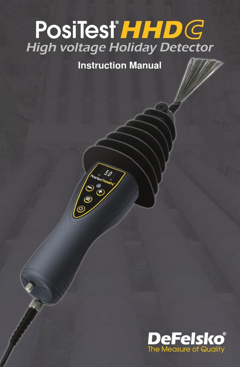
DeFelsko PosiTest High voltage Holiday Detector User manual

Instruction Manual v. 1.0
High voltage Holiday Detector


Introduction
1
The PosiTest High voltage Holiday Detector (HHD) is a Pulse
Type DC Holiday Detector designed to locate small defects and
discontinuities (called “pinholes” or “holidays”) in a protective
coating system applied to a conductive substrate. High voltage
holiday detectors are commonly used to inspect non-conductive
coatings thicker than 500 µm (20 mils).
Designed for maximum versatility, the
PosiTest HHD
can be used
in either a stick-type or wand-type configuration (when used with the
optional wand accessory). www.defelsko.com/manuals/hhd
The PosiTest HHD has two primary operating modes:
1.Standby Mode: The detector is powered-up but not generating
a high voltage.
2.Detection Mode: The detector is generating a high voltage and
analyzing electrode voltage and current to determine if holidays
are present. Holidays can be detected when the charged
electrode is passed over the coated surface. When a holiday is
encountered, current flows from the electrode into the substrate.
The current returns to the detector through the ground (earth)
wire, completing the circuit and triggering audible and visible
alarms. An integrated peak reading voltmeter measures and
displays the output voltage on the display while in use.

This equipment generates high voltages up
to 35,000V (35kV). Accidental contact with the electrode may result
in an electric shock. Always keep the working end of the electrode
away from your body and never touch it when activated. The
PosiTest HHD operator should exercise all due care to minimize
their risk of electric shock and be aware of all relevant safety
guidelines before using this equipment. When in Detection Mode
(pg. 1) generating high voltage or if an arc is being produced, the
PosiTest HHD will generate broadband Radio requency
emissions. Care must be observed in the vicinity of sensitive
electronics or radio equipment.
2
Operational Safety
De elsko recommends that the operator read and
fully understand this manual prior to using the PosiTest HHD.
IMPORTANT:
WARNING:
or safe PosiTest HHD operation:
DO NOT —
wUse in wet or rainy conditions.
wUse if you are fitted with a pacemaker.
wUse without first connecting the ground (earth) cable.
wTouch or allow anyone else to touch the object being tested.
!
DO —
wEnsure that all connections are secure and tight.
wWear appropriate gloves and footwear
wUse flagging tape and signage to keep other personnel away
from the testing area.
wCommunicate the hazards associated with holiday testing with
all personnel on-site via tailgate meetings or ield Level
Hazard Assessments.
wPower O the detector before touching the spring or brush.
wConfirm the testing voltage requirements and ensure this is
communicated to all personnel involved or working in the area.

3
The PosiTest HHD Kit contains the following materials.
APosiTest HHD
B 50 cm (20”) Extension Rod & Thumb Screw
C Stainless Steel an Brush
D 7.6 m (25’) Ground (earth) cable with Ground Clip
E Shoulder Strap
Li-ion Battery Pack with built-in charge state indicator
G Smart Battery charger with universal AC voltage input
H Pelican Storm Case [accommodates rolling spring electrode
for inspecting pipes up to 64 cm OD (25”) and brushes up to
90 cm (36”)]
PosiTest HHD Kit
A variety of optional and replacement accessories are available to
help you get the most out of your PosiTest HHD.
See www.defelsko.com/hhd to learn more.
Accessories
AD
E
CB
H
G

4
PosiTest HHD Overview
Speaker
Strobe alert
LCD display
Control panel
Madein USA
Li-Ion Battery
High voltage Holiday Detector
Madein USA
www.defelsko.com
e
a
f
b d
k
g
h
i
j
l
c
Not Shown
Shoulder Strap
Pelican Case
a an brush
bThumb screw
cAnti-rotation tab
dShoulder strap attachment points
eExtension rod
fLock gate for extension rod
gBattery compartment
hBattery
iBattery cover
jSafety trigger
kGround cable socket
lGround cable

5
Quick Start
The PosiTest HHD powers-up when the power button is
pressed. To preserve battery life, it powers-down after
approximately 5 minutes of no activity. Alternatively, select from
the menu for immediate power-down. All settings are retained.
1. Review Operational Safety (pg. 2)
2. Assemble the detector for the application to be tested –
“Assembly Instructions” (pg. 5).
3. Properly ground the instrument – “Grounding” (pg. 6).
4. Set the test voltage – “Adjusting the Test Voltage” (pg. 7).
5. Confirm that the detector is in proper working condition –
“Operational Check” (pg. 6).
6. Perform the test – “Instrument Operation” (pg. 9).
Assembly Instructions
STEP 1. Attach the Extension Rod: Press and hold the lock gate
button while inserting the rod. Ensure the anti-rotation tab on the rod
is aligned with the corresponding receptacle on the PosiTest HHD.
Release the lock gate button and ensure the rod is securely
attached.
STEP 2. Attach the Electrode: Loosen the thumb screw on the free
end of the extension rod, attach the required electrode (or adaptor),
and re-tighten the thumb screw.
STEP 3. Attach the Ground Cable: Align the flat side of the cable
connector pin with the alignment mark in the ground cable socket on
the detector, insert fully and rotate the connector clockwise 180° to
secure the cable. Rotate the cable connector 180° counter-
clockwise to unlock and remove the ground cable. (see
“Grounding”
pg. 6
)
STEP 4. Attach the Shoulder Strap: Clip the strap to the strap
attachment points.
STEP 5. Install the Battery: Loosen the screw on the battery
compartment and remove the cover. Install the battery in the correct
orientation. Replace the cover and secure with the screw.

6
Grounding
Ensure the ground (earth) cable is uncoiled and fully extended.
Connect the ground clip to an exposed (uncoated) area of the part,
or grounding rod. If no ground is available, a trailing ground wire,
grounding collar, or grounding mat may be used. Verify that the
instrument is properly grounded by touching the electrode to the
grounded substrate, ensuring that the audible and visual alerts are
properly triggered.
Never touch the ground cable while the detector is operating.
WARNING:
Operational Check
Prior to each use, the PosiTest HHD should be checked to ensure
it is operating correctly. This operational check ensures that the
audible and visual alerts are operating properly and the instrument
has voltage output. or Calibration and Verification see pg. 10.
Performing an Operational Check
1. Ensure the instrument and all components are assembled.
2. Visually inspect each cable and connection.
3. Press and release the power button on the top of the
PosiTest HHD
.
4. The
PosiTest HHD
should power on and display the test
voltage.
5. Press and hold the button and then activate and hold the
safety trigger on the
PosiTest HHD
to turn on the high voltage
and activate Detection Mode. The button can now be
released.
6.The
PosiTest HHD
should begin testing at the selected voltage.
The display will show the voltage being generated.
7.Touch the electrode to the bare ground wire or grounded
substrate of the part being inspected. Note the audible and
visual alerts. Repeat this step several times.
A spark may or may not be seen and heard. When
using a lower test voltage and on bright sunny days, the spark
may not be seen or heard.
NOTE:

7
8. Release the safety trigger to turn high voltage O and return
the
PosiTest HHD
to Standby Mode.
The
PosiTest HHD
is now ready to use.
Adjusting the Test Voltage
1.With the detector powered ON and in Standby Mode, press
to open the menu and then select the Voltage Set icon .
2.The detector will display the test voltage
3.Use the or buttons to adjust the voltage. The voltage
adjusts in 10V increments between 500V and 1,000V, and in
100V increments between 1kV and 35kV.
4.Select OK with the button to save the voltage and exit.
-
+
The formula and suggestions for setting voltage are
supplied as a guide. Always consult the coating manufacturer for
recommended voltage settings.
NOTE:
The inspection voltage should be obtained from the coating
manufacturer’s specification or by contacting the coating
manufacturer. Based on international standards, formulas and
tables can be used as a guide for setting voltages on various
coating thicknesses. A sample calculation from NACE International
Standard Practice SP0274-2011 is as follows:
The voltage output of the PosiTest HHD is regulated and maintains
the test voltage under normal electrode loading. When in Detection
Mode, the test voltage being generated is displayed on the
PosiTest HHD. Minor fluctuations on the display are normal during
inspection as the PosiTest HHD is regulating the test voltage.
When the electrode is connected to ground, the display will show
“---" indicating that the generated voltage is less than the minimum
of 500V.
V = 1,250 √T (mils)
V = 7,900 √T (mm)
where V = Voltage in volts
T = Thickness of coating

8
Adjustment using the built-in Voltage Calculator
The Voltage Calculator simplifies the task of setting the correct
test voltage for a particular coating system. It prompts the user to
enter the coating thickness on the part to be tested and the
standard the user is conforming to, and automatically calculates
the correct test voltage.
1. With the detector powered ON and in Standby Mode,
press to open the menu then select the Voltage
Calculator icon from the Menu
2. The gage will display a list of common international standards
3. Use the or button to highlight the desired standard
4. Press the button to select the desired standard
5. Depending on the selected standard, a Units Selection menu
may appear. If prompted, select the desired coating thickness
measurement units.
6. A thickness adjustment screen is now shown. Using the or
button, adjust the coating thickness to the maximum thickness
of the coating to be inspected.
Depending on the standard chosen, the range of
selectable coating thicknesses may be limited.
NOTE:
7. Press the button to select the thickness. The PosiTest HHD
will now calculate the test voltage based on the standard and
units selected.
-
+
-
+
10.5 1
The following standards are available when using the Voltage
Calculator:
AS 3894.1: 1, 2, 3, 4
ASTM D4787, D5162, G62
ISO 29601
NACE SP0274, SP0188, SP0490
Voltage adjustments will be retained when the PosiTest
HHD is powered O . Perform a RESET (pg. 11) to return to the
default voltage setting (1kV).
NOTE:

9
Instrument Operation
The PosiTest HHD is ready for testing only after
performing Steps 1-4 in the Quick Start (pg. 5).
IMPORTANT:
1. Press the power button to power-up the detector. The
PosiTest HHD
is now in Standby Mode (pg. 1).
2. Press the button to access the menu. Navigate using
the or buttons. Press to select.
3. Select the preferred Audio and Strobe Alarm settings (pg. 10).
4. Adjust the test voltage (pg. 7).
5. To activate the high voltage output and enable Detection
Mode, press and hold the power button and activate and
hold the safety trigger. The lightning bolt icon will appear at
the bottom of the display and the
PosiTest HHD
will show the
test voltage being generated.
6. Continue holding the safety trigger and release the power
button .
7. Move the electrode over the coated surface at a travel speed
not to exceed 0.3m/second (1ft/second) to locate defects. If a
holiday is detected, the
PosiTest HHD
will activate the strobe
and/or the audio alarm (depending upon setup).
8. Release the safety trigger to deactivate the high voltage output
and return the
PosiTest HHD
to Standby Mode (pg. 1).
-
+

10
Calibration and Verification
Calibration
The PosiTest HHD is shipped with a Certificate of Calibration
showing traceability to a national standard. De elsko recommends
customers establish calibration intervals based upon their own
experience and work environment. A detector used frequently,
roughly, or in harsh operating conditions may require a shorter
calibration interval than if used less frequently and handled with
care. Based on our product knowledge, data and customer
feedback, a one-year certification interval from either the date of
calibration, date of purchase, or date of receipt is a typical starting
point.
Verification
The PosiTest HHD includes an integrated voltmeter (crest meter,
jeep meter) which measures and displays the peak output voltage
of the detector on the LCD display. This provides the ability to
monitor the generated voltage of the PosiTest HHD to a specific
voltage within the 500V – 1,000V range in 10V steps, and 1kV –
35kV range in 100V steps. The PosiTest HHD integrated voltmeter
is accurate to +/- 5% of the generated test voltage.
The PosiTest HHD Verifier is available for verifying the accuracy
of the PosiTest HHD and other high voltage holiday detectors and
is an important component in fulfilling both ISO and in-house quality
control requirements.
Learn more at: http://defelsko.com/hhd/verifier
Audio Alarm
The PosiTest HHD has three audio alarm modes. Select the
icon from the menu to select an alarm mode.
Audio Alarm is O
The detector emits a continuous tone when high
voltage is on and a loud alarm tone when a holiday
is detected. This is the default audio alarm mode.
The detector emits a loud, continuous tone when
high voltage is on and is silent when a holiday is
detected.
Settings
The selected audio alarm mode is retained during power cycles.

11
Strobe Alarm: The PosiTest HHD uses a high-intensity
white LED to alert the operator when a holiday is
detected.
The strobe alarm can be turned ON or O :
Select the strobe icon or to toggle the strobe alarm
state. A red icon will appear on the display when the
strobe alarm is turned off.
The strobe alarm setting is retained during power cycles.
Reset: Perform a reset of the PosiTest HHD by
selecting from the Menu. A reset restores factory
settings and returns the detector to a known condition.
Settings are returned to the following:
Output voltage = 1kV
Audio Alarm = Continuous tone when high voltage is on
and loud alarm when a holiday is detected
Strobe alarm = ON
Power OFF: Select to power-down the PosiTest HHD.
All settings are retained.
Return/Exit Menu: Select to return to a previous menu
or exit the menu.
and Mode: When the optional wand accessory is used,
it may be desirable to enable Detection Mode (high
voltage output) without the need to keep the trigger
activated continuously. To activate the and Mode press
and hold the power button. Activate the trigger, then
release the trigger while continuing to hold the power
button until a lock icon is displayed on the LCD. Once
the lock icon is displayed, the power button can be
released and the PosiTest HHD will remain in Detection
Mode without the trigger needing to be activated. To
disable and Mode, press any button or activate the
trigger.
This visual alert may affect operators who
are susceptible to photosensitive epilepsy or other
photosensitive conditions.
WARNING:
Strobe
On
Strobe
Off
and Mode is not available if the test voltage is greater
than 15kV.
NOTE:

12
Battery Status, Charging and Installation
The PosiTest HHD Kit includes a removable, rechargeable lithium-
ion battery. It is recommended that the battery be charged after each
use.
The battery icon on the display will turn red with one bar remaining
when the battery is low. This indicates that the battery requires
charging.
Made in USA
Li-Ion Battery
High voltage Holiday Detector
Made in USA
www.defelsko.com
The battery also features a built-in charge state indicator. Press
the button on the battery to display the remaining power.
Battery Charging
The supplied smart battery charger has color LEDs to indicate
charge status:
One time Red/Orange/Green Self-test: Charger is ready for use.
Red/Green blinking: Battery recognition and initialization.
Orange: The inserted battery is of the correct type and is currently
being charged.
Green: The battery is fully charged and can be removed for use.
Red blinking: The battery is too hot or too cold to be charged
without damage. If the battery is too cold it will be charged as soon
as it has warmed up sufficiently. If the battery is too hot it should
be removed and allowed to cool down.
Red: The battery is damaged and cannot be recharged. Replace
it with a new battery.
The charger automatically switches between 110V and 240V AC
making it ideal for use worldwide.
The transport of Li-ion batteries is regulated. The supplied
Li-ion battery is rated at 72Wh (watt-hours) and has been
NOTE:

13
manufactured in accordance with the UN Manual of Tests and
Criteria Part III subsection 38.3. When transporting the PosiTest
HHD or shipping the battery separately, observe all local regulations.
Use care when handling the rechargeable Li-ion battery.
The battery may be damaged if dropped. NEVER use a cracked,
swollen or otherwise damaged battery. DO NOT puncture,
disassemble or modify the battery. DO NOT expose the battery to
high temperatures or dispose in fire.
CAUTION:
Storing the PosiTest HHD
When not in use, the PosiTest HHD should be stored in the supplied
Pelican Storm case.
Keep the instrument clean and dry. After use, clean the instrument
with a soft, damp cloth, then wipe dry. Do not use solvents such as
lacquer thinner, methyl ethyl ketone, etc.
Keep all electrical contacts clean.
IMPORTANT:
PosiTest HHD Troubleshooting
PosiTest HHD will not detect holidays
w
Check Electrode Connections: With the detector powered O ,
check all connections. Ensure the extension rod is fully engaged
within the barrel of the PosiTest HHD and the lock gate is
engaged.
w
Check Ground Connections: With the detector powered O ,
remove the ground cable and fully reinsert it twisting clockwise
180° until locked. Ensure the opposite end is clean and well
connected to the substrate of the coating system being
inspected.
w
Check Test Voltage: If the test voltage is too low, the PosiTest
HHD will not find holidays.
w
Reduce Travel Speed: Recommended travel speed of the
PosiTest HHD is a maximum of 0.3m/second (1ft/second). Since
the PosiTest HHD operates at a pulse repetition rate of 30
pulses per second, it is possible to miss holidays if the travel
speed exceeds the recommended maximum.
Always contact your carrier prior to shipping this
battery to ensure compliance with local regulations.
IMPORTANT:

14
PosiTest HHD turns OFF while in use
w
Check Battery: A low or defective battery will not be able to
sustain the power required to operate the PosiTest HHD. Charge
or replace the battery. To determine if the battery is defective
refer to Battery Charging (pg. 12).
hen generating high voltage, the PosiTest HHD display is
lower than the test voltage.
w
The PosiTest HHD integrated jeep/crest meter ALWAYS displays
the actual voltage being generated. Although the PosiTest HHD
will regulate the output voltage to match the test voltage, there
are circumstances when it is not possible to generate the test
voltage. or example, overloading of the electrode by setting the
voltage higher than recommended for the coating system under
inspection may result in a generated voltage lower than the test
voltage. Reducing the brush or electrode size will also reduce
loading.
Accessories
A variety of optional accessories are available to help you get the
most out of your PosiTest HHD.
w
Handheld Wand w/ 1.5m (5’) Insulated Cable
w
10cm (4”) Conductive Rubber Paddle
w
Steel lat Wire Brushes
w
Steel Rolling Spring Electrodes
w
Rolling Spring Electrode Connector
w
Rolling Spring Coupler (sold in pairs)
w
15cm (6”) Extension Rod for use in areas of limited
clearance/headroom
w
PosiTest HHD Verifier (Calibrated peak reading voltmeter can
be used to verify operation of the PosiTest HHD.)
w
Tinker & Rasor Electrode Adaptor
w
PCWI Electrode Adaptor
or a complete list of accessories see: www.defelsko.com/hhd

15
Technical Data/Specifications
Applicable Standards: AS 3894.1, ASTM D4787,
ASTM D5162, ASTM G62, ISO 29601, NACE SP0274,
NACE SP0188, NACE SP0490.
The PosiTest HHD meets the Electromagnetic
Compatibility Directive and Low Voltage Directive
when operated in Standby Mode.
wType: Pulse DC (30Hz)
wRange: 500 – 35,000V
wResolution: 500 – 1,000V in 10V increments, 1kV – 35kV in
100V increments
wOutput Accuracy: +5%
wOperating Temperature Range: -20° to 60° C (-4° to 140° )
wBattery: Rechargeable Smart 72Wh Li-ion battery
wCharge Time: 3 hours
wLife: Depends on test voltage and electrode load
wTypical Life: Ø 12” Rolling Spring @ 10kV, 40 hours
Ø 40” Rolling Spring @ 10kV, 30 hours
weight: 1.8 kg (4 lbs.) with battery (no electrodes)
wDimensions (no attachments):64 cm x 6.4 cm x 13 cm
(25” x 2.5” x 5”)

Limited arranty, Sole Remedy
and Limited Liability
www.defelsko.com
© 2019 De elsko Corporation USA
All Rights Reserved
This manual is copyrighted with all rights reserved and may not be reproduced or transmitted,
in whole or part, by any means, without written permission from De elsko Corporation.
De elsko, PosiTest, PosiTector, and PosiSoft are trademarks of De elsko Corporation
registered in the U.S. and in other countries. Other brand or product names are trademarks
or registered trademarks of their respective holders.
Every effort has been made to ensure that the information in this manual is accurate.
De elsko is not responsible for printing or clerical errors.
Before returning the PosiTest HHD for service –
1.Install a fully charged battery in the correct orientation.
2.Inspect all wires, plugs, and connectors for damage.
3.Power up PosiTest HHD by pressing the power button .
4.Reset the PosiTest HHD (See pg. 11).
5.Press and hold power button while activating the trigger.
6.Connect end of extension rod to ground (earth) lead to
simulate a holiday.
7.If the PosiTest HHD does not activate the Audio and Strobe
alarms or create an arc, remove the battery and return the
PosiTest HHD without the battery for service.
IMPORTANT:
If you must return the PosiTest HHD for service,
please follow the instructions provided at
https://www.defelsko.com/service-support#Service
De elsko's sole warranty, remedy, and liability are the express
limited warranty, remedy, and limited liability that are set forth on
its website: www.defelsko.com/terms
Returning for Service

Manual de instrucciones v. 1.0
High voltage Holiday Detector
Detector de Porosidad de Alto Voltaje

Introducción
El Detector de porosidad de alto voltaje PosiTest (HHD del inglés
“High-voltage Holiday Detector”) es un detector de corriente
directa (CD) por pulsos diseñado para localizar pequeños defectos
y discontinuidades (llamados porosidades o “holidays”) en un
sistema de recubrimientos protectores aplicados a un substrato
conductivo. Los detectores de porosidad de alto voltaje se utilizan
de manera habitual en inspecciones de recubrimientos no
conductores con espesor superior a 500 µm (20 mils).
Diseñado para una versatilidad máxima, el PosiTest HHD puede
utilizarse tanto en configuración tipo bayoneta o con extensión y
maneral (cuando se utiliza con el accesorio de maneral opcional).
www.defelsko.com/manuals/hhd
El PosiTest HHD tiene dos modos de funcionamiento principales:
1.Modo de esper : El detector está encendido pero no genera
alto voltaje.
2.Modo de detección: El detector está generando un alto voltaje
y simultáneamente analiza la corriente y voltaje en el electrodo
para determinar si hay presencia de poros. Los poros pueden
detectarse cuando el electrodo cargado se desliza sobre la
superficie revestida. Cuando se encuentra un poro, la corriente
fluye desde el electrodo hacia el sustrato. La corriente volverá al
detector a través del cable de tierra (ground), completando el
circuito y activando las alarmas sonoras y visuales. Un voltímetro
integrado de lectura de pico medirá y mostrará el voltaje de
salida en la pantalla mientras esté en uso.
1
This manual suits for next models
1
Table of contents
Languages:
Other DeFelsko Security Sensor manuals
Popular Security Sensor manuals by other brands

Guardian Fall Protection
Guardian Fall Protection 42001 instruction manual
Zeiss
Zeiss 4QBSD instruction manual
Inovonics
Inovonics EE1261 installation instructions

nest
nest Detect user guide

Huazheng Electric Manufacturing
Huazheng Electric Manufacturing HZJF-9008 user manual
Gewiss
Gewiss CHORUS GW 13 756 installation instructions
