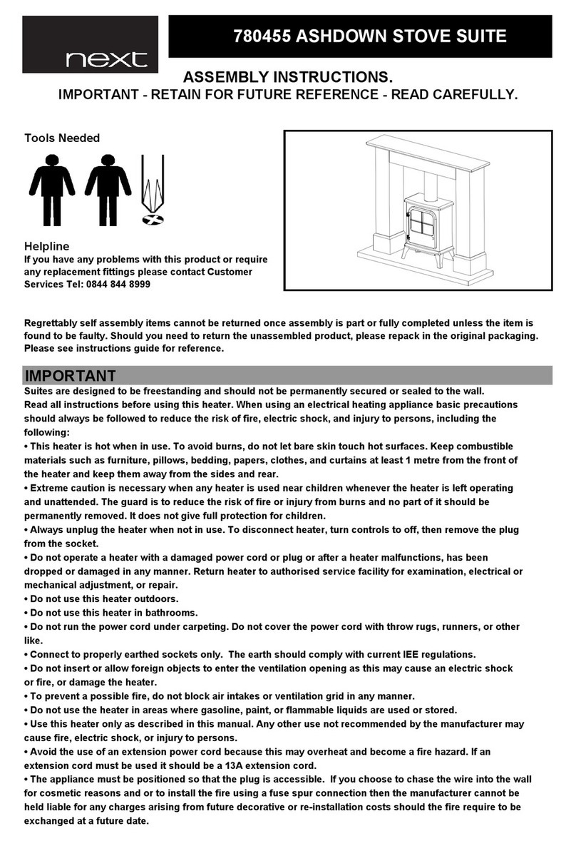
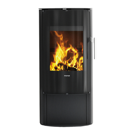
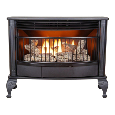
Defro Home CUBE Series User manual

operating manual
dry stove
DEFRO HOME CUBE series
Translation of original operating manual
Issue 8
June 2020

2
DEKLARACJAZGODNOŚCIWE
DECLARATIONOFCONFORMITYEC
nr57/R‐2/01/2017
DEFROSpółkazograniczonąodpowiedzialnościąSpółkakomandytowa
00‐403Warszawa,ul.Solec24/253
Manufacturingplant:
26‐067Strawczyn,RudaStrawczyńska103A
DEKLARUJE/DECLARES
zpełnąodpowiedzialnością,żeprodukt/withallresponsibility,thattheproduct
Pieckominkowywolnostojącyzręcznymzasypempaliwa/DryStovewithFuelCharge
DEFROHOMECUBE10kW
(typ/typeDEFROHOMECUBE)
zaprojektowany,wyprodukowanyiwprowadzonynarynekzgodnieznastępującymidyrektywami:
hasbeendesigned,manufacturedandplacedonthemarketinconformitywithdirectives:
został
RozporządzenieParlamentuEuropejskiego/RegulationoftheEuropeanParliament305/2011
RozporządzenieKomisji(UE)/CommissionRegulation(EU)2015/1185
iniżejwymienionyminormamizharmonizowanymi:
andthatthefollowingrelevantStandards:
PN‐EN13240:2008
dokumentacjatechniczna/technicaldocumentation
Wyróboznaczonoznakiem:
Producthasbeenmarked:
Tadeklaracjazgodnościtraciswąważność,jeżeliwpiecuwolnostojącymDEFROHOMECUBEwprowadzonozmiany,zostałprzebudo‐
wanybeznaszejzgodylubjestużytkowananiezgodniezinstrukcjąobsługi.Niniejszadeklaracjamusibyćprzekazanawrazzpiecemwol‐
nostojącymwprzypadkuodstąpieniawłasnościinnejosobie.
ThisDeclarationofConformitybecomesinvalidifanychangeshavebeenmadetotheDEFROHOMECUBEDryStove,ifitsconstructionhas
beenchangedwithoutourpermissionorifthedrystoveisusednotinaccordancewiththeoperatingmanual.ThisDeclarationshallbe
handedovertoanewowneralongwiththetitleofownershipofthedrystove.
PiecwolnostojącyDEFROHOMECUBEjestwykonywanyzgodniezdokumentacjątechnicznąprzechowywanąprzez:
DEFROHOMECUBEDryStovehasbeenmanufacturedaccordingtotechnicaldocumentationkeptby:
DEFROSpółkazograniczonąodpowiedzialnościąSp.k.,Productionplant:26‐067Strawczyn,RudaStrawczyńska103a.
Imięinazwiskoosobyupoważnionejdoprzygotowaniadokumentacjitechnicznej:MariuszDziubeła
Nameofthepersonauthorizedtocompilethetechnicaldocumentation:MariuszDziubeła
Imięinazwiskoorazpodpisosobyupoważnionejdosporządzeniadeklaracjizgodnościwimieniuproducenta:RobertDziubeła
Nameandsignatureofthepersonauthorizedtocompileadeclarationofconformityonbehalfofthemanufacturer:RobertDziubeła
Dwieostatniecyfryroku,wktórymoznakowaniezostałonaniesione:17
Twolastdigitsoftheyearofmarking: 17
Warszawa,03.07.2017
miejsceidatawystawienia
placeanddateofissue.
RobertDziubeła
prezeszarządu/CEO

3
Dear Customer,
We would like to thank you for choosing the high quality DEFRO prod-
uct, which will ensure your safety and operational reliability.
As our customers, you can always count on help of the DEFRO Ser-
vice Centre, which is ready to ensure continuous efficiency of your boiler.
Please note that in order to use the dry stove safely and efficiently, it
is crucial to get familiar with the following directions.
Get familiar with this Operating Manual - useful remarks concern-
ing proper operation of the dry stove can be found there.
Determine if all parts have been delivered or the dry stove was
not damaged during transport.
Check data on the rating plate against the warranty card.
Prior to starting the dry stove, check flue connection against con-
nection recommendations included in this manual and appropri-
ate national regulations.
Basic dry stove usage rules are to be obeyed while using the dry stove.
Do not open the doors during operation of the device.
DEFRO Service Centre or Authorized DEFRO Service should be al-
ways contacted when any intervention is necessary because only these
parties have original spare parts and are properly trained within the scope
of installation and operation of DEFRO boilers.
For your safety and boiler use convenience please get acquainted with
this operating manual and send back correctly filled copy of the Warranty
Card to the following address:
DEFRO Sp. z o.o. Sp. k. - Centrum Serwisowe
Ruda Strawczyńska 103a
26-067 Strawczyn
fax 0048 41 303 91 31
@
serwis@defro.pl
By sending back your Warranty Card, you will be registered in our DE-
FRO heating boilers users database and we will be able to provide you
quick and professional technical support.
If you do not send back a correctly filled in Warranty Card and the dry
stove quality and completeness receipt within the period of up to two weeks
after the date of installation but no longer than within six months, after pur-
chasing, the warranty will become invalid. This results in delays with re-
pairs and the necessity of covering costs of service and travelling ex-
penses.
Thank you for understanding.
Yours sincerely,
DEFRO Sp. z o.o. Sp. k.
Content of this Operating Manual is a property of DEFRO Sp. z o.o. Sp. k..
Any copying, duplicating, publishing of content of this Manual
without prior written consent of DEFRO Sp. z o.o. Sp. k. is forbidden.
Dear Customer,
We would like to inform you that we make every efforts to offer
products of quality fulfilling the most restrictive standards and warrant-
ing operational safety. All devices are produced in accordance with
the requirements of relevant EU directives and have CE safety mark
confirmed by the Declaration of Conformity EC.
We appreciate all your comments and proposals regarding our
level of service. We appreciate your comments and proposals regard-
ing our devices and the level of service provided by our Partners and
Technical Support/Service.
DEFRO Sp. z o.o. Sp. K

4
Table of Contents
1.INFORMATION.......................................................................................................................................................................................... 5
2.BASIC SAFETY RULES............................................................................................................................................................................. 5
2.1.Safety warnings ............................................................................................................................................................................... 5
2.2.Warnings related to operation........................................................................................................................................................... 6
3.INTENDED USE........................................................................................................................................................................................ 6
4.TECHNICAL SPECIFICATION................................................................................................................................................................... 6
4.1.Design............................................................................................................................................................................................. 6
4.2.Technical data ................................................................................................................................................................................. 6
4.3.Equipment ....................................................................................................................................................................................... 7
4.4.Fuel parameters............................................................................................................................................................................... 7
4.5.Spare parts...................................................................................................................................................................................... 7
5.TRANSPORT AND INSTALLATION........................................................................................................................................................... 7
5.1.Transport and storage...................................................................................................................................................................... 7
5.2.Working environment ....................................................................................................................................................................... 7
5.3.Connection to external air intake ...................................................................................................................................................... 8
5.4.Installation to flue............................................................................................................................................................................. 8
6.USAGE AND OPERATION ........................................................................................................................................................................ 9
6.1.Introductory remarks ........................................................................................................................................................................ 9
6.2.First start-up and operation .............................................................................................................................................................. 9
6.3.Damping.........................................................................................................................................................................................10
7.CLEANING AND MAINTENANCE.............................................................................................................................................................10
7.1.Basic operations and cleaning by the user.......................................................................................................................................10
7.1.1.Cleaning before each starting.....................................................................................................................................................10
7.1.2.Window panel cleaning ..............................................................................................................................................................10
7.1.3.Doors/gaskets ...........................................................................................................................................................................10
7.1.4.Furnace chamber.......................................................................................................................................................................10
7.1.5.Flue...........................................................................................................................................................................................10
7.2.Periodic inspection by authorized service.........................................................................................................................................10
7.3.Dismantling of components .............................................................................................................................................................11
7.3.1.Doors disassembly ....................................................................................................................................................................11
7.3.2.Window panel dismantling..........................................................................................................................................................11
7.3.3.Disassembly of furnace claddings ..............................................................................................................................................11
7.3.4.Change of position of flue gas outlet socket................................................................................................................................12
7.4.Shutting the stove down..................................................................................................................................................................13
8.TROUBLESHOOTING..............................................................................................................................................................................13
9.MEASURES IN CASE OF FIRE IN THE FLUE /SOOT IGNITION/..............................................................................................................13
10.REMOVAL DUE TO WEAR-OUT ..............................................................................................................................................................14
11.REMARKS ON DRY STOVE USAGE........................................................................................................................................................14
12.PRODUCT WARRANTY TERMS AND CONDITIONS................................................................................................................................14
12.1.Warranty conditions “48h Service”...................................................................................................................................................15
13.WARRANTY CARD ..................................................................................................................................................................................17
14.CARRIED OUT WARRANTY REPAIRS AND MAINTENANCE...................................................................................................................18
15.WARRANTY CARD /copy to send back/....................................................................................................................................................19
16.COMPLAINT FORM..................................................................................................................................................................................21
17.COMPLAINT FORM..................................................................................................................................................................................23
18.COMPLAINT FORM..................................................................................................................................................................................25
19.REGISTER OF INSPECTIONS OF SMOKE DUCTS..................................................................................................................................27
List of pictures
Picture 1. DEFRO HOME CUBE dry stove design................................................................................................................................................ 6
Picture 2. DEFRO HOME CUBE dry stove dimensions. ....................................................................................................................................... 6
Picture 3. Minimum safe distances during setting of dry stove. ............................................................................................................................. 8
Picture 4. Connection of the dry stove DEFRO HOME CUBE to external air intake. .............................................................................................. 8
Picture 5. Option to connect dry stove to flue. ...................................................................................................................................................... 9
Picture 6. Setting of slider for air inflow adjustment .............................................................................................................................................. 9
Picture 7. Method of fuel arrangement during firing up. .......................................................................................................................................10
Picture 8. Window panel dismantling from doors.................................................................................................................................................11
List of tables
Table 1. DEFRO HOME CUBE dry stove technical data....................................................................................................................................... 7
Table 2. Dry stove equipment.............................................................................................................................................................................. 7

5
1. INFORMATION
Operating manual is an integral and essential part of the product
and must be forwarded to the user also in case when the property is
transmitted. User should carefully read the manual and save it for the
future because all remarks included there are important guidelines con-
cerning safety during installation, usage and maintenance.
Installation of dry stove must be carried out in accordance with the
mandatory standards in country of destination, according to guidelines
of the manufacturer and by qualified personnel. Improper installation of
the device can be a reason for personal injuries and damage to prop-
erty for which the manufacturer is not liable.
Dry stove can be used only for the purpose it was explicitly in-
tended. Any other use should be treated as inappropriate and in con-
sequence as dangerous.
In case of error during installation, usage or maintenance works
caused by non-observance of the legislation, regulations in force or in-
structions contained in this manual (or others, delivered by the manu-
facturer) the manufacturer rejects any contractual or non-contractual
liability for resulting damages and the warranty for the device becomes
void.
Versions of publications
Due to continuous improvement of the product DEFRO reserves
the right to update this publication without prior notice.
Content of this Operating Manual is a property of DEFRO. Any
copying, duplicating, publishing of content of this User’s Manual without
prior written consent of DEFRO is forbidden.
Manual storage and browsing its contents
We recommend to take care about this manual and store it in easily
and quickly available location. If this manual has been lost, damaged
or destroyed you should request a copy in the sales outlet or directly
from the Manufacturer providing identification data of the product. All
the most important information included in the operating manual are
marked with “bold” and have symbols pointing out user’s attention to
hazards which can be present during operation of the dry stove. Sym-
bols used in the text are explained below:
Danger
!
Direct threat to life and health! Non-compliance with
the recommendations marked in this way and misuse
may result in death or major injuries.
Danger
!
Danger from electrical voltage! Incorrect installation
and incorrect electrical connections may cause danger
to life by electric shock.
Note
!
Warning symbol indicating that you should read care-
fully and understand the given information, to which it
relates. Non-compliance with these recommendations
may result in major damage of the equipment and cre-
ate a hazard for the user or the environment.
Danger
!
Direct threat to health! Non-compliance with the rec-
ommendations distinguished in this way may cause a
fire or burns.
Hint
!
Informative symbol. Useful information and hints are
marked in this way.
2. BASIC SAFETY RULES
2.1. SAFETY WARNINGS
The national and local provisions should be met.
Equipment should be installed in compliance with the
legal standards applicable in the given location, region
or country.
The equipment should not be used by a persons (in-
cluding children) of impaired physical, sensory, mental
capabilities and by persons without experience and re-
quired knowledge provided that such operation is no
t
carried out under their supervision or after proper in-
struction by a person responsible for their safety.
You should always observe the guidelines given in the
operating manual to ensure correct use of the equip-
ment and to prevent accidents.
Operation and adjustment should be carried out b
y
adults. Errors and incorrect setting can cause hazard-
ous situations and/or incorrect operation.
Prior to any operations the user (or any person oper-
ating the equipment) should read and understand
whole contents of this manual.
Equipment should be used only as intended. Each
other use is considered as misuse and hazardous as
a consequence.
The equipment should not be used as a ladder or ob-
ject to lean against.
Prior to installation you should make sure that the sub-
strate will resist force of the equipment considering its
weight.
In case of disturbances in operation the equipment can
be restarted only when the occurred problem has been
removed and the equipment is brought back to original
condition.
The user is fully responsible for misuse of the produc
t
and relieves DEFRO from any civil and criminal liabil-
ity.
A
ll types of modifications or replacement of equipmen
t
parts with non-original components or without authori-
zation may present a risk for operator and relieves DE-
FRO from any civil and criminal liability.
Incorrect installation or maintenance (incompatible
with contents of this manual), can cause injuries o
f
people, animals or property damage. Then DEFRO
shall be relieved of any civil or criminal liability.
Part of equipment surface is very hot (doors, handle,
window panel, flue gas discharge pipe, etc.). You
should avoid direct contact with such components
without suitable protective clothing or protective equip-
ment such as e.g. heat resistant gloves.
Do not touch the window panel after heating up of the
equipment.
Keep children away from the equipment when it is op-
erating because each hot surface can cause burns.
It is forbidden to start-up the equipment when the
doors are opened or the window panel is cracked.
Do not place and dry the underwear on the equipment.
Possible dryers for hanging underwear or simila
r
should be located at an adequate distance from the
equipment - fire hazard.
It is absolutely forbidden to open the doors if the flue
is on fire. Then call the appropriate services.
It is recommended to keep a distance min. 400 mm
between hot parts of the equipment and medium in-
flammable materials; otherwise use commerciall
y
available insulation materials. Apply this hint also fo
r
furniture, curtains etc. Minimum distances are given in
point 5.2 of the operating manual.

6
It is absolutely forbidden to use flammable liquid fo
r
equipment firing up.
If the substrate, on which the equipment is located, is
made of inflammable materials, such as parquet o
r
floor lining then you should place protective plate un-
der it (the plate should protrude 250-300 mm from fron
t
of the equipment).
2.2. WARNINGS RELATED TO OPERATION
Equipment should be shutdown in case of failure or in-
correct operation.
Fuel used in the equipment should met the conditions
described in this manual.
Internal parts of the equipment should not be washed
with water.
Do not allow contact with water and, above all, do no
t
wash any varnished coatings before curing. The coat-
ing of new devices is not an anti-corrosive coating,
heat-resistant paint only gains its protective properties
after curing under the influence of heat (after several
ignitions).
Do not expose the body to action of hot air for a long
period of time. Do not heat excessively the room
where you are staying and where the equipment is in-
stalled. It may have adverse impact on physical condi-
tion and be a reason of health problems.
Equipment should be installed in rooms with fire pro-
tection and equipped with all required components
such as supply (with air) and flue gas discharge.
Equipment and cladding made of ceramics should be
stored in rooms free from moisture and they cannot be
exposed to adverse effects of the weather.
It is not recommended to place body of the equipmen
t
directly on the floor and if such floor is made of inflam-
mable materials it should be properly insulated.
To facilitate possible interventions by the technical
personnel you should not place the equipment inside
the closed rooms and just by the walls what can als
o
disturb air intake.
A
lways make sure and check whether doors of the
combustion chamber are tightly closed when the
equipment is operating.
Equipment consumes exact amount of air which is re-
quired for combustion process; it is recommended t
o
connect the equipment for air intake from outside us-
ing suitable pipe and through special outlet located a
t
the back of the equipment.
ADDITIONA INFORMATION
In case of any problems you should contact sales out-
let or qualified personnel authorized by DEFRO. Re-
quest original spare parts if the repair is necessary.
Use only fuel with properties compatible with the rec-
ommendations of this operating manual.
Check and clean flue gas discharge ducts (connecting
piece to flue) periodically.
Store this manual carefully because it should be avail-
able for a whole period of equipment operation. In
case of sale of giving the equipment to the other use
r
you should always make sure whether the product has
the manual enclosed.
Request new copy from authorized sales outlet in DE-
FRO company if it has been lost.
3. INTENDED USE
Dry stoves are intended for combustion of wood from deciduous
trees. They are intended for heating of houses and spaces where they
are installed. They can be also used as an additional source of thermal
power.
Dry stove can be connected multiple times.
4. TECHNICAL SPECIFICATION
4.1. DESIGN
Dry stove operates as a heater for a room in which it is installed.
Hot air is emitted directly from the furnace through the window panel
and on by radiation through convection holes in the upper wall of the
device.
Body of the dry stove - walls in contact with fire - is made of galva-
nized steel sheet and furnace chamber is lined with ceramic cladding.
Body is lined with panels made of steel sheet covered with powder
paint.
Air for combustion process is supplied through the air inlet (intake)
socket located at the rear of equipment.
Socket for flue gas discharge is located in the upper wall of the
furnace. Flue gases are removed to the chimney through a flue located
in the upper wall of the dry stove.
Picture 1.DEFRO HOME CUBE dry stove design.
1 – doors with steel handle, 2 – furnace window panel, 3 – air supply
slider, 4 – doors release handle, 5 – box for wood storage, 6 – flue Φ
148 mm, 7 – steel deflector, 8 – deflector made of vermiculite, 9 –
cladding of furnace chamber, 10 – grate, 11 – drawer for ash, 12 –
adjustment of air inflow, 13 – air intake Φ124 mm.
4.2. TECHNICAL DATA
Picture 2.DEFRO HOME CUBE dry stove dimensions.
1
2
3
5
4
6
7
8
9
10
11
12
13
214,5
124
405
305
305
405
148
118
360 30
6
8
3
1269
450
448
58
680470

7
Table 1. DEFRO HOME CUBE dry stove technical data.
Specification / device type Unit DEFRO HOME CUBE
Nominal power kW 10
Heating power range kW no data
Flue size mm 148
Single fuel charging kg ~3.5
Efficiency % 70.1
Seasonal energy efficiency % 60.1
CO emission for 13% O2%
mg/m3
0.09
1173
Flue gases temperature °C 357
Weight1) kg 230±20
Flue gas stream for nominal power g/s no data
Minimum draught at rated power Pa no data
Fuel type dry hardwood tree (max. 20% of
moisture content)
Type of heater of periodic combustion
1) Device weight depends on the selected design version and its equipment.
4.3. EQUIPMENT
The dry stove is delivered on a pallet, foil-wrapped and is fully as-
sembled. The scope of delivery can include additional components and
subassemblies, according to the order of the user. Components which
are standard equipment are specified in table 2.
Table 2. Dry stove equipment.
Standard equipment of dry stove Unit Quantity
Dry stove user’s manual pcs. 1
The ceramic lining of the furnace chamber set 1
4.4. FUEL PARAMETERS
The dry stove is intended for combustion of wood from deciduous
trees (oak, hornbeam, ash, beech) with a moisture content below 20%
(wood seasoned in proper conditions for at least 2 years). The
maximum length of chunks of wood is 300 mm.
It is not allowed to use wet wood (extensive contamination of fire-
place and soot emission and a decrease of furnace energy efficiency).
It is forbidden to use all other fuels, min. coal, softwood from conif-
erous trees, wood from tropical trees and any liquid fuels.
It is forbidden to combust all types of litter and wood wastes. Firing
with inadmissible materials in the fireplace may result in damage to the
fireplace and life and health hazard for the users (toxic flue gas from
chemicals).
Use of bad quality fuel or incompatible with the abov
e
-
mentioned recommendations would cause irregulari-
ties in the operation of the equipment and can lead to
loss of warranty and decline of the liability for the
product.
The dry stove is not a furnace intended for combustio
n
of wastes and forbidden fuels cannot be combusted i
n
it.
Wood should be seasoned minimum two years. Firin
g
with wet wood, with low calorific value, decreases th
e
efficiency and has an adverse influence on dry stov
e
lifetime.
It is not recommended to use softwood and resinou
s
woods as a fuel. It causes intensive smoke concentra-
tion and the necessity to clean the equipment and flu
e
more often.
It is forbidden to combust coal, wood from tropica
l
trees, chemical products, liquid fuels etc., e.g. oil, alco
-
hol, petrol, naphthalene, laminated, impregnate
d
boards etc., paper, cardboards, old clothes, wastes.
DEFRO Sp. z o.o. Sp. k. does not accept liability fo
r
damage caused or improper burning of fuel if the fue
l
used is prohibited.
4.5. SPARE PARTS
To obtain information on the availability of spare parts for dry stove
or inquiries about equipment servicing please contact with DEFRO Ser-
vice Center or Authorized DEFRO Service.
DEFRO Sp. z o.o. Sp. k.
Service Centre
Ruda Strawczyńska 103a
26-067 Strawczyn
fax 0048 41 303 91 31
@
serwis@defro.pl
5. TRANSPORT AND INSTALLATION
5.1. TRANSPORT AND STORAGE
The dry stove is delivered on a pallet, foil-wrapped and is fully as-
sembled. It is recommended to transport dry stove, in such packing
condition, as close as a possible target location for installation, what
will minimize the possibility of damage of device housing.
All remaining parts of the packing should be removed in such a
way that it will not pose any hazard for people and animals.
Appropriate lifts are to be used for lifting and lowering the dry stove.
For transport, the dry stove is to be secured against moving and tilting
on a vehicle's platform by means of belts, wedges and wooden blocks.
The dry stove is to be transported in a vertical position
!
The dry stove is to be stored in a non-heated room, under a roof
and with efficient ventilation. Prior to installation it is to be determined
if all parts have been delivered and if they are in good technical condi-
tion.
5.2. WORKING ENVIRONMENT
The dr
y
stove should be installed in compliance wit
h
the requirements of the currently applicable standard
s
and legal regulations and detailed regulations of th
e
target country. In Poland these conditions are regulate
d
by the Regulation of the Minister of Infrastructure of 1
2
A
pril 2002 on technical conditions which should be ful
-
filled by buildings and its location. (Journal of Laws no.
75 of 2002 item 690 as amended) and Polish Standar
d
PN-13240:2008 Room heaters fired by solid fuel. Re-
quirements and tests.
The dry stove should be installed in a suitable location allowing
opening of the doors and carrying out regular maintenance works. The
environment should be:
adapted to operating conditions,
equipped with power supply 230V/50Hz,
equipped with a suitable flue gas exhaust system,
equipped with an external ventilation system,
equipped with an earthing system with CE certificate.
Correct setting of the stove is necessary to obtain the satisfactory
heating level of the residential unit. Prior to assembly it is necessary to
select a suitable position for stove installation. Check minimum safe
distances from materials susceptible to heat or inflammable materials
such as load-bearing walls and other walls or wooden components, fur-
niture etc.

8
Picture 3. Minimum safe distances during setting of dry stove.
Installation of the dry stove should observe the following safety
rules:
minimum distance 400 mm from side and rear of the medium
inflammable materials,
minimum distance 800 mm from the front wall, where the me-
dium inflammable materials cannot be located.
objects made of highly inflammable materials should be lo-
cated in distance minimum 2000 mm from the furnace
If it is not possible to maintain the above indicated distances then
you should apply process and building measures to avoid fire hazards.
In case of contact with wooden wall or wall made of other inflammable
material it is appropriate to insulate flue gas discharge pipe.
In
the
cas
e
of
the
floor
made of inflammable materials i
t
is appropriate to prepare a plane protecting the floo
r
and execute protection in accordance with the stand
-
ards applicable in the given country.
The dry stove should be located on a substrate with suitable load-
bearing capacity. In accordance with the Polish Standards each square
meter of the floor slab in the single-family building should transfer a
load of 150 kg. If this condition is fulfilled the dry stove manufactured
by DEFRO can be installed without needing to reinforce the floor slab.
Nonetheless, if you are not sure about the design of floor slab,
where the stove is to be installed, you should absolutely contact with
building designer to reinforce the floor slab or execute special structure
distributing the weight on a larger area.
Flooring in the room, where the stove is to be installed,
should be properly dimensioned, to maintain the load.
To ensure correct operation of dry stove you should ensure suita-
ble inflow of air required for combustion (it is appropriate to ensure ap-
prox. 40 m3/h) in accordance with the installation standards and stand-
ards applicable in the given country. The volume of the surrounding
environment should not be less than 30 m3. You should assume that
combustion of 1 kg of wood requires ~8 m3of air.
Air should be supplied through fixed openings of minimum 100 cm2
cross section made in the walls (near the stove) and directed to outside.
This opening should be made in a way ensuring that they cannot be
plugged.
Air can be supplied from adjacent rooms, provided that they are
equipped with external air supply and they are not intended for a bed-
room and bathroom, and where fire hazard is not present, for example:
garages, woodsheds, inflammable materials storage. You should ab-
solutely observe recommendations of the applicable standards.
It is forbidden to install
a
dr
y
stove in bedrooms, bath
-
rooms and other rooms where other heating equipmen
t
without independent air inflow are installed (fireplace,
stove, etc.).
It is also forbidden to set dry stove in explosive atmos
-
pheres.
5.3. CONNECTION TO EXTERNAL AIR INTAKE
Room, where the dry stove is installed, should be equipped with
an inflow of air in the minimum amount required for correct combustion
process and for room ventilation. This can be done by executing fixed
vents in the wall directed to the outside or through independent or com-
mon ventilation ducts.
Picture 4.Connection of the dry stove DEFRO HOME CUBE to external
air intake.
The external wall near the stove should have through the opening
with free cross-section 100 cm2(opening with 12 cm in diameter or
square 10 x 10 cm), protected with grille on the internal and external
side, for this purpose. Furthermore, the air intake should be:
directly connected with the room, where the dry stove is to
be installed,
protected with grille, metal net or suitable cover not restrict-
ing minimum cross-section,
located in a way preventing plugging it,
located with consideration of proper distances preventing
swirling of air (e.g. with respect to the windows).
5.4. INSTALLATION TO FLUE
The dry stove should be connected to the individual flue. Size of
chimney draught should equal:
minimum draught −6 ±1 Pa,
average, recommended draught −12 ±2 Pa,
maximum draught −15 ±2 Pa.
During execution of opening for flue gas discharge pipe you should
consider the possible occurrence of inflammable materials. If the open-
ing will pass through the wooden wall or wall made of material sensitive
to heat then you should obligatory maintain minimum distance from
flammable material (value given on the certification label of the pipe),
with possible additional insulation using proper materials (thickness 1.3
- 5 cm, heat conductivity min. 0.07 W/m °K).
As an alternative is it is recommended to use an insulated indus-
trial pipe, which can be also used outdoors, to avoid the occurrence of
condensate.
For correct operation connector between the dry stove and flue or
smoke duct should be executed acc. to the below recommendations:
horizontal sections should have a minimum slope 3% to-
wards the top,
D
i
s
t
a
n
c
e
f
r
o
m
f
la
m
m
a
b
l
e
m
a
t
e
rial
Distance from highly
flammable material
Protection on flooring
200 mm
400 mm
800 mm
2000 mm
400 mm
400 mm
A
ir inlet connection
(air intake)

9
length of the horizontal section should be minimum and
should not exceed 2/3 metre,
a number of changes of directions, inclusive of use of the
“T” component, should not exceed 4.
Picture 5.Option to connect dry stove to flue.
Chimney or individual smoke duct should meet the following require-
ments:
be resistant to combustion products, water-proof and suitably
insulated, in compliance with conditions of use,
be made of materials resistant to normal mechanical
stresses, heat, the action of combustion products and possi-
ble condensate,
be vertical with a change of axis direction not exceeding 45°,
be adequately separated with void space or suitable insula-
tion from combusted and inflammable materials,
have preferably circular internal cross-section: square or rec-
tangular cross-section should have rounded corners with a
radius not smaller than 20 mm,
internal cross-section should be constant, free and independ-
ent,
have a rectangular cross-section with the maximum ratio be-
tween two sides equal to 1.5.
It is forbidden to use mechanical exhaust ventilation.
The dry stove should not be used if the chimney
draught is too low.
The stove offers two locations of flue gas outlet socket: on top or
rear wall of the stove. The stove is delivered from a factory with a socket
installed in the top wall. Change of its location is described in chapter
7.3.4
6. USAGE AND OPERATION
6.1. INTRODUCTORY REMARKS
Do not touch stove during first firing
-
up, because th
e
paint is hardening during this stage.
Touching the paint could result in uncovering of stee
l
surface.
It is possible to refresh it using spray paint of the same colour if
necessary.
It is good practice to ensure efficient ventilation durin
g
first firing-up because a small amount of smoke an
d
paint odour will be emitted from the stove.
Do not stay near the stove. It is required to vent the room. Smoke
and paint odour will disappear after approx. one hour of operation.
However, we remind that they are not harmful to health.
The furnace is subject to expansion and shrinkage during warming
and cooling down stage what may cause slight squeaks. This is an
absolutely normal phenomenon because a structure of the equipment
is made rolled steel and this phenomenon shall not be considered as a
defect.
It is very important to avoid excessive overheating of the stove at
the beginning but to reach the required temperature gradually. Use low
heating powers. During the next firing-up of the stove it will be possible
to use whole available thermal power. This will avoid damage of ce-
ramic tiles, welds and steel structure.
Do not expect immediate effects of heating
!
6.2. FIRST START-UP AND OPERATION
Picture 6.Setting of slider for air inflow adjustment
Set slide of a damper for maximum opening (picture 6). Charge
approx. 1 kg of dry hardwood and fire it up. The odour of paint from the
body will be released during the first several hours of combustion. This
is completely normal. You should strongly vent the room at that time.
Check tightness of joints once again when fuel is completely burned
out and equipment has been cooled down.
Empty the ash drawer prior to each successive start-up of the
equipment. Remove grate, then ash drawer using handles, and remove
the remaining dust. Window panel should also be cleaned. Do not use
sharp materials. It will damage the surface of the window panel and
screen printing.
Do not fill the furnace completely with wood. The charge should
not exceed 1/3 of the volume of the combustion chamber. To obtain
optimum operating parameters of the equipment you should make a
single charge in an amount approximately equal to the single charge
given in table 1. Method of fuel laying is shown on figure 7
cleaning hole
rosette
diameter of
connection with flue
non-flammable
material
flu
e
mortar
rosette
diameter of
connection with flue
non-flammable
material
flu
e
mortar
cleaning hole
maximum
opening
maximum
closing

10
Picture 7. Method of fuel arrangement during firing up.
You should use only hardwood (recommended beech, oak, horn-
beam) of low moisture content (below 20%). During combustion the
doors should be opened only when the fuel is being added. Prior to
adding the wood you should wait until flames fall down and charge is
completely burnt out leaving a layer of glow facilitating firing up. After
firing up refill combustion chamber with wood, placing fuel in a way that
reasonably fills the combustion chamber for the combustion period ex-
pected by the user based on personal experience. Combustion inten-
sity should be adjusted with the air controller located on side of the
equipment.
Housing components will be very hot during operation.
You must exercise caution.
6.3. DAMPING
Damping is executed by the closing inflow of primary air. In such
case you should wait until the fuel completely burns out in a natural
way.
If it is necessary to quickly damp a flame you should charge fur-
nace chamber with dry sand or ash. It is not allowed to damp a flame
by pouring it with water because it may damage components of the
equipment.
A
fter a longer break in equipment’s operation yo
u
should check flow capacity of the flue.
7. CLEANING AND MAINTENANCE
A
ll opera
t
ions related to cleaning of all component
s
should be carried out when the stove is completel
y
cold. It is required to use protective gloves.
It is a good practice to ensure good ventilation of th
e
room during cleaning of the fireplace.
7.1. BASIC OPERATIONS AND CLEANING BY THE USER.
Any service and maintenance works are to be carried out with me-
ticulous care and only by adults familiarized with this manual. The dry
stove should not be cleaned in the presence of children.
A
ny service and maintenance works are to be carrie
d
out with meticulous care and only by adults familiarize
d
with this manual. The dry stove should not be cleane
d
in the presence of children.
7.1.1. CLEANING BEFORE EACH STARTING
Prior to every successive start-up of the equipment the ash con-
tainer should be cleaned and emptied, handling the ash with due care.
Remove grate, then ash container using handles, and remove the re-
maining dust. Dust can be removed using vacuum cleaner only if it is
completely cold. Use vacuum cleaner adapted to remove the particles
of a specified size for this purpose.
Re-install the ash container below the grate after the cleaning,
making sure that its position is correct.
7.1.2. WINDOW PANEL CLEANING
It is recommended use a dry brush to clean the ceramic glass. If
the contamination is significant use suitable cleaning agent spray and
spray little amount and then clean the window panel with a cloth.
Do not use abrasive products and do not spray th
e
p
roduct for window panel cleaning on painted parts an
d
gaskets of fireproof doors (cord made of ceramic fiber).
Do not open doors to clean the window panel durin
g
operation of the fireplace. Cleaning of window panel i
s
possible only when the equipment is cold.
7.1.3. DOORS/GASKETS
Abrasive surfaces of doors and closing mechanism should be oc-
casionally lubricated with graphite grease. Carry out inspection and
cleaning of the whole stove prior to each heating season. Pay special
attention to the condition of gaskets, replace them if necessary.
7.1.4. FURNACE CHAMBER
Clean furnace chamber of the stove periodically, depending on
moisture content and type of wood used.
7.1.5. FLUE
In compliance with applicable regulations you should clean the flue
two times a year. The flue should be cleaned by a chimneysweep com-
pany and this fact should be documented in this manual.
Flue gases coming out of blocked chimney are danger
-
ous. Chimney and connector should be kept clean.
They should be cleaned before each heating season.
A
fter a longer break in equipment’s operation yo
u
should check flow capacity of the flue.
7.2. PERIODIC INSPECTION BY AUTHORIZED SERVICE
After the heating season it is necessary to clean the chamber
through which flue gas is flowing. This cleaning is obligatory and is in-
tended to remove all combustion residues.
Periodic inspection of the equipment should be carrie
d
out only by a qualified manufacturer’s service.

11
7.3. DISMANTLING OF COMPONENTS
7.3.1. DOORS DISASSEMBLY
1. Open the doors and lift them into maximum upwards position to
remove bottom pin of the hinge from a sleeve.
2. Slide bottom edge of the doors to outside to position pin of the
hinge outside the sleeve. Remove doors in such position.
3. If it is impossible to remove hinge pin from the sleeve due to too
small clearance over the doors then you should remove the top
cover of the furnace undoing screws indicated on the above draw-
ing.
4. Then loosen screws fixing the upper wall of the stove, which is
locking the doors from the top. Repeat the operations described
in point 1 and 2 using the additional clearance.
7.3.2. WINDOW PANEL DISMANTLING
It is possible to disassemble the window panel after the doors have
been disassembled. The best way is to disassemble the window panel
when the doors are in horizontal position (e.g. when such doors lie on
the table).
Picture 8. Window panel dismantling from doors.
7.3.3. DISASSEMBLY OF FURNACE CLADDINGS
1. Open the doors. First, you should disassemble the deflector.
2. Lift one side of deflector and then lift the whole deflector upwards
in such a position. Slide it slightly to the left or right to place it in
free space between the side panels.

12
3. Lower the deflector in such position and remove through the
doors opening.
4. Lift and remove both parts of the grate.
5. Remove both side plates
6. At last, remove the plate located on the rear wall.
7.3.4. CHANGE OF POSITION OF FLUE GAS OUTLET SOCKET
1. Unscrew fixing bolts and remove the top cover of the stove.
2. Remove the screws fixing rear cover of the stove. Lift the cover
to the top and slide out with horizontal movement to outside.
3. Unscrew plug of flue gas socket located on the rear wall. Remove
plug with gasket.
4. Remove fixing screw holding a steel deflector through the open-
ing in the rear wall. Remove flue gas outlet socket with a gasket
and lay released flue’s deflector inside the furnace on a deflector
made of vermiculite.

13
5. Plug with gasket should be placed on the top wall. All correspond-
ing mounting holes should be matched. Lift flue deflector and
tighten the plug with gasket to the steel deflector using screws.
6. Move the flue gas outlet with a gasket to rear wall of the furnace
in a way ensuring that that shearing is located on the top; Tighten
screws fixing the socket.
7. Gently break off the plug (1) in rear cover of the furnace and then
slide the cover to its place. Tighten screws (2) fixing the cover to
the top wall of the stove
8. Install the top cover of the stove.
7.4. SHUTTING THE STOVE DOWN
It is recommended completely shutdown the stove and clean the
equipment when each heating season is finished.
8. TROUBLESHOOTING
Some anomalies indicating irregularities in operation can occur
during operation of the equipment. It can be caused by incorrect instal-
lation of the equipment without observation of the applicable building
regulations or provisions of this manual or by external causes e.g. nat-
ural environment.
Below you will find the most frequent causes of incorrect of the
equipment with their solutions.
Smoke draw back when the doors are opened:
the too rapid opening of the doors (open the doors slowly);
if chimney damper has been installed as a chimney draught
regulator - open the chimney damper each time when the
doors are opened;
insufficient air inflow to the room, where the equipment is in-
stalled (ensure proper ventilation in the room or supply air to
the combustion chamber in compliance with guidelines in the
manual);
atmospheric conditions: low pressure, mists and precipita-
tion, sharp changes in temperature;
insufficient chimney draught (carry out chimneysweep in-
spection of the flue).
Insufficient heating or damping:
too low amount of fuel in the furnace (charge furnace in com-
pliance with the manual);
the too high moisture content of wood used for combustion
(use wood with moisture content <20%) a large part of ob-
tained energy lost in water evaporation process:
too low chimney draught (carry out chimneysweep inspection
of the flue).
Insufficient heating despite good combustion in combustion
chamber:
low calorific “soft” wood (use wood as recommended in the
manual);
the too high moisture content of wood used for combustion
(use wood with moisture content <20%);
too fragmented wood, too thick chunks of wood:
Excessive contamination of window panel:
low intensity of combustion (combustion with very small
flame, use only dry wood as a fuel);
using resinous softwood as a fuel (use dry hardwood as a
fuel
foreseen in the stove operating manual).
Correct operation can be disturbed by an atmospheric
condition (air moisture content, fog, wind, atmospheric pressure)
and sometimes by closely located high facilities.
In case of repeated problems you should turn to chim-
neysweep company to confirm the reason of such condition and
to indicate the best solution for the problem.
9. MEASURES IN CASE OF FIRE IN THE FLUE /SOOT IGNI-
TION/.
Systematic cleaning of smoke ducts should be per
-
formed to prevent soot ignition in the chimney.
Soot ignition in the chimney is burning of particles deposited inside
chimney (flue) channels; the deposits are formed in the course of heat-
ing equipment's operation and were not cleaned by chimney sweeps.
In the case of soot fire in the chimney the following recommendations
should be observed:
1
2

14
call Fire Brigade at 998 or 112, give information about what
is happening and give detailed directions what is happening
and hot to get to the given building;
damp a fire in the chimney by the closing inflow of cold air to
the furnace chamber;
close stove's door and cleaning holes tightly to cut off air sup-
ply (due to lack of air the fire will eventually stop);
check the whole chimney channel for any cracks which might
result in fire spread to the rooms;
prepare fire quenching means, e.g. a fire extinguisher, a fire
blanket, a hose connected to the water system, water in a
container;
make rooms and necessary information available to the Fire
Brigade.
It is strictly forbidden to pour water into the chimney
-
the risk of a blowout.
Leaking chimney channels can be a source of burnin
g
sparks or very hot flue gas, including insensible carbo
n
monoxide.
Chimneysweep should be called after soot fire in th
e
chimney to perform cleaning of ducts and to inspec
t
their technical condition.
10. REMOVAL DUE TO WEAR-OUT
The dry stove is made of materials neutral for the environment.
After worn out of the stove parts connected with screws should be dis-
assembled by unscrewing and welded parts must by the cut. Elements
of a stove are subject to standard waste disposal, mostly as steel scrap.
Take safety precautions during disassembly of the equipment by using
appropriate hand-held and mechanical devices as well as personal pro-
tective equipment (gloves, clothes, apron, glasses, etc.).
11. REMARKS ON DRY STOVE USAGE
The following rules of safe operation of the dry stove
s
should be strictly observed and introduced.
1. The dry stove can be used only by adult persons, who have fa-
miliarised themselves with this operating manual and have been
trained in the scope of usage.
2. It is forbidden for children to be in the neighbourhood of the stove
without adults.
3. Flammable liquids must not be used for torching the fuel; only
solid fuel (e.g. tourist), paper can be used etc.
4. Flammable materials must not be placed on the stove and in its
vicinity.
5. It is forbidden to damp a fire in a furnace with water.
6. It is forbidden to use a furnace with cracked window panel.
7. You should use fuel recommended by the manufacturer.
8. Never stand in front of the stove door while opening. Burn risk.
9. While removing ash from the stove, flammable materials cannot
be located closer than 1500 mm from the stove. Ash is to be put
into heat-resistant containers with a lid.
10. After a heating season has finished, the stove and smoke channel
are to be precisely cleaned.
12. PRODUCT WARRANTY TERMS AND CONDITIONS
1) Placing warranty statement, which contents correspond to the
provisions of this document, the Guarantor - manufacturer of the
product - DEFRO Sp. z o.o. Sp. k. with seat in Warsaw, 00-403
Warszawa, ul. Solec 24/253, entered in the Register of Entrepre-
neurs of the National Court Register by the District Court in War-
saw for the capital city of Warsaw, XII Commercial Division of the
National Register of Entrepreneur under the number KRS
0000620901, NIP: 9591968493, REGON: 363378898, manufac-
turing plant: Ruda Strawczyńska 103A, 26-067 Strawczyn, gives
the Purchaser a warranty for the sold product on terms and con-
ditions specified below.
2) The guarantee refers to a dry stove type .................................
with serial number ............................. (the subject of agreement -
dry stove) under the condition that the product has been fully paid.
Due to suitable, proven and unified standards of sales the war-
ranty covers only product purchased in authorized points of sales
of the Guarantor or from authorized distributors. A full list of au-
thorized companies is available on the website www.defro.pl.
3) When the whole price will be paid and the product will be issued
to the user also the warranty card will be issued. In the warranty
card is missing the Purchaser should immediately contact with
the Seller to obtain this document, while its lack has no influence
on validity and period of the warranty given based on this state-
ment, but it can have an influence on correct, timely processing
of obligations resulting from this warranty by the Guarantor.
4) To allow Guarantor efficient operation the Purchaser should im-
mediately after issuance of the product, send back a copy of cor-
rectly completed Warranty Card to the address of the Guarantor
(Ruda Strawczyńska 103a, 26-067 Strawczyn). Correctly filled
Warranty Card has a date, stamp and signatures in designated
locations.
5) The Purchaser receives Warranty Terms and Conditions, War-
ranty Card as well as Operating Manual containing conditions for
boiler's usage, installation guide and parameters regarding the
chimney, fuel and boiler water.
6) The Guarantor guarantees that the equipment works correctly
provided that all conditions specified in the Operating Manual
have been met, especially with respect to parameters applying to
fuel, connection to the chimney system. The warranty covers
product used in compliance with its intended use and information
provided in the service manual. A guarantor is not responsible for
the effect of normal wear and tear of the product which is con-
nected with the operation.
7) The warranty authorizations period commences on the date of is-
suance of the product to the Purchaser and equals:
a) 5 years for correct operation of the equipment,
b) 2 years for claddings made of heat resisting concrete -
Ceramiton, while the warranty does not cover discolora-
tions, complete change of colour or deterioration of top coat,
c) 1 year for the grate, deflector and gaskets of the fireplace,
d) elements subject to wear-out are not covered by the War-
ranty; these include: ceramic hardened glass, screws, nuts,
handles etc.
8) The Warranty is valid in the Republic of Poland.
9) During the warranty period, the Guarantor ensures free-of-charge
repairs of any physical defects of the product within the period of:
a) 14 days after the fault report, unless the repair requires re-
placement of constructions elements of the product;
b) 30 days after the fault report, if the repair requires replace-
ment of constructions elements of the product;
c) subject to point 3 and 4 of this warranty conditions.
10) If, as a result of considering the warranty claim the defective prod-
uct has been replaced with new one or the significant repairs have
been made, then a new warranty period is applied counting from
the date of delivery of the replaced or repaired product. In the
case when only part, belonging to the claimed product, is re-
placed then the new warranty period is applied only for this part.
In other cases the warranty period is prolonged by a period when
the operation of the product was impossible due to a filed claim.
11) Registration of any physical fault to be repaired during the war-
ranty period (fault registration) should be made by the Purchaser
immediately after a fault has been found and no later than after
14 days.
12) Any fault is to be registered with the Guarantor (Ruda Straw-
czyńska 103a, 26-067 Strawczyn) by sending a complaint sheet
contained in this operating manual, filled in and stamped by an
authorized point of sale or authorized distributor. The fault regis-
tration should contain:

15
a) type, capacity, serial number, manufacturer number (the in-
formation is located on the rating plate),
b) date and place of purchase,
c) a brief description of the fault,
d) detailed address and phone number of Purchaser.
If the following cases are complained about: incorrect combustion
in the device, tar deposits, smoking through the door; the fault
registration should be supplemented with a copy of a chimney
sweep expertise certifying that the flue meets all requirements
specified in the operating manual for a given boiler's capacity.
13) The Guarantor shall not be responsible for exceeding of the peri-
ods mentioned in point 9 above or the Guarantor or its represent-
atives will be ready to remove the defect within the date agreed
with the Purchaser and will not be able to carry it our due to a
reasons not attributable to the Guarantor (e.g. lack of proper ac-
cess to devices, lack of energy or water, force majeure, Pur-
chaser is not present etc.).
14) If the Guarantor, despite being ready to carry the repair, will not
be able to carry out the warranty repair twice because of the rea-
sons attributable to the Purchaser then it is assumed that Pur-
chaser had resigned from the claim included in the guarantee
claim. Notification about the same defect in this mode is not pos-
sible.
15) If the fault complained about cannot be removed and after three
repairs the product is still faulty but can be used, the Purchaser
has the following rights:
a) to obtain a discounted price for the product, proportionally
to the use value of the product;
b) replace the product with one free of faults.
16) The product can be replaced if the Guarantor decides it cannot
be repaired.
17) The Guarantor does not accept liability for the inappropriate
choice of product with respect to the heated area (e.g. device of
too low or too high power with respect to requirements). It is rec-
ommended to choose a device with cooperation with a design of-
fice or the Guarantor. The Guarantor is not liable for loss of data
saved in the equipment and for economical losses and lost profits.
18) The guarantor will refuse realization of Purchaser’s claims result-
ing from this document in the case when:
a) will state damage or ripping of leaden seals,
b) identification of product will be impossible (that is conformity
of the presented product with a document describing the
equipment, replaced or illegible documents),
c) damages resulting from incorrect transport carried out or or-
dered by Purchaser,
d) particular components of the equipment were willfully re-
placed with non-genuine, used etc., repairs outside the au-
thorized service of the Guarantor etc.
e) damages are mechanical, chemical, thermal and they are
not resulting from causes in the sold product.
f) damages concerns wearing parts, especially: screws, nuts,
handles, ceramic and sealing elements,
g) damages resulting from product usage inconsistently with
the operating manual, that is especially when incorrect
equipment operation resulting from lack of chimney draught
or inappropriate power of the equipment,
h) faults are not significant and do not have an impact on the
use value of the product.
19) This warranty does not cover:
a) products used for business purposes or industrial uses;
b) components of electrical equipment;
c) damages caused by the other connected equipment, de-
vices or accessories other than these recommended by the
Guarantor.
d) damages occurred as a result action of external impacts,
among other: by the action of force majeure;
e) damages caused by animals,
20) Warranty repairs accepted by the Guarantor are carried out free
of charge. The guarantor can charge the costs connected with
warranty claim only in the case when a claim is not accepted as
a result of stating circumstances which are listed in points 17 and
18 mentioned above.
21) Notification of complaint can be considered positively only in case
of:
a) keeping the time-limits mentioned in this document;
b) fulfilling the other terms and conditions of the warranty;
c) presentation of product proof of purchase - that is an invoice
or fiscal receipt, the other proof of purchase, in compliance
with the regulations;
22) Device installation can be carried out by a person holding general
installation qualifications but an entry and stamp in the Warranty
Card are required.
23) Device's first start-up, any repairs and other activities, which are
not supposed to be carried out by the User according to the op-
erating manual, can be carried out only by an authorized service
trained by the Guarantor. Device's first start-up is payable by the
Purchaser.
24) Warranty repair is made in the location when the product is oper-
ated. If claim applies to part of the product, including electronic
equipment /electronic controller, fan etc. than the given part
should be sent to the Guarantor at his expense. Returning faulty
equipment is a condition to accept the claim and replace this
equipment for free. Not returning the above mentioned part within
7 working days will be a subject to not accept the claim and to
charge its costs to the buyer.
25) Provisions of this document do not limit in any way authorizations
resulting from the claim submitted on the basis of statutory war-
ranty. The warranty also had no influence on the other clamps of
the Purchaser, according to the provisions of the law - including
these concerning nonconformity of goods with the contract. The
purchaser can exercise powers from the statutory warranty re-
gardless of powers resulting from the guarantee. If the purchaser
exercises his powers resulting from the warranty, the period for
execution of powers resulting from the warranty will be sus-
pended from the date of notice about the defect. This period will
be continued from the date of refusal by the Guarantor about the
execution of obligations resulting from the warranty or ineffective
lapse of time for their execution.
26) To all matters not settled in this Warranty Card and document the
provisions of the Civil Code Art. 577 - 581 shall apply.
12.1. WARRANTY CONDITIONS “48H SERVICE”
1. The "48h Service" program covers equipment manufactured by
DEFRO Sp. z o.o. Sp. k.
2. Any complaints are to be made at a sales outlet or directly at the
Company on the fax. no. 41 303 80 85, e-mail: serwis@defro.pl,
or by a letter to company’s address.
3. Fault registration can be completed if the Purchaser has a pur-
chase confirmation and has filled in the Warranty Card correctly
including a complaint sheet.
4. The DEFRO Sp. z o.o. Sp. k. "48h service" does its best to re-
move any faults which make it impossible/difficult for the equip-
ment to operate within the period of two business days from the
day of fault registration.
5. Fault removal time may be prolonged for reasons not dependent
on DEFRO Sp. z o.o. Sp. k., such as the necessity of replacement
of construction elements, lack of spare parts at the supplier, ad-
verse weather conditions /force majeure/.
6. Failure to carry out repairs within this period cannot constitute a
ground for any claims against DEFRO Sp. z o.o. Sp. k. and Au-
thorized Service Partner.
7. To facilitate contact with service, service hotline for Customers
has been set up: 509 702 720 and 509 577 900. If you call on
these numbers, you will receive the necessary information and
help with any service issue.
We kindly inform that possible replacement of equipment compo-
nent, with the working one, claimed by the user is not unambigu-
ous with the admission of equipment user’s warranty claims and

16
does not end the complaint processing procedure. DEFRO re-
serves the right to charge the equipment’s user with component
replacement/repair costs, which after expertise/repair was stated
as damaged by the factors independent of the boiler’s manufac-
turer (e.g. short-circuit in electric system, overvoltage, flooding,
mechanical damages not visible to the naked eye etc.) and which
damages were not able to state during repairing in location of
equipment operation by the service, within 60 days from date of
carrying out the repair. DEFRO will issue an appropriate invoice
for replacement/repair of the subject component with enclosed
expertise protocol. At the same time we inform, that lack of pay-
ment for the invoice including the above mentioned costs within
14 days from its issuance results in irrevocable loss of warranty
for the used equipment and this information will be entered into
our computer supervision system for boilers within the warranty
period. The date when the due amount is credited to the bank ac-
count given in the mentioned invoice is treated as payment date.

17
13. WARRANTY CARD
WARRANTY CARD
Confirmation of equipment's quality and completeness
In accordance with the conditions stated herein, warranty for a dry stove of
DEFRO HOME CUBE series type .................................................. operated in compliance with the operating
manual has been issued.
Equipment manufacturing number* .............................................................................................................
Equipment power*........................................................................................................ kW
User /name and surname/** .............................................................................................................
Address /street, city, postal code/** .............................................................................................................
.............................................................................................................
tel./fax** ........................................ e-mail** .............................................................................................................
Sale date Installation date
Start-up date
.................................................................... .................................................................... ...................................................................
(stamp and signature of a salesperson) (stamp and signature of a salesperson) stamp and signature of the company starting
up the dry stove)
The user confirms that:
the equipment has been delivered as complete;
the device showed no failure during the first start-up carried out by a service company,
has received the Operating Manual and equipment's installation manual with this Warranty Card filled in;
has been familiarised with equipment's operation and maintenance.
.................................................................... ...................................................................
city and data
user signature
* filled by the manufacturer
** filled by the user
The Customer and the installation and service company confirm by their own signature that their personal data can be processed for service register
purposes according to the Data Protection Act of 29 August 1997 Journal of Laws no. 133, item 883.
DEFRO Spółka z ograniczonąodpowiedzialnościąSp. k.
• 00-403 Warszawa, ul. Solec 24/253 • tel. 0048 041 303 80 85 • fax 0048 041 303 91 31 • [email protected] • www.defro.pl •

18
14. CARRIED OUT WARRANTY REPAIRS AND MAINTENANCE.
No. date fault description, repaired element,
description of repairs comments Stamp and signature
of Service
1.
2.
3.
4.
5.
6.
7.
8.
9.
10
.

19
15. WARRANTY CARD /COPY TO SEND BACK/
WARRANTY CARD
Confirmation of equipment's quality and completeness
In accordance with the conditions stated herein, warranty for a dry stove of
DEFRO HOME CUBE series type .................................................. operated in compliance with the operating
manual has been issued.
Equipment manufacturing number* .............................................................................................................
Equipment power*........................................................................................................ kW
User /name and surname/** .............................................................................................................
Address /street, city, postal code/** .............................................................................................................
.............................................................................................................
tel./fax** ........................................ e-mail** .............................................................................................................
Sale date Installation date
Start-up date
.................................................................... .................................................................... ...................................................................
(stamp and signature of a salesperson) (stamp and signature of a salesperson) stamp and signature of the company starting
up the dry stove)
The user confirms that:
the equipment has been delivered as complete;
the device showed no failure during the first start-up carried out by a service company,
has received the Operating Manual and equipment's installation manual with this Warranty Card filled in;
has been familiarised with equipment's operation and maintenance.
.................................................................... ...................................................................
city and data
user signature
* filled by the manufacturer
** filled by the user
The Customer and the installation and service company confirm by their own signature that their personal data can be processed for service register
purposes according to the Data Protection Act of 29 August 1997 Journal of Laws no. 133, item 883.
DEFRO Spółka z ograniczonąodpowiedzialnościąSp. k.
• 00-403 Warszawa, ul. Solec 24/253 • tel. 0048 041 303 80 85 • fax 0048 041 303 91 31 • [email protected] • www.defro.pl •
copy to send back

20
Table of contents
Other Defro Home Stove manuals

Defro Home
Defro Home IGNIS Series User manual

Defro Home
Defro Home SLIMPELL User manual

Defro Home
Defro Home AQUAPELL User manual

Defro Home
Defro Home QUADROOM STONE User manual

Defro Home
Defro Home MYPELL User manual
Defro Home
Defro Home IGNIS Series User manual

Defro Home
Defro Home OMNIPELL User manual
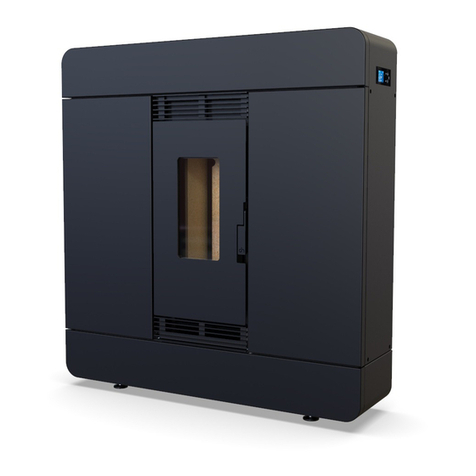
Defro Home
Defro Home AIRPELL 8 User manual

Defro Home
Defro Home QUADROOM User manual
Popular Stove manuals by other brands
Enviro
Enviro C-10804 owner's manual

Lopi
Lopi NorthField GSR2 Deluxe owner's manual
HASE
HASE COMO B.20 operating instructions

Breckwell
Breckwell Maverick SP22i Instruction and operation manual

CAPITAL STOVES
CAPITAL STOVES PANAMERA instructions
DutchWest
DutchWest 2478 Homeowner's installation and operating manual
