MRC EMF-831SD User manual

SD card real time datalogger, RS232/USB
RF EMF Strength Meter
Model : EMF-831SD
Your purchase of this
Personal RF EMF
Strength Meter
with SD CARD
DATALOGGER marks a
step forward for you
into the field of
precision measurement.
Although this METER is
a complex and delicate
instrument, its durable
structure will allow
many years of use if
proper operating
techniques are
developed. Please read
the following
instructions carefully
and always keep this
manual within easy
reach.
OPERATION MANUAL
3, Hagavish st. Israel 58817 Tel: 972 35595252, Fax: 972 3 5594529
MRC. 2.20

TABLE OF CONTENTS
1. FEATURES..................................................................................................................................
1
2. SPECIFICATIONS........................................................................
...................................................
2
3. FRONT PANEL DESCRIPTION..................................................................
...........................
5
4. MEASURING PROCEDURE....................................................................
...........................
6
4-1 RF EMF Strength Function selection and measurement
..............................................................
6
4-2 Data Hold..........................................................
...........................................................
7
4-3 Data Record ( Max., Min. reading )...............................................................................................................
7
5. DATALOGGER................................................................................
......................................................
8
5-1 Preparation before execute datalogger function...............................................................................
8
5-2 Auto Datalogger ( Set sampling time ≧ 1 second ).......................
...........................
9
5-3 Manual Datalogger ( Set sampling time = 0 second )....................
...........................
10
5-4 Check time and sampling time information..........................................................................................................
10
5-5 SD Card Data structure..................................................................................................
11
6. Saving data from the SD card to the computer..................................................................
12
7. ADVANCED SETTING...............................................................................
...........................
14
7-1 Set clock time ( Year/Month/Date, Hour/Minute/ Second )........................................
14
7-2 Set sampling time ................................................................................................................
15
7-3 Auto power OFF management ..........................................................
...........................
15
7-4 Set beeper Sound ON/OFF.................................................................
...........................
15
7-5 Decimal point of SD card setting................................................................................................
16
7-6
SD memory card format....................................................................................................
16
7-7 Set mesurement value gain .................................................
...........................
17
7-8 Set the alarm value .................................................................................
..........
17
7-9 Select the alarm function yes or no .................................................
...........................
17
8. POWER SUPPLY from DC ADAPTER.....................................................
...........................
18
9. BATTERY REPLACEMENT..............................................................................................
18
10. RS232 PC serial interface.................................................................................
...........................
18
11. PATENT.................................................................................................................................................
20

1. FEATURES
* Measurements range : 50MHz to 3.5GHz.
* For electromagnetic field strength measurement including mobile
phone base station antenna radiation, RF power measurement for
transmitters, wireless LAN (Wi-Fi) detection/installation, wireless
communication applications (CW, TDMA, GSM, DECT) and
microwave leakage
* The meter is a broadband device for monitoring high-frequency radiation
in the specific frequency ranges of 900MHz, 1800MHz, and 2.7GHz.
Other measurements can be made,using the entire range of 50MHz to 3.5GHz.
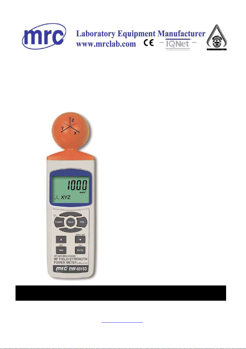
* Non-directional (isotropic) measurement with three-channel
(triaxial) measurement probe
* Microcomputer circuit provides intelligent function and high accuracy.
* Real time SD memory card Datalogger, it Built-in Clock
and Calendar, real time data recorder, sampling time set
from 1 second to 3600 seconds.
* Manual datalogger is available ( set the sampling
time to 0 second ), during execute the manual datalogger
function, it can set the different position ( location ) No.
( position 1 to position 99 ).
* Innovation and easy operation, computer is not need to
setup extra software, after execute datalogger, just take
away the SD card from the meter and plug in the SD card
into the computer, it can down load the all the measured
value with the time information ( year/month/date/
hour/minute/second ) to the Excel directly, then user can
make the further data or graphic analysis by themselves.
* SD card capacity : 1 GB to 16 GB.
* Can default auto power off or manual power off.
* Data hold, record max. and min. reading.
* Microcomputer circuit, high accuracy.
* Power by UM3/AA ( 1.5 V ) x 6 batteries or DC 9V adapter.
* RS232/USB PC COMPUTER interface.
* Heavy duty & compact housing case.
1

2. SPECIFICATIONS
2-1 General Specifications
Circuit Custom one-chip of microprocessor LSI
circuit.
Display LCD size : 52 mm x 30 mm
Measurement Digital, triaxial measurement.
method
Sensor type Electrical-field sensors
resolution 0.1mV/m, 0.1uA/m, 0.1uW/m^2, 0.001uW/cm^2
Range autorange
Datalogger Auto 2 to 3600 seconds
Sampling Time
Setting range @ Sampling time can set to 1 second,
but memory data may loss.
Manual Push the data logger button
once will save data one time.
@ Set the sampling time to
0 second.
@ Manual mode, can also select the
1 to 99 position ( Location ) no.
Data error no. ≦ 0.1 % no. of total saved data typically.
Memory Card SD memory card. 1 GB to 16 GB.
Advanced * Set clock time ( Year/Month/Date,
setting Hour/Minute/ Second )
* Set sampling time
* Auto power OFF management
* Set beep Sound ON/OFF
* Decimal point of SD card setting
* SD memory card Format
*Set temperature unit to ℃ or ℉
2

Over Indication Show " - - - - ".
Data Hold Freeze the display reading.
Memory Recall Maximum & Minimum value.
Sampling Time Approx. 1 second.
of Display
Data Output RS 232/USB PC computer interface.
* Connect the optional RS232 cable
UPCB-02 will get the RS232 plug.
* Connect the optional USB cable
USB-01 will get the USB plug.
Power off Auto shut off saves battery life or
manual off by push button.
Operating -20 ~ 50 ℃
Temperature
Operating Less than 85% R.H.
Humidity
Power Supply * Batteries( UM3, AA ) x 6 PCs, or equivalent.
* AC/DC power adapter .
(adapter is optional ).
Power Current Normal operation ( w/o SD card save data) :
Approx. DC 24 mA.
When SD card save the data :
Approx. DC 50 mA.
Weight 244 g/0.54 LB ( meter only ).
Dimension 177 x 68 x 45 mm
(7.0 x 2.7x 1.8 inch)
Accessories *
Instruction manual......................................
1 PCS
Included
Optional * SD Card ( 4 GB )
Accessories * USB cable, USB-01.
* RS232 cable, UPCB-02.
* Data Acquisition software,
* SW-U801-WIN., SW-E802.
AC to DC 9V adapter.
* Hard carrying case, CA-06.
* Soft carrying case, CA-05A.
3

2-2 Electrical Specifications (23±5
℃
, 25% ~ 75 % RH)
Frequency range: 50 MHz to 3.5GHz
Specified measurement range: 20 mV/m to 25.0 V/m
CW signal (f > 50MHz): 53 uA/m2 to 66.3mA/m
1 uW/m2 to 7.15W/m2
0 uW/cm2 to 0.715mW/cm2
Units mV/m, V/m, µA/m, mA/m, µW/m2,
mW/m2, W/m2, µW/cm2, mW/cm2
Display resolution: 0.1mV/m, 0.1uA/m, 0.1uW/m^2,
0.001uW/cm^2 , 0.001W/cm2
Dynamic range Typically 75dB
Absolute error 1.0dB
at 1 V/m & 2.45GHz
Frequency response 1.0dB (1.9GHz to 3.5GHz)
Sensor (with typical CAL factors) 2.4dB (50MHz to 1.9GHz)
Isotropy deviation Typically 1.0dB (f>2.45GHz)
Overload limit 0.42 mW/cm^2 per axis.
Thermal response (0 to 50°) ± 0.5dB
4

3. FRONT PANEL DESCRIPTION
Fig. 1
3-1 Display. 3-15 Battery compartment/Cover
3-2 Power Button 3-16 Tripod Fix Nut
3-3 Hold Button 3-17 RF EMF detect seneor
3-4 REC Button
3-5 ▲ Button ( UNIT Button)
3-6 ▼ Button ( X,Y,Z,XYZ Function Button )
3-7 Time Button (SET Button )
3-8 Enter Button ( Logger Button)
3-9 SD card socket
3-10 RS-232 output terminal
3-11 Reset Button
3-12 DC 9V adapter socket
3-13 Stand
3-14 Battery Cover Screws
5

4. MEASURING PROCEDURE
E-field sensors
The 3-channel sensor is located at the top of the meter. The three voltages
generated by the sensor are fed back to the meter.
The measurement of the field is done by moving the aerial of the sensor in
the desired measured environment. A direct wide band
measurement is obtained of the field that the measurement sensor is
subjected to. To find the value of the field emitted by a source of interference,
simply point the aerial towards it and get as close as possible (the value of the
field is inversely proportional to the distance of the sensor/emission source).
The operator must take care not to be between the source of disturbance and
the zone to be checked. The human body shields electromagnetic fields.
4-1 RF EMF Strength Function selection and measurement
1) Turn on the meter by pressing the " Power Button "
( 3-2, Fig. 1 ) > 1.5 seconds continuously.
*Pressing the " Power Button " ( 3-2, Fig. 1 )
continuously and > 1.5 seconds again will turn off the
meter.
2) measurement Function select
pressing and hold the " Function Button "( 3-6, Fig. 1 ),
to select X axis,Y axis, Z axis, and XYZ axis measurement Function.
3) measurement UNIT select
pressing and hold the " UNIT Button "( 3-5, Fig. 1 ),
to select …
1mV/m, When Test values > 999.9 ,the unit auto chang to V/m unit ,
2µA/m, When Test values > 999.9 ,the unit auto chang to mA/m unit ,
3µW/m^2, When Test values > 999.9 ,the unit auto chang to mW/m^2 unit ,
mW/m^2, When Test values > 999.9 ,the unit auto chang to W/m^2 unit ,
4
µW/cm^2, When Test values > 999.9 ,the unit auto chang to mW/cm^2 unit ,
4) measurement Procedure
1. Hold the meter at arm’s length.
2. Make several measurements at various locations around the work place
or the interested areas as described above. This is particularly important
if the field conditions are unknown.
6

3. Pay special attention to measuring the neighboring vicinity for possible
radiation sources. Apart from active sources, those components connected
to a source may also act as radiators. For example, the cables used in
diathermy equipment may also radiate electromagnetic energy. Note
that metallic objects within the field may locally concentrate or amplify the
field from a distant source.
4-2 Data Hold
During the measurement, press the " Hold Button " ( 3-3,
Fig. 1 ) once will hold the measured value & the " HOLD " symbole
will be light, Press the " Hold Button " once again will release the data
hold function , ( 3-20, Fig. 1) HOLD symbole will be quenched
4-3 Data Record ( Max., Min. reading )
1) The data record function records the maximum and minimum readings.
Press the " REC Button " ( 3-4, Fig.1 ) once to start the Data Record
function and there will be a " REC " symbol indicator "
will be light.
2) With the " REC " Symbol is light on the display :
a) Press the " REC Button " ( 3-4, Fig. 1 ) once, the "
REC and MAX Symbol indicator will be light ,
and the maximum value will appear on the display.
b) Press the " REC Button " ( 3-4, Fig. 1 ) again, the
" REC and MIN " Symbol indicator will be light ,
and the minimum value will appear on the display.
c) To exit the memory record function, just press the
" REC " button for 1.5 seconds at least. The display will
revert to the current reading, red led indicator will be quenched
7

5. DATALOGGER
5-1 Preparation before execute datalogger function
a. Insert the SD card
Prepare a " SD memory card " ( 1 G to 16 G, optional ),
insert the SD card into the " SD card socket " ( 3-9, Fig. 1).
The front panel of the SD card should face against the
the down case.
*It recommend use memory card
≦
4 GB.
b. SD card Format
If SD card just the first time use into the meter, it
recommend to make the " SD card Format " at first. ,
please refer chapter 7-6, (page 16 ) .
*
It recommend strongly, do not use memory cards that
have been formatted by other meter or by other installation
(such as camera…) .
Reformat the memory card with your meter.
*
If the SD memory card exist the trouble during
format by the meter use the computer to
reformat again can fix the problem .
c. Time setting
If the meter is used at first time, it should to adjust the
clock time exactly, please refer chapter 7-1 ( page 14 ).
d. Decimal for the numerical data structure of SD card is
default used the " . " as the decimal, for
example "20.6" "1000.53" . But in certain
countries ( Europe ...) is used the " , " as the
decimal point, for example " 20, 6 "
"1000,53". Under such situation, it should
change the Decimal character at first, details
of setting the Decimal point, refer to Chapter
7-5, page 16.
8

5-2 Auto Datalogger ( Set sampling time
≧
1 second )
a. Start the datalogger
Press the " LOG Button ( 3-8, Fig. 1 ) > 1.5 seconds
continuously, the LCD will show the text of " LOGGER "
indecator and flashing per second, at the same
time the measuring data along the time information will
be saved into the memory circuit.
Remark :
*How to set the sampling time, refer to Chapter 7-2,
page 15 .
*How to set the beeper sound is enable, refer to
Chapter 7-4, page 15 .
b. Pause the datalogger
During execute the Datalogger function, if press the
" LOG Button " ( 3-8, Fig. 1 ) once will pause the
Datalogger function ( stop to save the measuring data
into the memory circuit temporally ). In the same time
the " LOGGER " symbol will stop flashing.
Remark :
If press the " LOG Button " ( 3-8, Fig. 1 ) once again
will execute the Datalogger again, the " LOGGER "
symbol will flashing.
c. Finish the Datalogger
During execute the Datalogger function, press the
" LOG Button ( 3-8, Fig. 1 ) > 1.5 seconds continuously
again will finish the Datalooger function, the " LOGGER "
text will be disappeared and finish the Datalogger function.
9

5-3 Manual Datalogger ( Set sampling time = 0
second )
a. Set sampling time is to 0 second
Press the " LOG Button ( 3-8, Fig. 1 )>1.5 second, the LCD
will show the indecator " LOGGER " and " Position no. " symbol
then press the " LOG Button " ( 3-8, Fig. 1 ) once , the
" LOGGER " symbol will flashing once and Beeper will sound once
at the same time the measuring data along the time
information will be saved into the memory circuit .
Remark :
During execute the Manual Datalogger, it can use the "
▲
Button " ( 3-5, Fig. 1) or "
▼
Button " ( 3-6, Fig. 1 ) to
set the measuring position ( 1 to 99, for example room 1
to room 99 ) to identify the measurement location , the
Top Display will show P x ( x = 1 to 99 ).
b. Finish the Datalogger
During execute the Datalogger function, press the " LOG
Button ( 3-8, Fig. 1 ) > 1.5 seconds continuously again will
finish the Datalooger function, the Position no. " PXX " will
be disappeared and finish the Datalogger function.
5-4 Check time information
During the normal measurement ( not execute the
Datalogger ), If press " Time " ( 3-7, Fig. 1 )
once , the LCD display will present the time
information of Year/Month/Date ,Hour/ Minute/Second
and the Sampling time information in sequence.
Data column reach to 30,000 columns, then
will generate a new file, for example EMF01002.XLS
3)
Under the folder EMF01\, if the total files more
than 99 files, will generate anew route, such as
EMF02\ ........
10

5-5 SD Card Data structure
1) When the SD card is used into the meter, the SD card
When the first time, the SD card is used into the meter,
the SD card will generate a folder :
EMF01
2)
If the first time to execute the Datalogger,
under the route EMF01\, will generate a new
file name EMF01001.XLS.
After exist the Datalogger, then execute again,
the data will save to the EMF01001.XLS until
Data column reach to 30,000 columns, then
will generate a new file, for example EMF01002.XLS
3)
Under the folder EMF01\, if the total files more
than 99 files, will generate anew route, such as
EMF02\ ........
4)
The file's route structure :
EMF01\
EMF01001.XLS
EMF01002.XLS
.....................
EMF01099.XLS
EMF02\
EMF02001.XLS
EMF02002.XLS
.....................
EMF02099.XLS
EMFXX\
.....................
Remark : XX - Max. value is 10.
11

6. Saving data from the SD card
to the computer ( EXCEL software )
1) After execute the Data Logger function, take away the
SD card out from the " SD card socket " ( 3-9, Fig. 1 ).
2) Plug in the SD card into the Computer's SD card slot
( if your computer build in this installation ) or
insert the SD card into the " SD card adapter ". then
connect the " SD card adapter " into the computer.
3) Power ON the computer and run the " EXCEL software ".
Down load the saving data file ( for example the file
name : TME01001.XLS, TME01002.XLS ) from the SD
card to the computer. The saving data will present into
the EXCEL software screen ( for example as following
EXCEL data screens ) , then user can use those EXCEL
data to make the further Data or Graphic analysis
usefully.
EXCEL data screen (for example )
12

EXCEL graphic screen (for example )
13

7. ADVANCED SETTING
Under do not execute the Datalogger function,
press the " SET Button " ( 3-7, Fig. 1 ) continuously at
least 1.5 seconds will enter the " Advanced Setting " mode.
then press the " SET Button " ( 3-7, Fig. 1 ) once a while display will show :
SET DATE..........
Set clock time ( Year/Month/Date, Hour/Minute/Second )
SP-T........... Set sampling time ( Seconds )
POFF........ Auto power OFF management
BEEP........ Set beeper sound ON/OFF
DEC........... Set SD card Decimal character
SD-F............ SD memory card Format
CAL............ Set alarm mesurement value gain .
ALARM VALUE........
Set alarm value .
ALARM YES / NO…
Set alarm to yes or no.
Remark :
During execute the " Advanced Setting " function,if press
" Power Button " ( 3-2, Fig. 1 ) once will exit the " Advanced Setting "
function, the LCD will return to normal screen.
7-1 Set clock time ( Year/Month/Date,Hour/Minute/ Second )
When the lcd display show " dAtE "
1) Press the " Enter Button " ( 3-8, Fig. 1 ) once, ,YY symbol will
light ,Use the " ▲ Button " ( 3-5, Fig. 1 ) or " ▼ Button "
( 3-6, Fig. 1 ) to adjust the correct value ( Setting start from
Year value ). press the " Enter Button " ( 3-8, Fig. 1 ) once,
After the desired value is set, YY symbol will be quenched
and will going to Month adjustment ( for example, first setting
value is Year then next to adjust Month, Date, Hour,
Minute, Second value ).
2) After set all the time value ( Year, Month, Date, Hour,
Minute, Second ), the screen will
jump to " Set sampling time " setting screen (Chapter 7-2 ).
14

Remark :
After the time value is setting, the internal clock will
run precisely even Power off if the battery is under
normal condition ( No low battery power ).
7-2 Set sampling time ( Seconds )
When the lcd display show " SP-t " ,DD/s led indicator will light
1) Use the " ▲ Button " ( 3-5, Fig. 1 ) or " ▼ Button " (
3-6, Fig. 1 ) to adjust the value ( 2 to 3600 seconds ).
2) After the Sampling value is selected, press the "
Enter Button " ( 3-8, Fig. 1 ) will save the setting
function with default.
7-3 Auto power OFF management
When the lcd display show " PoFF "
1) Use the " ▲ Button " ( 3-5, Fig. 1 ) or " ▼ Button "
( 3-6, Fig. 1 ) to select the led display show " YES " or
" no ".
YES - Auto Power Off management will enable.
no - Auto Power Off management will disable.
2) After select the lcd displary show " YES " or " no ", press the
" Enter Button " ( 3-8, Fig. 1 ) will save the setting
function with default.
7-4 Set beeper sound ON/OFF
When the lcd display show " bEEP "
1) Use the " ▲ Button " ( 3-5, Fig. 1 ) or " ▼ Button "
( 3-6, Fig. 1 ) to select the lcd display show " YES " or
" no ".
15

YES - Meter's beep sound will be ON with default.
no - Meter's beep sound will be OFF with default.
2) After select the led displary show " YES " or " no ", press the
" Enter Button " ( 3-8, Fig. 1 ) will save the setting
function with default.
7-5 Decimal point of SD card setting
The numerical data structure of SD card is default used
the " . " as the decimal, for example "20.6" "1000.53" .
But in certain countries ( Europe ...) is used the " , " as
the decimal point, for example " 20,6 " "1000,53".
Under such situation, it should change the Decimal
character at first.
When the lcd display show " dEC "
1) Use the " ▲ Button " ( 3-5, Fig. 1 ) or " ▼ Button "
( 3-6, Fig. 1 ) to select the lcd display show " USA " or
" Euro ".
USA - Use " . " as the Decimal point with default.
Euro - Use " , " as the Decimal point with default.
2) After select the display show " USA " or " Euro ",
press the " Enter Button " ( 3-8, Fig. 1 ) will save the
setting function with default.
7-6 SD memory card Format
When the lcd display show " SdF "
1) Use the " ▲ Button " ( 3-5, Fig. 1 ) or " ▼ Button " (
3-6, Fig. 1 ) to select the lcd display to show " YES " or
" no ".
YES - Intend to format the SD memory card
no - Not execute the SD memory card format
16

2) If select the lcd display show " YES ", press the " Enter Button
" ( 3-8, Fig. 1 ) once , the Display will show text
" Enter " and " YES " to Flashing interaction , if make sure to do the
SD memory card format , then press " Enter Button "
once will format the SD memory ( display will show "SD CARD & For-" )
and clear all the existing data that already saving into the SD card.
* if no sd memory card , the Display will show text " SD CARD " and
" EMPTY " then jump to next setting .
7-7 Set mesurement value gain.
When the lcd display show " CAL "
1) Use the " ▲ Button " ( 3-5, Fig. 1 ) or " ▼ Button "( 3-6, Fig. 1 )
to set mesurement value gain.
2) After Display will show gain value, press the " Enter Button "
( 3-8, Fig. 1 ) will save the setting value with default.
7-8 Set the alarm unit and value .
When the lcd display show " ALARM value "
1) Use the " ▲ Button " ( 3-5, Fig. 1 ) or " ▼ Button "( 3-6, Fig. 1 )
to set alarm unit ,then press the " Enter Button " .
2) After Display will show alarm value,use the " ▲ Button " or " ▼ Button "
set alarm value, then press the " Enter Button " ( 3-8, Fig. 1 ) will save
the alarm value with default.
7-9 Select the alarm function yes or no.
When the led display show " ALARM YES/NO "
1) Use the " ▲ Button " ( 3-5, Fig. 1 ) or " ▼ Button " (
3-6, Fig. 1 ) to select the alarm function to show " YES " or
"No ".
YES - the alarm function to enable.
NO - the alarm function to disable.
17

8. POWER SUPPLY from DC
ADAPTER
The meter also can supply the power supply from the
DC 9V Power Adapter ( optional ). Insert the plug of
Power Adapter into " DC 9V Power Adapter Input Socket "
( 3-12, Fig. 1 ).
9. BATTERY REPLACEMENT
1) When the left corner of " Lobattery text " indicator
is light, it is necessary to replace the battery. However, in-spec.
measurement may still be made for several hours after
low battery indicator appears before the instrument
become inaccurate.
2) Loose the " Battery Cover Screws " ( 3-14, Fig. 1 )
and take away the " Battery Cover " ( 3-15, Fig. 1 )
from the instrument and remove the battery.
3) Replace with DC 1.5 V battery ( UM3, AA,
Alkaline/heavy duty ) x 6 PCs, and reinstate the cover.
4) Make sure the battery cover is secured after changing
the battery.
10. RS232 PC SERIAL INTERFACE
The instrument has RS232 PC serial interface via a 3.5
mm terminal ( 3-10, Fig. 1 ).
The data output is a 16 digit stream which can be
utilized for user's specific application.
A RS232 lead with the following connection will be
required to link the instrument with the PC serial port.
18
Other MRC Measuring Instrument manuals
Popular Measuring Instrument manuals by other brands

ANDERSON-NEGELE
ANDERSON-NEGELE FMQ operating manual

PCB Piezotronics
PCB Piezotronics J356A43 Installation and operating manual

SatLab
SatLab Freyja GNSS RTK user manual

MindWare Technologies
MindWare Technologies MindWare Mobile product manual

Akai
Akai GX-280 Operator's manual

Viavi
Viavi SmartPocket OLP-35SC operating manual

ZBM
ZBM MINI OTDR user manual

Dostmann Electronic
Dostmann Electronic P705 Operation manuals

Kaiterra
Kaiterra Sensedge Mini installation guide

Bosch
Bosch DLE 40 Professional Original instructions

FLIR
FLIR Imaging Moisture Meter Plus IGM MR176 Getting started

Hanna Instruments
Hanna Instruments HI 93749 instruction manual