E2S BExH120DDC024 User manual

INSTRUCTION MANUAL
BExH120D & BExH120D-R
Alarm Horn Sounder
ATEx/IECEx & UKEx Gas & Dust
European Safety Systems Ltd. Impress House, Mansell Road, Acton, London W3 7QH www.e2s.com Tel: +44 (0)208 743 8880
Document No. D190-00-031-IS Issue 5 12-09-2022 Sheet 1 of 6
BExH120D BExH120D-R
1. Product Table
Unit Type Code Nominal
Input Voltage
Nominal
Input Current Max I/P Voltage
Sound
Pressure Level
dB(A)
Max* Nom
.†
BExH120DDC024 24Vdc 400mA 30V
Flare:
123dB(A)
Radial:
115dB(A)
Flare:
117dB(A)
Radial:
110dB(A)
BExH120DAC115 115Vac 130mA 126.5V
BExH120DAC230 230Vac 65mA 253V
*Max = Tone 4
†
Nom. = Tone 44
The table shows the input current taken by the various sounders.
The current levels shown above are for the 440Hz Continuous tone @ nominal input voltage.
Nominal current at nominal voltage.
Table 1: Electrical Ratings.
It is important that a suitable power supply is used to run the equipment. The power supply selected must have the necessary capacity
to provide the input current to all of the units.
The above table shows the input current taken by the various sounders and shows the maximum voltage at which the sounders can
be operated:
The input current will vary according to the voltage input level and the frequency of the tone selected.
2. Warnings
DO NOT OPEN WHEN AN EXPLOSIVE ATMOSPHERE IS PRESENT
DO NOT OPEN WHEN ENERGIZED
POTENTIAL ELECTROSTATIC CHARGING HAZARD – CLEAN ONLY WITH A DAMP CLOTH
COVER BOLTS CLASS A4-80
USE HEAT RESISTING CABLES AND CABLE GLANDS (RATED 110°C) AT AMB. TEMPERATURES OVER
40°C

European Safety Systems Ltd. Impress House, Mansell Road, Acton, London W3 7QH www.e2s.com Tel: +44 (0)208 743 8880
Document No. D210-00-031-IS Issue 5 12-09-2022 Sheet 2 of 6
3. Marking & Rating Information
The BExH120D Alarm Horns comply with the following standards for
hazardous locations:
3.1 ATEX / IECEx & UKEx Ratings
Standards
EN60079-0:2018/IEC60079-0:2017 (ed.7): Explosive
Atmospheres - Equipment General Requirements.
EN60079-1:2014/IEC60079-1:2014 (ed.7): Explosive
Atmospheres - Equipment Protection by Flameproof Enclosures
“d”.
EN60079-31:2014/IEC60079-31:2013 (ed.2): Explosive
Atmospheres - Equipment Dust Ignition Protection by enclosure
“t”.
Model No: Rating
BExH120D Ex db IIC T4 Gb Ta. -50°C to +55°C
Ex db IIB T4 Gb Ta. -50°C to +70°C
Ex tb IIIC T100°C Db Ta. -50°C to +55°C
Ex tb IIIC T115°C Db Ta. -50°C to +70°C
See Product table for electrical ratings of each unit model
Certificate No. KEMA 99ATEX6312X
IECEx KEM 10.0003X
UL22UKEX2638X
Epsilon x
Equipment Group
and Category:
II 2G
II 2D
CE Marking and
Notified Body No. 2813
UKCA Marking and
Approval Body No.
0518
4. Zones, Gas Group, Category and
Temperature Classification
The units can be installed in locations with the following conditions:
A
rea Classification Gas
Zone 1 Explosive gas air mixture likely to occur in normal
operation.
Zone 2
Explosive gas air mixture not likely to occur in
normal operation, and if it does, it will only exist for
a short time.
Gas Groupings
Group IIA Propane
Group IIB Ethylene
Group IIC Hydrogen and Acetylene (up to 55°C ambient)
Temperature Classification for Gas Applications
T1 450
o
C
T2 300
o
C
T3 200
o
C
T4 135
o
C
A
rea Classification Dust
Zone 21 Explosive dust air mixture likely to occur in normal
operation.
Zone 22
Explosive dust air mixture not likely to occur in
normal operation, and if it does, it will only exist for
a short time.
Dust Groupings
Group IIIA Combustible Dusts
Group IIIB Non-Conductive Dusts
Group IIIC Conductive Dusts
E
q
ui
p
ment Cate
g
or
y
2G, 2D
E
q
ui
p
ment Protection Level
Gb, Db,
Maximum Surface Tem
p
erature for Dust A
pp
lications
100°C at +55°C
115°C at +70°C
A
mbient Temperature Range
-50°C to +55°C Gas Groups IIA, IIB and IIC
-50°C to +70°C Gas Groups IIA and IIB
-50°C to +70°C Dust Grou
p
s IIIA, IIIB and IIIC
IP Rating
IP66/67 to EN/IEC60529 and
IP6X to EN/IEC60079-0, EN/IEC60079-31
The sounder must only be installed by suitably qualified personnel in
accordance with the latest issues of the relevant standards:
EN60079-14 / IEC60079-14: Explosive atmospheres - Electrical
installations design, selection and erection
EN60079-10-1 / IEC60079-10-1: Explosive atmospheres -
Classification of areas. Explosive gas atmospheres
EN60079-10-2 / IEC60079-10-2: Explosive atmospheres -
Classification of areas. Explosive dust atmospheres
The installation of the sounder must also be in accordance with any
local codes that may apply and should only be carried out by a
competent electrical engineer who has the necessary training.

European Safety Systems Ltd. Impress House, Mansell Road, Acton, London W3 7QH www.e2s.com Tel: +44 (0)208 743 8880
Document No. D210-00-031-IS Issue 5 12-09-2022 Sheet 3 of 6
145.0
212.0
30.030.0
145.0
92.4
30.030.0
96,3
5. Special Conditions for Safe Use
Repair of the flamepath / flameproof joints is not permitted.
The enclosure is non-conducting and may generate an
ignition-capable level of electrostatic charges under certain
extreme conditions (such as high-pressure steam). The user
should ensure that the equipment is not installed in a location
where it may be subjected to external conditions that might
cause a build-up of electrostatic charges on non-conducting
surfaces.
Additionally, cleaning of the equipment should be done only
with a damp cloth.
6. Product Mounting and Access
The location of the sounder should be made with due regard
to the area over which the warning signal must be visible. They
should only be fixed to services that can carry the weight of the
unit.
The BEx sounder should be secured to any flat surface using
at least two of the three 7mm fixing holes on the stainless steel
U shaped mounting bracket. See Figure 1. The required angle
can be achieved by loosening the two large bracket screws in
the side of the unit, which allow adjustment of the sounder in
steps of 18°. On completion of the installation then two large
bracket adjustment screws on the side of the unit must be fully
tightened to ensure that the unit cannot move in service.
Fig. 1a Fixing Location for Sounder Flare
Fig. 1b Fixing Location for Sounder Radial
7. Access to the Flameproof Enclosure
To access the Ex d chamber, remove the four M6 hexagon
socket head screws and withdraw the flameproof cover taking
extreme care not to damage the flameproof joints in the
process. M6 cover screws are Class A4-80 stainless steel and
only screws of this category can be used for the enclosure.
Fig. 2 Accessing the Explosion proof Enclosure.
On completion of the installation, the flameproof joints should
be inspected to ensure that they are clean and that they have
not been damaged during installation.
Check that the earth bonding wire between the two castings is
secure and the ‘O’ ring seal is in place. When replacing the
flameproof cover casting ensure that it is square with the
flameproof chamber casting before inserting. Carefully push
the cover in place allowing time for the air to be expelled. Only
after the cover is fully in place should the four M6 Stainless
Steel A4-80 cover bolts and their spring washer be inserted
and tightened down. If the cover jams while it is being inserted,
carefully remove it and try again. Never use the cover bolts to
force the cover into position.
Warning – High voltage may be present,
risk of electric shock. DO NOT open when
energised, disconnect power before
opening.
Warning – Hot surfaces. External surfaces
and internal components may be hot after
operation, take care when handling the
equipment.
(Appropriate cable glands
to be customer su
pp
lied
)
Flameproof cover
M6 Cover
Screws
M6 Spring
Washer

European Safety Systems Ltd. Impress House, Mansell Road, Acton, London W3 7QH www.e2s.com Tel: +44 (0)208 743 8880
Document No. D210-00-031-IS Issue 5 12-09-2022 Sheet 4 of 6
8. Selection of Cable. Cable Glands, Blanking
Elements & Adapters
When selecting the cable size, consideration must be given to
the input current that each unit draws (see table above), the
number of sounders on the line and the length of the cable
runs. The cable size selected must have the necessary
capacity to provide the input current to all of the sounders
connected to the line.
For ambient temperatures over +40ºC the cable entry
temperature may exceed +70ºC and therefore suitable heat
resisting cables and cable glands must be used, with a rated
service temperature of at least 110ºC
The dual cable gland entries have an M20 x 1.5 entry thread.
To maintain the ingress protection rating and mode of
protection, the cable entries must be fitted with suitably rated
ATEX / IECEx or UKEx certified cable glands and/or suitably
rated ATEX / IECEx or UKEx certified blanking devices during
installation according to EN / IEC60079-14.
If a high IP (Ingress Protection) rating is required then a
suitable sealing washer must be fitted under the cable glands
or blanking plugs.
For use in explosive dust atmospheres, a minimum ingress
protection rating of IP6X must be maintained.
The BEx sounder range can be supplied with the following
types of adapters:
M20 to ½” NPT
M20 to ¾” NPT
M20 to M25
It is important to note that stopping plugs cannot be fitted onto
adapters, only directly onto the M20 entries.
Any other adapters used must be suitably rated and ATEX /
IECEx certified adapters.
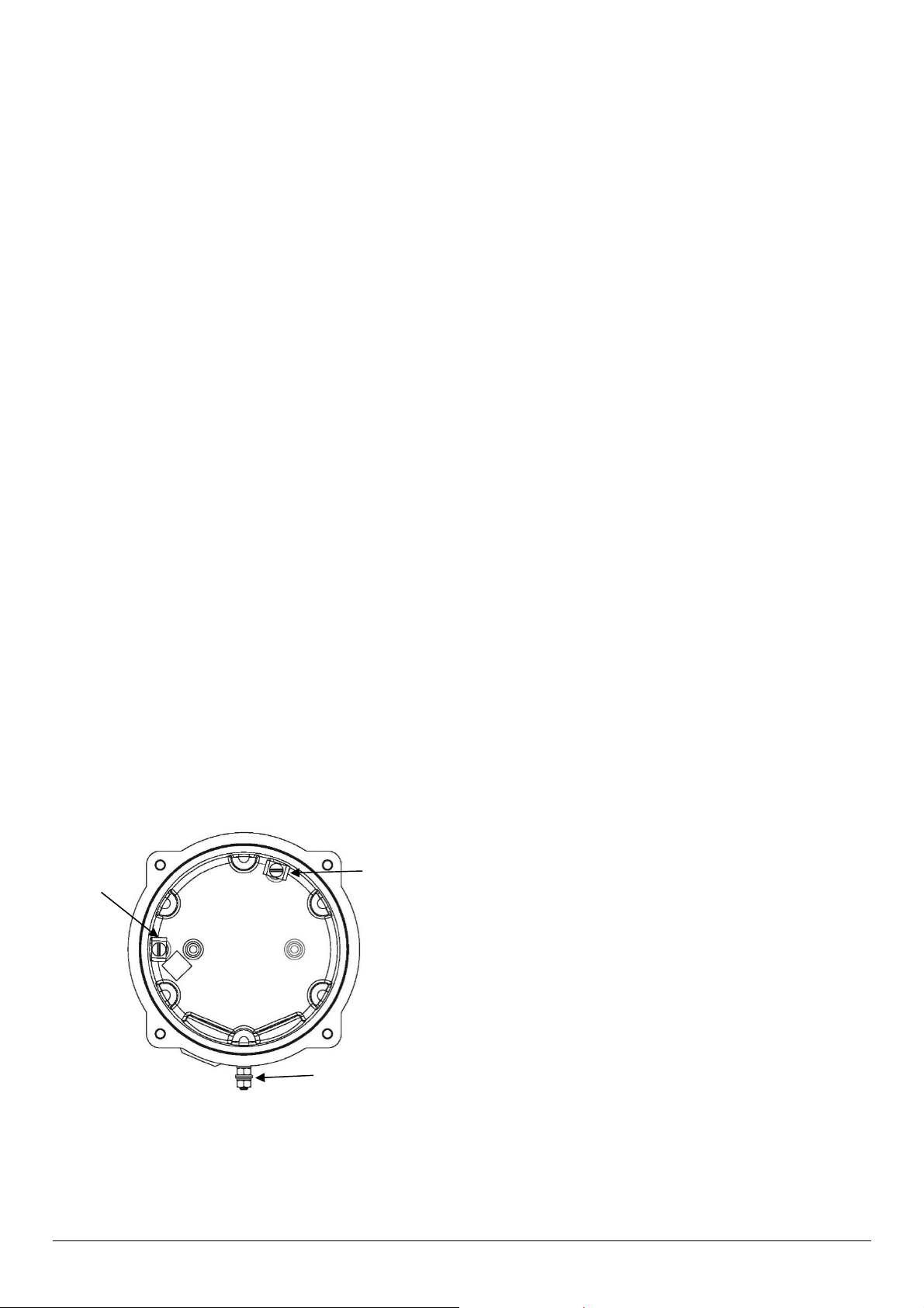
9. Earthing
Both AC and DC sounder units must be connected to an earth.
The units are provided with internal and external earth
terminals which are both located on the terminal chamber
section of the unit.
Fig. 3 Internal View of Cover
When using the internal earth terminal ensure that the
stainless steel M4 flat washer is between the incoming earth
wire and the enclosure.
Internal earthing connections should be made to the Internal
Earth terminal in the base of the housing using a ring crimp
terminal to secure the earth conductor under the earth clamp.
The earth conductor should be at least equal in size and rating
to the incoming power conductors. Tighten M4 Earth screw to
1Nm.
External earthing connections should be made to the M5 earth
stud, using a ring crimp terminal to secure the earth conductor
to the earth stud. The external earth conductor should be at
least 4mm² in size. Tighten the Earth nut to 3Nm. Please firmly
tighten the external grounding terminal so that the stud does
not become loose and lay the ground wire so that it is not
caught by twisting and sagging.
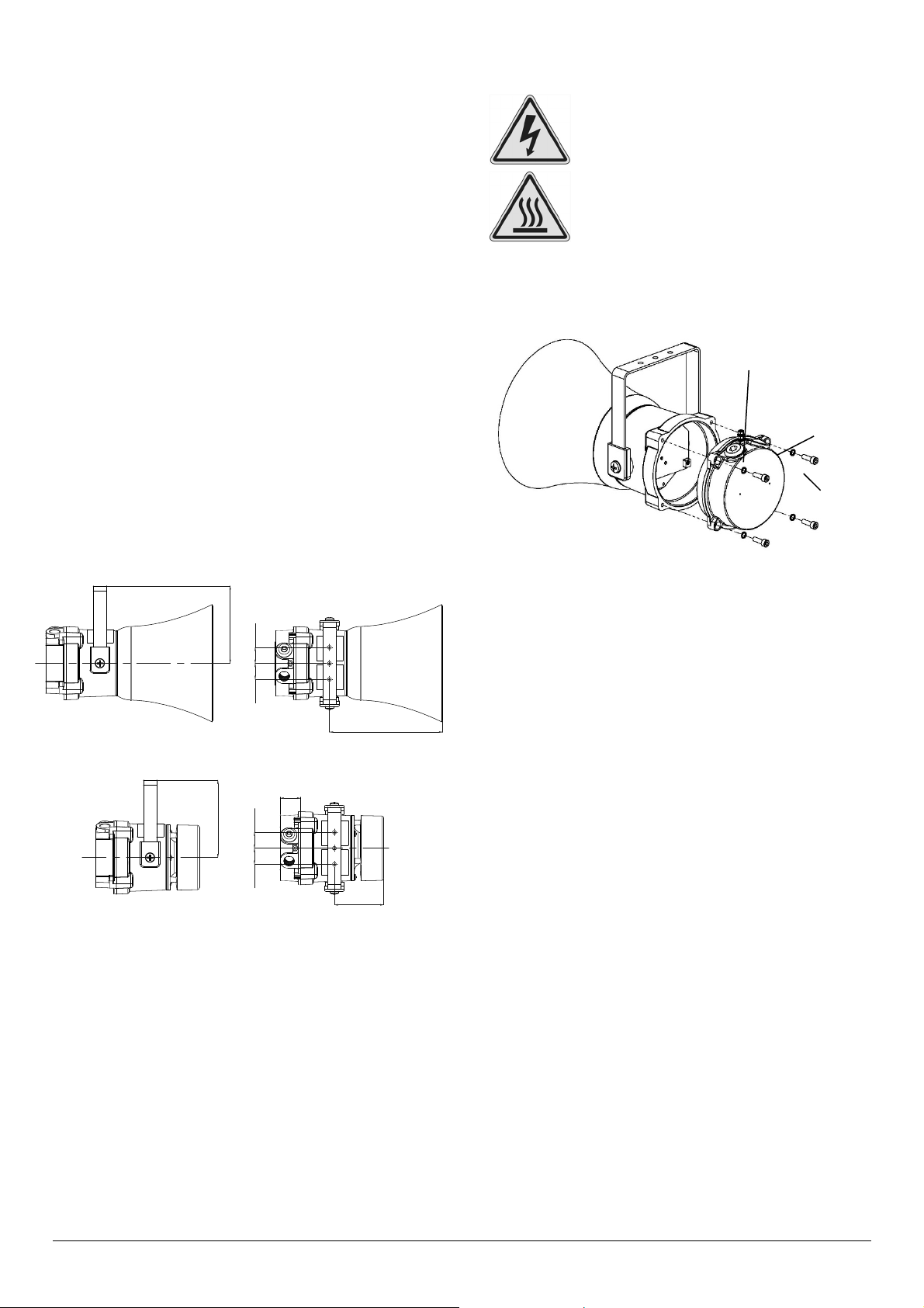
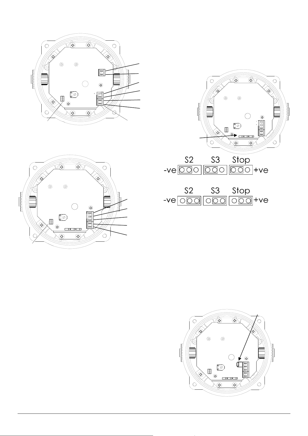
10. Cable Connections
Electrical connections are to be made into the terminal blocks
on the PCBA located in the flameproof enclosure. See section
7 of this manual for access to the flameproof enclosure.
Wires having a cross sectional area between 0.5 mm² to
2.5mm² can be connected to each terminal way. If an input and
output wire is required the 2-off Live/Neutral or +/- terminals
can be used. If fitting 2-off wires to one terminal way the sum
of the 2-off wires must be a maximum cross sectional area of
2.5mm². Strip wires to 8mm. Wires may also be fitted using
ferrules. Terminal screws need to be tightened down with a
tightening torque of 0.45 Nm / 5 Lb-in. When connecting wires
to the terminals great care should be taken to dress the wires
so that when the cover is inserted into the chamber the wires
do not exert excess pressure on the terminal blocks. This is
particularly important when using cables with large cross
sectional areas such as 2.5mm².
External Earthing
Internal
Earthing
Internal
Bonding
Wire
Terminal
2-off M20
Cable
Entries

European Safety Systems Ltd. Impress House, Mansell Road, Acton, London W3 7QH www.e2s.com Tel: +44 (0)208 743 8880
Document No. D210-00-031-IS Issue 5 12-09-2022 Sheet 5 of 6
11. AC Wiring
N L - 2 3 S
top
123
Fig. 4 AC Terminals
12. DC Wiring
+ - 2 3 Stop
123
S2 S3 Stop
+ve
-ve
Fig. 6 DC Terminals
12.1 Stop Terminal
The user can remotely activate and deactivate the BExH120D
Hootronic DC sounder by switching a connection from the
“Stop” terminal to the –ve or +ve supply lines, depending on
which switching mode is being used +ve or –ve (see above)
whilst the unit is powered. To achieve the “tail off” sound at
switch off the unit must remain powered.
12.2 Stage Switching Polarity (DC Units Only)
The BExH120D DC sounders have the facility to use either +ve
or –ve switching to change the tone to the second and third
stages. Negative switching is the default setting. For –ve
switching connect the two headers on the pcb to the left-hand
(marked –ve) and centre pins. For +ve switching connect the
headers to the right hand (marked +ve) and the centre pins.
(Refer to Fig. 7)
+ - 2 3 S
top
123
S2 S3 Stop
+ve
-ve
Stage Headers Set for –ve Switching
Stage Headers Set for +ve Switching
Fig. 7 Stage Switching Polarity
12.3 Line Monitoring
On BExH120D DC units, dc reverse line monitoring can be
used if required. All DC sounders have a blocking diode fitted
in their supply input lines. An end of line monitoring diode or
an end of line monitoring resistor can be connected across the
+ve and –ve terminals. If an end of line resistor is used it must
have a minimum resistance value of 3k3Ω and a minimum
power rating of 0.5 watts or a minimum resistance value of
500Ω and a minimum power rating of 2 watts.
The resistor must be connected directly across the +ve and -
ve terminals as shown in the following drawing. The resistor
leads should be kept as short as possible.
+ - 2 3 S
top
123
S2 S3 Stop
+ve
-ve
Fig. 8 End of Line Resistor Placement
End of Line Resisto
r
Stage Headers
AC
Terminals
N
L
C/-
S2
S3
Stop
C/-
Sound Headers
+
C/-
S2
S3
Stop
C/-
Stage
Headers
C/-

European Safety Systems Ltd. Impress House, Mansell Road, Acton, London W3 7QH www.e2s.com Tel: +44 (0)208 743 8880
Document No. D210-00-031-IS Issue 5 12-09-2022 Sheet 6 of 6
13. Settings
The BExH120D Hootronic sounder has 5 different traditional
sounds that can be selected for the first stage alarm. The
sounders can then be switched to sound second and third
stage alarm sounds. The sounds are selected by pin headers
on the pcb for both DC and AC units. The sound table below
shows the pin header positions for the 5 sounds and which
sounds are available for the second and third stages.
The BExH120D Hootronic sounder has the facility to replicate
the “tail off” traditionally associated with these sounds when
generated by electro-mechanical devices. The switching is
achieved using the “Stop” terminal (see section 12 & 13).
See figure 5 for header location on AC units and Figure 7 for
header location on DC units.
Sound Selection Table
Stage 1 Description Stage 2 Stage 3 Header
Sound 1 Industrial Hooter Sound 3 Sound 5
Sound 2 High Frequency
Mechanical Siren Sound 1 Sound 5
Sound 3
Medium
Frequency
Mechanical Siren
Sound 1 Sound 5
Sound 4
Electro
Mechanical
Buzzer
Sound 2 Sound 5
Sound 5 Mechanical Bell Sound 1 Sound 2
13.1 Volume Control
The output level of the BEx sounder can be set by adjusting
the volume control potentiometer (see Fig 9). For maximum
output, set the potentiometer fully clockwise.
N L - 2 3 S
top
123
BExH120D AC
+ - 2 3 S
top
123
S2 S3 Stop
+ve
-ve
BExH120D DC
Fig.10 Location of Volume Control Potentiometer
14. Maintenance, Overhaul & Repair
Maintenance, repair and overhaul of the equipment should
only be carried out by suitably qualified personnel in
accordance with the current relevant standards:
EN60079-19
IEC60079-19
Explosive atmospheres - Equipment
repair, overhaul and reclamation
EN 60079-17
IEC60079-17
Explosive atmospheres - Electrical
installations inspection and maintenance
The acoustic horn is made out of ABS plastic, therefore to
avoid a possible ELECTROSTACTIC CHARGE the unit must
only be cleaned with a damp cloth.
Units must not be opened while an explosive atmosphere is
present.
If opening the unit during maintenance operations a clean
environment must be maintained and any dust layer removed
prior to opening the unit.
Warning - High noise levels above 85dB(A)
during operation. High levels of noise may
cause hearing loss, wear suitable ear
p
rotection when e
q
ui
p
ment is in o
p
eration.
Volume Control
Potentiometer
Volume Control
Potentiometer

warning signals
2S
BEx
EUROPEAN SAFETY SYSTEMS LTD
IMPRESS HOUSE
MANSELL ROAD
ACTON
LONDON W3 7QH
WWW.E2S.COM
C
THIS DRAWING AND ANY INFORMATION OR DESCRIPTIVE
MATTER THEREIN IS COMMUNICATED IN CONFIDENCE AND
IS THE COPYRIGHT PROPERTY OF EUROPEAN SAFETY
SYSTEMS LTD. NEITHER THE WHOLE OR ANY EXTRACT MAY
BE DISCLOSED, LOANED, COPIED OR USED FOR
MANUFACTURING OR TENDERING PURPOSES WITHOUT THEIR
WRITTEN CONSENT.
EUROPEAN SAFETY SYSTEMS LTD.
AS PER LATEST DATE OF ISSUE SHOWN ABOVE
DRAWING TO BS8888:2000
GEOMETRIC TOLERANCES TO ISO1101:1983
LINEAR DIMENSIONAL TOLS
ANGULAR DIMENSIONAL TOLS
STANDARDS
MOD No. REASON - INITIAL - DATEISSUE
DATE
APPROVED
CHECKED DATE
DATE
DRAWN WEIGHT (Kg)
SURFACE FINISH
MATERIAL
ALTERNATIVE MATERIAL SHEETSCALE
TITLE
A3
IF IN DOUBT, ASK -
DO NOT SCALE
ALL DIMENSIONS IN MM
DRAWING NUMBER
A
B
C
D
E
F
G
109
G
F
E
78
6
5
D
C
134
2
A
B
D210-06-031
R.S.RAIT
B.ISARD
R.N.POTTS OF
NTS 1 1
OPTIONAL LINE MONITORING RESISTOR, CUSTOMER SUPPLIED,
500Ω MIN, 2W MIN OR 3K3Ω MIN, 0.5W MIN
MINIMUM VALUES:
R1
Single Stage Configuration Config.: 1a
Line Monitoring
Header pins set to negative switching (default)
Stage 1: Apply Power to Stage 1 +ve & Stage 1 -ve
Two/Three Stage Configuration Config.: 1b
Common Positive
Header pins set to negative switching (default)
Stage 1:Apply Power to +ve & -ve
Stage 2: Apply Power to +ve & -ve, Connect Stage 2 to -ve
Stage 3: Apply Power to +ve & -ve, Connect Stage 3 to -ve
Stop: Apply Power to +ve & -ve, Connect Stop to -ve
Two/Three Stage Configuration Config.: 1c
Common Negative
Set header pins to positive switching
Stage 1:Apply Power to +ve & -ve
Stage 2: Apply Power to +ve & -ve, Connect Stage 2 to +ve
Stage 3: Apply Power to +ve & -ve, Connect Stage 3 to +ve
Stop: Apply Power to +ve & -ve, Connect Stop to +ve
24/03/2022
24/03/2022
24/03/2022
BExH120D DC SOUNDER WIRING DIAGRAMS
INTRODUCTIONINTRODUCTION
1RSR - 05/09/2022
-ve
+ve
Stage 2
-ve
Stage 3
R1
SWITCHES FOR STAGE OPERATION
CUSTOMER SUPPLIED
+ve
Stop
Stage 2
-ve
Stage 3
+ve
Stop
+ve
-ve
+ve
-ve
Stop
S3
S2 Stop
S3
S2
(Set Header pins to +ve switching)
+
C/-
2
3
Stop
R1
+
C/-
2
3
Stop
R1
+
C/-
2
3
Stop

warning signals
2S
BEx
EUROPEAN SAFETY SYSTEMS LTD
IMPRESS HOUSE
MANSELL ROAD
ACTON
LONDON W3 7QH
WWW.E2S.COM
C
THIS DRAWING AND ANY INFORMATION OR DESCRIPTIVE
MATTER THEREIN IS COMMUNICATED IN CONFIDENCE AND
IS THE COPYRIGHT PROPERTY OF EUROPEAN SAFETY
SYSTEMS LTD. NEITHER THE WHOLE OR ANY EXTRACT MAY
BE DISCLOSED, LOANED, COPIED OR USED FOR
MANUFACTURING OR TENDERING PURPOSES WITHOUT THEIR
WRITTEN CONSENT.
EUROPEAN SAFETY SYSTEMS LTD.
AS PER LATEST DATE OF ISSUE SHOWN ABOVE
DRAWING TO BS8888:2000
GEOMETRIC TOLERANCES TO ISO1101:1983
LINEAR DIMENSIONAL TOLS
ANGULAR DIMENSIONAL TOLS
STANDARDS
MOD No. REASON - INITIAL - DATEISSUE
DATE
APPROVED
CHECKED DATE
DATE
DRAWN WEIGHT (Kg)
SURFACE FINISH
MATERIAL
ALTERNATIVE MATERIAL SHEETSCALE
TITLE
A3
IF IN DOUBT, ASK -
DO NOT SCALE
ALL DIMENSIONS IN MM
DRAWING NUMBER
A
B
C
D
E
F
G
109
G
F
E
78
6
5
D
C
134
2
A
B
D210-06-035
R.S.RAIT
B.ISARD
R.N.POTTS OF
NTS 1 1
Single Stage Configuration Config.: 1a
Line Monitoring
Stage 1: Apply Power to Stage 1 Live & Stage 1 Neutral
Two/Three Stage Configuration Config.: 1b
Common Positive
Set to negative switching (default)
Stage 1:Apply Power to +ve & -ve
Stage 2: Apply Power to +ve & -ve, Connect Stage 2 to Common
Stage 3: Apply Power to +ve & -ve, Connect Stage 3 to Common
Stop: Apply Power to +ve & -ve, Connect Stop to Common
24/03/2022
24/03/2022
24/03/2022
BExH120D AC SOUNDER WIRING DIAGRAMS
INTRODUCTIONINTRODUCTION
1RSR - 24/03/2022
Stage 1 Live
Stage 1 Neutral
SWITCHES FOR STAGE OPERATION
CUSTOMER SUPPLIED
C/-
2
3
Stop
N
L Live
Neutral
C/-
2
3
Stop
N
L
Stage 2
Stage 3
Stop

E2S Telephone: +44 (0)20 8743 8880 Fax: +44 (0)20 8740 4200 Email: s[email protected] www.e2s.com DC-001_Issue_O - Page 1 of 2 - QAF_252_Issue_5
EU Declaration of Conformity
Manufacturer: European Safety Systems Ltd.
Impress House, Mansell Road, Acton
London, W3 7QH
United Kingdom
Authorised Representative: E2S Warnsignaltechnik UG
Charlottenstrasse 45-51
72764 Reutlingen
Germany
Equipment Type: Electronic Sounders, Types BExS110D(-R)(-SIL), BExS120D(-R),
Electronic Sounders, Types BExS110E(-R), BExS120E(-R),
Loudspeakers, Types BExL15D(-R), BExL25D(-R),
Loudspeakers, Types BExL15E(-R), BExL25E(-R),
Appello Speech Sounders, Types BExA110(-R),
Sontel, Types BExTS110D(-R),
Hootronic Sounder, Types BExH120D(-R),
Monitored Loudspeaker, Types BExL25GD(-R)
Directive 2014/34/EU: Equipment and Protective Systems for use in Potentially Explosive Atmospheres (ATEX)
Notified Body for EU type Examination (Module B):
Dekra Certification B.V.
Notified Body No.: 0344
Meander 1051, 6825 MJ Arnhem, The Netherlands
EU-type Examination Certificate (Module B):
KEMA 99ATEX6312X
Notified Body for Quality Assurance Notification / Conformity to EU-type
based on
quality assurance of the production process (Module D):
Sira Certification Service
Notified Body No.: 2813
CSA Group Netherlands B.V, Utrechtseweg 310, 6812 AR, Arnhem, Netherlands
Quality Assurance Notification (Module D):
SIRA 05 ATEX M342
Provisions fulfilled by the equipment:
II 2G Ex db IIB or IIC T4 Gb
II 2G Ex db eb IIB or IIC T4 Gb
II 2D Ex tb IIIC T100 ºC or T105 ºC or T115 ºC Db
Standards applied:
EN IEC 60079-0 : 2018
EN 60079-1 : 2014
EN 60079-7 : 2015 + A1 : 2018
EN 60079-31 : 2014
Regulation EU No. 305/2011: Construction Products Regulation (CPR) –BExS110D24DC/BExS120D24DC (tones 2, 3, 9, 15, 16, 17) only
Notified Product Certification Body for Certificate of Constancy of
Performance or EC Type Examination Certificate and continuous
surveillance, assessment and evaluation of factory production control:
VdS Schadenverhütung GmbH
Notified Body No.: 0786
Amsterdamer Str 172-174, 50735 Köln, Germany
Certificate of Constancy of Performance or EC Type Examination
Certificate:
0708-CPD-20225
Standards applied:
EN 54-3:2001 + A1:2002
Directive 2014/90/EU: Marine Equipment Directive (MED) –part codes specified below only - BExS110D24DC-M only
Notified Body for EU type Examination (Module B) and Conformity to
EU-type based on quality assurance of the production process (Module
D):
DNV GL SE
Notified Body No.: 0098
Brooktorkai 18, 20457 Hamburg, Germany
EU-Certificate Type Examination (Module B):
MEDB00001BU
EU Certificate of Conformity for the Quality Assurance System (Module
D):
MEDD00000GV
Standards applied:
EN 54-3:2014 incl. A1: 2019
IEC 60092-504: 2016

E2S Telephone: +44 (0)20 8743 8880 Fax: +44 (0)20 8740 4200 Email: s[email protected] www.e2s.com DC-001_Issue_O - Page 2 of 2 - QAF_252_Issue_5
Martin Streetz
Document No.:
DC-001_Issue_O
Quality Assurance Manager
Date and Place of Issue:
London, 20/04/2022
EU Declaration of Conformity
IEC 60533: 2015
Directive 2014/30/EU: Electromagnetic Compatibility Directive (EMC)
Standards applied:
EN 61000-6-1:2007
EN 61000-6-2:2005
EN 61000-6-3:2007 + A1:2011 + AC: 2012
EN 61000-6-4:2007 + A1: 2011
Directive 2011/65/EU: Restriction of the use of certain hazardous substances in electrical and electronic equipment (RoHS)
The product and all the components contained within it are in accordance with the restriction of the use of hazardous substances in electrical and electronic
equipment, including amendment by Directive 2015/863/EU.
Regulation (EC) 1907/2006: Registration, Evaluation, Authorisation and Restriction of Chemicals (REACH)
The product and all the components contained within it are free from substances of very high concern.
Other Standards and Regulations
EN 60529:1991 + A1:2000 + A2:2013. - Degrees of protection provided by enclosures (IP code) –enclosure rated IP66/67
On behalf of European Safety Systems Ltd., I declare that, on the date the equipment accompanied by this declaration is placed on the market, the equipment
conforms with all technical and regulatory requirements of the above listed directives, regulations and standards.
This Declaration is issued under the sole responsibility of the manufacturer.

E2S Telephone: +44 (0)20 8743 8880 Fax: +44 (0)20 8740 4200 Email: sales@e2s.com www.e2s.com DC-104_Issue_A (BExS, BExL)- Page 1 of 2 - QAF_252_Issue_5
UKCA
Declaration of Conformity
Manufacturer: European Safety Systems Ltd.
Impress House, Mansell Road, Acton
London, W3 7QH
United Kingdom
Equipment Type: Electronic Sounders, Types BExS110D(-R)(-SIL), BExS120D(-R),
Electronic Sounders, Types BExS110E(-R), BExS120E(-R),
Loudspeakers, Types BExL15D(-R), BExL25D(-R),
Loudspeakers, Types BExL15E(-R), BExL25E(-R),
Appello Speech Sounders, Types BExA110(-R),
Sontel, Types BExTS110D(-R),
Hootronic Sounder, Types BExH120D(-R),
Monitored Loudspeaker, Types BExL25GD(-R)
Directive UKSI 2016:1107 (as amended by UKSI 2019:696) – Schedule 3A, Part 1 : Product or Protective System Intended for use in Potentially Explosive Atmospheres
(UKCA)
Notified Body for UK type Examination (Module B):
UL International (UK) Ltd
Notified Body No.: 0843
Unit 1-3 Horizon Kingsland Business Park, Wade Road,
Basingstoke, Hampshire RG24 8AH UK
UK-type Examination Certificate (Module B):
UL21UKEX2638X
Notified Body for Quality Assurance Notification / Conformity to EU-type
based on
quality assurance of the production process (Module D):
Sira Certification Service
Notified Body No.: 0518
Rake Lane, Eccleston, Chester CH4 9JN, UK
Quality Assurance Notification (Module D):
CSAE 22UKQAN0046
Provisions fulfilled by the equipment:
II 2G Ex db IIB or IIC T4 Gb
II 2G Ex db eb IIB or IIC T4 Gb
II 2D Ex tb IIIC T100°C or T105°C or T115° Db
IP6X Dust Protection to EN60079-0 / EN60079-31
Standards applied:
EN IEC 60079-0: 2018
EN 60079-1: 2014
EN IEC 60079-7: 2015 + A1: 2018
EN 60079-31: 2014
Directive 2014/30/EU: Electromagnetic Compatibility Directive (EMC)
Standards applied:
EN 61000-6-1:2007
EN 61000-6-2:2005
EN 61000-6-3:2007 / A1:2011 / AC: 2012
EN 61000-6-4:2007 / A1: 2011
Directive 2011/65/EU: Restriction of the use of certain hazardous substances in electrical and electronic equipment (RoHS)
The product and all the components contained within it are in accordance with the restriction of the use of hazardous substances in electrical and electronic
equipment, including amendment by Directive 2015/863/EU.
Regulation (EC) 1907/2006: Registration, Evaluation, Authorisation and Restriction of Chemicals (REACH)
The product and all the components contained within it are free from substances of very high concern.
Other Standards and Regulations
EN 60529:1991 / A1:2000 / A2:2013 - Degrees of protection provided by enclosures (IP code) – enclosure rated IP66/67

E2S Telephone: +44 (0)20 8743 8880 Fax: +44 (0)20 8740 4200 Email: sales@e2s.com www.e2s.com DC-104_Issue_A (BExS, BExL) - Page 2 of 2 - QAF_252_Issue_5
Martin Streetz
Document No.:
DC-104_Issue_A
Quality Assurance Manager
Date and Place of Issue:
London, 12/09/2022
UKCA
Declaration of Conformity
On behalf of European Safety Systems Ltd., I declare that, on the date the equipment accompanied by this declaration is placed on the market, the equipment
conforms with all technical and regulatory requirements of the above listed directives, regulations and standards.
This Declaration is issued under the sole responsibility of the manufacturer.
This manual suits for next models
6
Table of contents
Other E2S Marine Equipment manuals

E2S
E2S GNExS1 User manual

E2S
E2S BExA120D User manual

E2S
E2S BExDTS110D User manual

E2S
E2S A121 User manual

E2S
E2S STExS1 User manual

E2S
E2S BEXCS11005D230AC-AM User manual

E2S
E2S D1xS1RDC024-S User manual

E2S
E2S E2 C1LD2F Series User manual

E2S
E2S BE S120D Series User manual

E2S
E2S SONF1DC024 X Y Series User manual

E2S
E2S STExS1 User manual

E2S
E2S A112N User manual

E2S
E2S IS-pA1 User manual

E2S
E2S IS-AL105NL User manual

E2S
E2S A105NSONTEL User manual

E2S
E2S Appello A121APPX User manual

E2S
E2S D105 AlertAlarm User manual

E2S
E2S BExCS110-L2D-P Series User manual

E2S
E2S E2XS112UL User manual

E2S
E2S BExCS110-05D-PDC012 User manual