Danelec Marine DM100 S-VDR G2 User manual

Danelec Business System
Danelec Marine S-VDR/VDR USER GUIDE
Confidential. Copyright Danelec Marine A/S
DBS11343-11 Page 1/44
Danelec Marine S-VDR/VDR USER GUIDE
Document number and version: DBS11343-11
Date: 2018-11-12
Prepared by:
NAW
Approved by:
Date CET Initials Name Justification
2018-11-13 12:58:31 NAW Nikolaj Weldingh
Filename:
\\hs\files\General\DBS\DBS11343\DBS11343-11\DBS11343-11.doc

Danelec Business System
Danelec Marine S-VDR/VDR USER GUIDE
Confidential. Copyright Danelec Marine A/S
DBS11343-11 Page 2/44
Revision record
Version
Date
Author
Description
1.0
2015-04-20
NAW
Original issue of document
1.1
2018-11-12
NAW
Added description of DFS and extraction to
USB for DM100 and rearranged chapters
Document template: DBS V1.0 2010-10-29
Last saved by: Nikolaj Weldingh 2018-11-12 16:28

Danelec Business System
Danelec Marine S-VDR/VDR USER GUIDE
Confidential. Copyright Danelec Marine A/S
DBS11343-11 Page 3/44
Contents
REVISION RECORD ............................................................................................................2
1 SCOPE AND PURPOSE ............................................................................................5
1.1 References..................................................................................................................5
1.2 Terms and Abbreviations ............................................................................................5
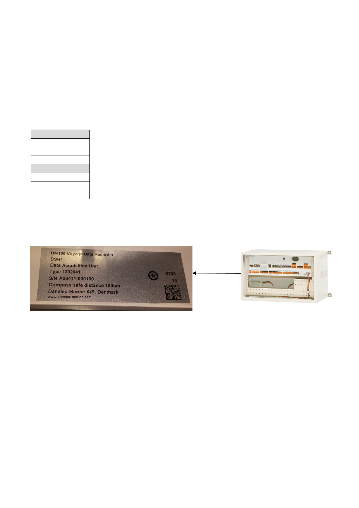
2 DANELEC S-VDR/VDR TYPES .................................................................................6
2.1 How to determine the S-VDR/VDR type .....................................................................6
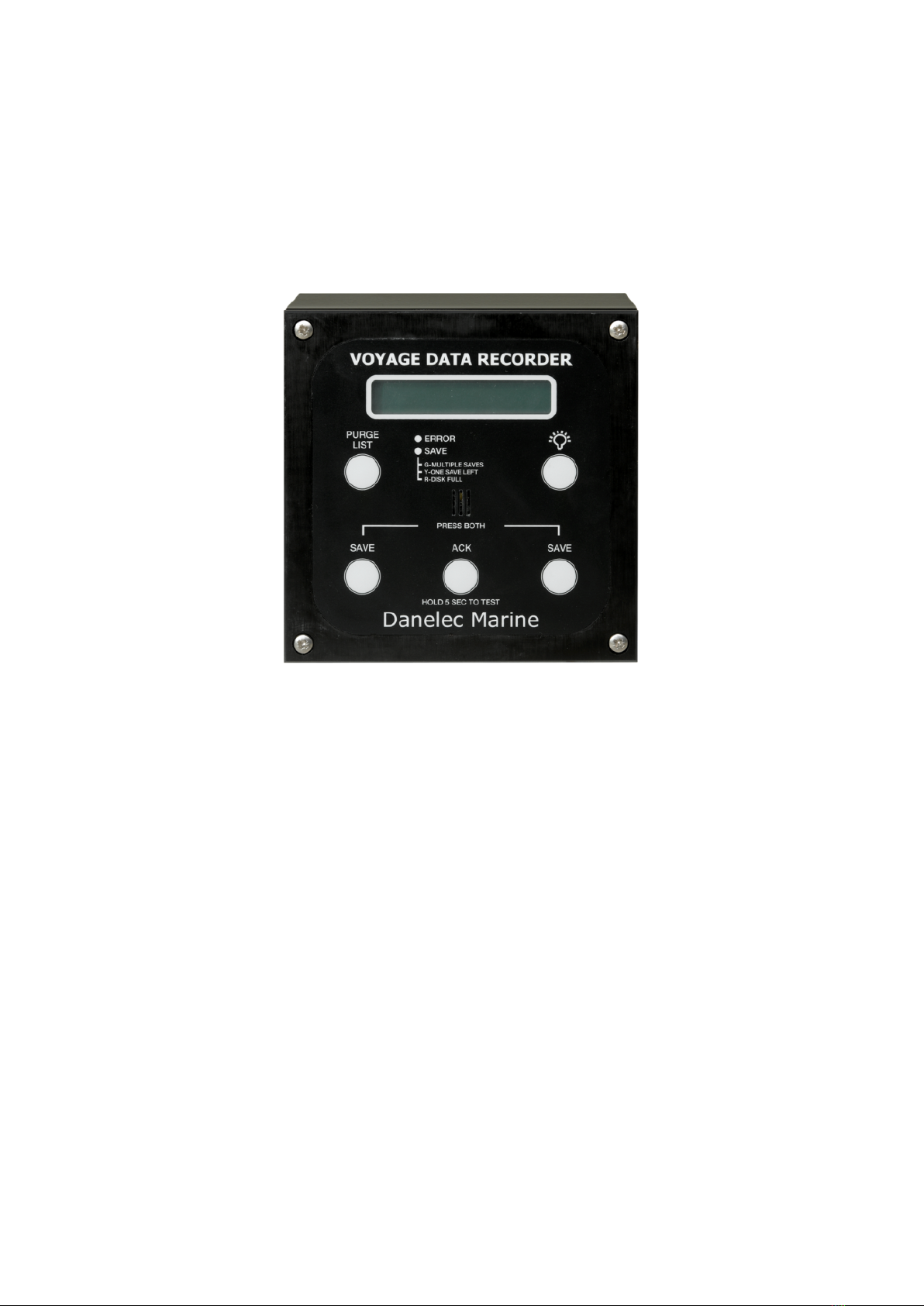
3 USER INTERFACE FOR DM100 / DM200 / DM300 S-VDR AND DM400 / 500 VDR
7
3.1 Dimmer button ............................................................................................................7
3.2 Alarms.........................................................................................................................7
3.3 Acknowledging alarm..................................................................................................8
3.4 Purging the alarm list ..................................................................................................8
3.5 Incidents......................................................................................................................8
3.6 Back up drive ..............................................................................................................9
3.7 How to save an incident..............................................................................................9
4 USER INTERFACE FOR DM100 VDR.....................................................................11
4.1 Dimmer button ..........................................................................................................11
4.2 Alerts.........................................................................................................................11
4.3 Menu .........................................................................................................................12
4.3.1 Audio test ...........................................................................................................13
4.3.2 Communication audio test..................................................................................13
4.3.3 Operational Performance Test ...........................................................................13
4.3.4 Performing an OPT ............................................................................................14
4.3.5 OPT report..........................................................................................................15
4.3.6 Network Data......................................................................................................17
4.3.7 System Info ........................................................................................................17
4.3.8 Analysis of recorded audio .................................................................................17
4.3.9 Download data to USB disk................................................................................18
5 HANDLING UNRESOLVED ALARMS.....................................................................19
6 CONNECTING A PC TO THE S-VDR/VDR .............................................................20
6.1 PC setup ...................................................................................................................20
6.2 Connecting the PC to the S-VDR/VDR .....................................................................23
6.3.1 DM200/DM300 S-VDR and DM400/DM500 VDR connection............................23
6.3.2 DM100 S-VDR and DM100 VDR connection .....................................................23
6.4 Log in to the S-VDR/VDR .........................................................................................24
7 EXTRACTING DATA FROM THE S-VDR/VDR USING A PC .................................25

Danelec Business System
Danelec Marine S-VDR/VDR USER GUIDE
Confidential. Copyright Danelec Marine A/S
DBS11343-11 Page 4/44
7.1 Data source: DM100/DM200/DM300 S-VDR and DM400/DM500 VDR ...............25
7.2 Data source: DM100 VDR .....................................................................................26
7.3 Extracting data.......................................................................................................27
8 EXTRACTING DATA TO AN USB DISK (DM100 VDR)..........................................29
9 EXTRACTING DATA FROM A NAS DISC ..............................................................31
9.1 NAS Setup.............................................................................................................31
9.2 Connecting to the NAS ..........................................................................................31
9.3 Exporting Data from NAS disc to file .....................................................................34
10 MAKE A DUMP FOR SUPPORT USING A PC .......................................................36
11 MAKE A DUMP FOR SUPPORT TO USB DRIVE (DM100 VDR) ...........................38
12 VDR EXPLORER......................................................................................................40
12.1 Starting VDR Explorer ........................................................................................40
12.2 Connecting to a data file.....................................................................................41
12.3 Play control.........................................................................................................42
12.4 Playing the data..................................................................................................43
12.5 Accessing the audio ...........................................................................................44
12.6 Vessel information..............................................................................................44

Danelec Business System
Danelec Marine S-VDR/VDR USER GUIDE
Confidential. Copyright Danelec Marine A/S
DBS11343-11 Page 5/44
1 Scope and purpose
This user guide describes all common tasks that the ship crew needs to perform on the Danelec
S-VDR/VDR. The user interface of all Danelec S-VDR/VDR is explained, as well as the procedure
to extract data from the S-VDR/VDR, and how to replay the extracted data.
1.1 References
User Manual for VDR Explorer - Document Number 9200294
Inspectors and Authorities Manual - Document Number 9200343
Manual for Network Attached Storage NAS 01-001- Document number DBS10903
1.2 Terms and Abbreviations
VDR Voyage Data Recorder
S-VDR Simplified Voyage Data Recorder
BCP Bridge Control Panel
BAU Bridge Alarm Unit
OPT Operation Performance Test
NAS Network Attached Storage
FRM Final Recording Media

Danelec Business System
Danelec Marine S-VDR/VDR USER GUIDE
Confidential. Copyright Danelec Marine A/S
DBS11343-11 Page 6/44
2 Danelec S-VDR/VDR types
The instructions given in this document covers all types of Danelec Marine S-VDR/VDR models.
Most instructions are similar regardless of the S-VDR/VDR type. However, there are some
differences. It is therefore necessary to determine what type of S-VDR/VDR is installed.
The following are the current and previous Danelec Marine S-VDR/VDR Models:
S-VDR
DM100 S-VDR
DM200 S-VDR
DM300 S-VDR
VDR
DM100 VDR
DM400 VDR
DM500 VDR
2.1 How to determine the S-VDR/VDR type
To determine what type of S-VDR / VDR is installed, open the S-VDR/VDR door and look for the
Type Approval label inside the cabinet. The label is located on the left-hand side of the cabinet.
Type approval label

Danelec Business System
Danelec Marine S-VDR/VDR USER GUIDE
Confidential. Copyright Danelec Marine A/S
DBS11343-11 Page 7/44
3 User Interface for DM100 / DM200 / DM300 S-VDR and
DM400 / 500 VDR
The user interface for the DM100/DM200/DM300 S-VDR and DM400/DM500 VDR is identical
and is called the Bridge Alarm Unit (BAU).
The BAU serves two purposes:
Alarm indicator and display
Saving of incidents to backup disk
In normal mode, the display of the BAU will indicate how many incidents are available in the
system. If alarms exist in the system, the display will indicate the alarm type.
3.1 Dimmer button
The Dimmer button can be used to adjust the backlight of the display and buttons. Press the dimmer
button multiple times to move between the different backlight levels.
3.2 Alarms
During normal operation, the S-VDR/VDR should not have any alarms and no user operation is
required.
If an alarm in the S-VDR/VDR occurs, the BAU will indicate the alarm in the following way:
The BAU buzzer will sound an alarm tone
The BAU display will indicate the alarm code (3 digit) and a short description
The ERROR LED will light up RED

Danelec Business System
Danelec Marine S-VDR/VDR USER GUIDE
Confidential. Copyright Danelec Marine A/S
DBS11343-11 Page 8/44
Alarm Example:
3.3 Acknowledging alarm
If an Alarm is present in the S-VDR/VDR, the BAU will sound the alarm tone. To stop the alarm
tone, press the ACK button.
After any alarm the system should be monitored to see whether the alarm has been automatically
cleared or persists in the system. As long as the ERROR LED is lit, an alarm is present in the
system.
An alarm in the system will be automatically cleared when the condition for the alarm disappears.
When all alarms are cleared, the ERROR LED will turn off and the display text will return to show
remaining incidents available.
3.4 Purging the alarm list
Pressing the PURGE LIST button will purge the alarm list of alarms where the alarm condition no
longer exists. If the condition for the alarm reappears, the alarm will sound again.
3.5 Incidents
In case of an incident, the crew of the vessel is required to save data onto the S-VDR/VDR backup
disk drive for later analysis.
The Danelec S-VDR/VDR contains a backup disk drive with data capacity for 3 incidents. When an
incident is saved, the S-VDR/VDR automatically stores the last 12 hours of recorded data on a
protected area of the backup disk drive while continuing to record new data.
When 3 incidents have been saved, the backup disk drive becomes full and no more incidents can
be saved. It is therefore important, after an incident has been saved, to extract data from the incident
onto another media (PC, CD, etc.) and delete the stored incident from the backup disk drive.
It is not recommended to use the save function as a form of backup for internal use. If backup of
recording for internal use is needed, the data should be extracted through the S-VDR/VDR web
interface as described in chapter 7.
Note:
Saved incidents can only be deleted by a certified Danelec Marine technician.30 days after the
incident was saved the write protection will be removed and the incident can be overwritten.
Alarm code
Short alarm description
ERROR LED is Red

Danelec Business System
Danelec Marine S-VDR/VDR USER GUIDE
Confidential. Copyright Danelec Marine A/S
DBS11343-11 Page 9/44
3.6 Back up drive
The Backup disk drive has been designed in accordance with IMO regulations to be easily
removable from the S-VDR/VDR in case of an emergency where the crew has to abandon the
vessel. The Backup disk drive should never be removed from the system under normal conditions.
Depending on the model, the backup disk drive is either a USB stick or a hard disk cassette.
S-VDR / VDR Type
Back up disk type
DM100 S-VDR
USB disk
DM200 S-VDR
USB disk
DM300 S-VDR
Hard disk cassette
DM400 VDR
USB disk
DM500 VDR
Hard disk cassette
Note:
The USB disk is not standard formatted. If connected to a computer, the computer may ask to
format it. DO NOT FORMAT THE USB DISC, all data will be lost and the S-VDR/ VDR will not
be able to record to it again. In case of a formatted USB disc, service is required.
3.7 How to save an incident
To save an incident, press the two save buttons on the BAU simultaneously. The display will
indicate that the backup procedure (saving the incident) is in progress and the SAVE LED will
blink. After saving the incident, press the ACK button to acknowledge and the display will return to
the main display.
USB disk
Hard disk Cassette
Press both save buttons
simultaneously
USB disk
Hard disk casette

Danelec Business System
Danelec Marine S-VDR/VDR USER GUIDE
Confidential. Copyright Danelec Marine A/S
DBS11343-11 Page 10/44
After each saving operation, the text in the display will change according to the table below.
Incident saved
Display text
SAVE LED
Display
0
Incidents Left (3)
Green
1
Incidents Left (2)
Green
2
Incidents Left (1)
Yellow
3
No Incidents Left
Red

Danelec Business System
Danelec Marine S-VDR/VDR USER GUIDE
Confidential. Copyright Danelec Marine A/S
DBS11343-11 Page 11/44
4 User Interface for DM100 VDR
The user interface of the Danelec DM100 VDR is called the Bridge Control Panel (BCP). The BCP
provides information about alarms (cautions) in the system, initiates tests, and displays system
information.
The BCP has 3 functions:
Indication of alarms (cautions) in the VDR system
Test interface for the VDR
Provision of system information and network data status
Two function buttons F1 and F2, and navigation buttons are used to navigate through the different
menus.
4.1 Dimmer button
The DIM button can be used to adjust the brightness of the display and buttons. Press the DIM
button to enter the menu and use left and right navigation buttons to adjust the brightness. Pressing
the F2 button while in the brightness menu will toggle between night or day mode.
4.2 Alerts
Unlike older S-VDR/VDR systems, the DM100 VDR does not provide any audible alarms. In
accordance with regulations, only visual indication of alarms on the BCP is provided. In addition,
alarms do not need to be acknowledged.

Danelec Business System
Danelec Marine S-VDR/VDR USER GUIDE
Confidential. Copyright Danelec Marine A/S
DBS11343-11 Page 12/44
When no alarms are present in the VDR, the main display only indicates VDR version and time.
The yellow caution LED will be off.
When an alarm is present, a yellow field will appear on the main display. The yellow field indicates
how many alarms are present in the system. As long as any alarms are present, the yellow caution
LED will be on.
Pressing the F1 button (alerts) will open the alerts screen. Here, a complete list of alarms currently
present in the VDR can be displayed. Each alarm has a 3 digit alarm code and a short description:
When an alarm is no longer present in the VDR, the alarm is removed from the Alert list on the
alert screen.
4.3 Menu
Pressing F2 button (Menu) opens the menu page where different tests can be initiated or system
information viewed.
The menu list contains:
Menu
Description
Audio test
Starts a microphone test.
Communication audio test
Starts a test of the VHF to VDR connection
Operational performance test (OPT)
Starts a new OPT test
View available operational performance
tests
Open previously performed OPT reports
Network data
Displays network data status
System info
Displays system information
Analysis of recorded audio
Analyses data disk usage
Download data to USB disk
Download extraction and dump for support to a USB disk
Alarm indication
Caution LED is on
Alarm indication
Caution LED is on
Alarm indication
Short alarm description
Alarm code

Danelec Business System
Danelec Marine S-VDR/VDR USER GUIDE
Confidential. Copyright Danelec Marine A/S
DBS11343-11 Page 13/44
4.3.1 Audio test
The audio test will initiate a microphone test. All microphone inputs on the VDR will be tested
using the built in buzzer in the microphones. After the test, a report will be generated indicating if
the connected microphones are working satisfactorily.
The report will indicate connected and configured microphones that are working correctly with a
green colour. Microphones that are configured but not working correctly will be indicated with a
yellow colour. Unused audio inputs will be shown as disabled.
4.3.2 Communication audio test
The communication audio test will test the VHF input to the VDR. After selecting communication
audio test, the BCP will now prompt the activation of the VHF connected to the VDR. The system
will detect when audio is present and make a short recording. If no audio is detected by the VDR,
an error message will appear.
After the test, the recorded audio is presented as a waveform picture. Here, the quality of the
recording can be evaluated.
4.3.3 Operational Performance Test
The OPT is a simplified VDR test that will verify the quality of all connected signals as well as
checking the final recording media (FRM) of the VDR. An OPT should be conducted on a regularly
scheduled basis to ensure that the VDR is working and recording correctly.
The OPT consist of the following test:
Test
Description
Final recording media
Verifies that the recording media are working and have recorded
continuously for the required period.
Audio test
Verifies all configured Microphones
Communication test
Verifies main and secondary VHF radio
Serial input test
Verifies all configured serial inputs
Analog input test
Verifies all configured analog signals
Digital test
Verifies all configured digital inputs
Image test
Verifies all configured image channels
The OPT is an automated process. After starting the OPT, the user will be prompted a few times in
order to carry out the communication audio test. The OPT will take a couple of minutes to
complete.
After the OPT has finished, an OPT report will be generated and displayed. The OPT report will
indicate any problems found during the test by highlighting the affected input with a yellow colour.
Some items such as communication audio and video are required to be verified by the user. In the
report it is therefore possible to view pictures of the communication audio and grabbed images from
the configured image sources.
Communication audio should be inspected for signs of constant noise. Images should be inspected
for clarity and correct resolution. Incorrect resolution will usually be seen on radar images where
the radar range rings are oval in shape.

Danelec Business System
Danelec Marine S-VDR/VDR USER GUIDE
Confidential. Copyright Danelec Marine A/S
DBS11343-11 Page 14/44
4.3.4 Performing an OPT
1. Click on F1 Button (“Menu”) and then select “ Start
new operational performance test (OPT)”.
2. Select which media to perform the OPT from.
3. The Communication Audio test will start. Click on
“OK” to start the test.
It is possible to skip the communication Audio test.
The BCP will now prompt the activation of the
communication audio channel within 60 seconds. At
this point, activate the VHF.
When the system detects audio on the channel, it will
start to record 15 seconds of audio.
After recording 15 seconds of audio, the system will
analyse the audio and if audio is present pass the test.
Click “OK” to continue.
If the test has failed (no audio present in the
recording), it is possible to restart the test by clicking
the F2 button (Retry).
The same test is performed for the secondary VHF channel if connected to the VDR.

Danelec Business System
Danelec Marine S-VDR/VDR USER GUIDE
Confidential. Copyright Danelec Marine A/S
DBS11343-11 Page 15/44
4. After the communication audio test, the OPT will
then automatically analyse Audio (bridge
microphones), serial, digital, analog and video data
recorded by the VDR.
5. After Analysing the data, the OPT report will be generated and displayed. See next
section for an explanation of the report.
4.3.5 OPT report
In “View available operational performance test” previously performed OPT reports can be viewed.
Additionally the OPT report will automatically be displayed after an OPT has been performed.
An OPT report consist of 8 pages.
General information
Display the vessel specific data including the expiry
date of the VDR backup batteries.
FRM Information
Display information about the final recording media
(FRM).
- Green colour indicates that the media is working
and has recorded for at least the period required
by regulation
- Yellow colour indicates a problem
- No colour indicates that the media has not yet been recording for the required period.
Bridge Audio
Display the result of the audio (Microphone) test.
- Green colour indicates that the microphone test
has passed.
- Yellow colour indicates an error.
- No colour indicates input is disabled (Unused).

Danelec Business System
Danelec Marine S-VDR/VDR USER GUIDE
Confidential. Copyright Danelec Marine A/S
DBS11343-11 Page 16/44
Communication audio
Display the result of the communication audio test.
- Green colour indicates microphone test has
passed.
- Yellow colour indicates an error.
It is possible to display the recorded audio by selecting the input and press the “OK”
button. A picture will appear displaying the audio waveform. The picture can be used to
evaluate if there is excessive noise etc. overlaying the audio.
Communication input
Display the result of the serial data input analysis.
All serial data that are configured to be recorded
will be displayed.
- Green colour indicates that the channel has
received the correct data.
- Yellow colour indicates an error or that the data
configured for this channel was not received e.g. transmitting device turned off.
Discrete Inputs
Display the result of the Digital input analysis. The
last recorded value of all digital input will be
shown.
- Green colour indicates channel is OK.
- Yellow colour indicates an error.

Danelec Business System
Danelec Marine S-VDR/VDR USER GUIDE
Confidential. Copyright Danelec Marine A/S
DBS11343-11 Page 17/44
Analog inputs
Display the result of the analog input analysis. The
last recorded value of all analog input will be
shown.
- Green colour indicates channel is OK.
- Yellow colour indicates an error
Image inputs
Display the result of the Image input analysis.
- Green colour indicates that a picture was
received
- Yellow colour indicates an error or that no
picture was received e.g. transmitting device
turned off.
It is possible to display the last recorded picture for each image channel by selecting the
image channel and press the “OK” button. The picture can now be evaluated for quality.
Pay special attention to resolution issues (picture looks stretched), picture sharpness and
whether the picture has captured the whole Radar/ECDIS display.
4.3.6 Network Data
The network data menu provides information about network errors etc. related to the VDR system.
It can be used to verify if a network problem exists.
4.3.7 System Info
This page provides information about the VDR model, Firmware version etc.
4.3.8 Analysis of recorded audio
This page provides an analysis of the last 15 seconds of recorded data. It is possible to see how
much of the storage has been used for Audio, Image, Serial, Analog, Digital and Log files. This
information may be helpful when troubleshooting storage issues.

Danelec Business System
Danelec Marine S-VDR/VDR USER GUIDE
Confidential. Copyright Danelec Marine A/S
DBS11343-11 Page 18/44
4.3.9 Download data to USB disk
This page allows the user to download either a VDR data extraction or a Dump for Support file. See
chapter 8 for a guide on how to extract data to a USB disk and chapter 11 for a guide of how to
make a dump for support file to a USB disk.

Danelec Business System
Danelec Marine S-VDR/VDR USER GUIDE
Confidential. Copyright Danelec Marine A/S
DBS11343-11 Page 19/44
5 Handling unresolved alarms
If an alarm persists in the S-VDR/VDR and is not cleared by itself or if the OPT report indicates
problems (DM100 VDR only), it must be assessed whether the alarm is critical and requires
support/service or whether it is due to an issue on board the vessel not related to the S-VDR/VDR,
but affects the data recorded by the S-VDR/VDR.
For example, if the radar connected to image channel 1 on the S-VDR/VDR is switched off, alarm
“080 VIDEO VD01 input” will appear. When the radar is switched on again, the alarm will
automatically disappear. If the radar was not switched off and the same alarm appears, it indicates a
connection or hardware problem. In this case, service is required.
Some alarms may take a while to disappear from the system, even though the condition that caused
the alarm has been corrected. On all systems with a BAU, pressing the “Purge List” button will
clear the alarms from the system immediately and the alarm will only reappear if the condition for
the alarm still exists. On systems with a BCP, this possibility does not exist. This means that the
system must be monitored if an alarm remains after the condition has been corrected.
In the event of an alarm that requires service, contact one of Danelec Marine’s agents. A list of
agents can be found on the Danelec Marine web page:
http://www.danelec-marine.com
Danelec Marine may in some cases request a dump for support file to be sent to Danelec for
analysis. In this case, please see section 10 for instructions on how to perform a dump for support.

Danelec Business System
Danelec Marine S-VDR/VDR USER GUIDE
Confidential. Copyright Danelec Marine A/S
DBS11343-11 Page 20/44
6 Connecting a PC to the S-VDR/VDR
6.1 PC setup
The PC is used to extract data from the S-VDR / VDR. Before connecting the PC to the
S-VDR/VDR the network interface of the PC must be configured. The default IP address of the
S-VDR/VDR is 10.0.0.100, Subnet mask 255.255.255.0. To connect to the S-VDR/VDR, the PC
network adaptor must be set to an IP address in the same range.
The recommended IP address for the PC is, IP address: 10.0.0.10, Subnet mask 255.255.255.0.
Note:
If the IP address of the VDR has been changed to another value than the default, the PC network
adaptor must be configured accordingly.
Note:
The IP address of the computer may not be the same as the IP address of the S-VDR/VDR.
Follow these steps to configure the PC:
1. Open the network and sharing menu in the control panel
Click Start menu →Control Panel
2. In the control panel click on Network and Sharing center
3. In the Network and Sharing Center window click on Change adapter Settings
This manual suits for next models
5
Table of contents
Popular Marine Equipment manuals by other brands

Pittway
Pittway SYSTEM SENSOR SpectrAlert CH12/24 Installation and maintenance instructions

Furuno
Furuno FE-700 Operator's guide

C.Nord
C.Nord Rielta CN-Siren quick start guide

JRC
JRC Alphatron Marine Mode Switch 3 Pos Operation manual

Yacht Devices
Yacht Devices YDTC-13 user manual

Apollo
Apollo 45681-266 installation guide

Guidance Navigation
Guidance Navigation RadaScan Operator's guide

Lewmar
Lewmar AutoAnchor 550 Operation manual

Garmin
Garmin LIVESCOPE installation instructions

Furuno
Furuno GP-1810F installation manual

COBHAM
COBHAM Sea Tel 120 TVHD Field Installation & Test Procedure

ZF Marine
ZF Marine ZF 286 Series manual