FireClass FC430SB User manual

ITALIANO
SPECIFICHE TECNICHE
Valore Identificativo: 130
Compatibilità: usare solo con Centrali serie FC
Caratteristiche ambientali: Solo per applicazioni interne
Temperatura di funzionamento: da -25 a +70 oC
Temperatura di stoccaggio: da -40 a +80 oC
Umidità relativa:fino a 95% (senza condensa)
Dimensioni:
Altezza
(inclusa staffa di montaggio):
Diametro:
Peso:
37,5 mm
110 mm
0,186 Kg
Requisiti di montaggio: a parete o su una scatola elettrica
adeguata con passo dei fori da 50
a 70 mm, con staffa da 4".
Caratteristiche elettriche:
A riposo:
In allarme:
200 µA tipico
6,8 mA al volume massimo (90 dBA)
1,2 mA al volume minimo (68 dBA)
!ATTENZIONE: ASSICURARSI CHE IL PIANO DEL SITO
DEFINISCA LE POLARITÀ DELLE BASI CON POLARITÀ
CONOSCIUTA.
Compatibilità Elettromagnetica
Il modulo FC430SB è conforme a quanto segue:
Øfamiglia di prodotto standard EN50130-4 rispetto alle Perturba-
zioni Dirette, Immunità Irradiata, Scarica Elettrostatica, Transi-
torie Rapide e Alta Energia Lenta;
ØEN 61000-6-3 per le emissioni.
ENGLISH
TECHNICAL SPECIFICATION
TypeIdentificationValue: 130
System Compatibility: use only with FC Fire Alarm Controllers
Environment: Indoor Application only
Operating Temperature: -25 to +70 oC
Storage Temperature: -40 to +80 oC
Operating Humidity: Up to 95% non-condensing
Dimensions:
Height
(including mounting flange):
Diameter:
Weight:
37.5 mm
110 mm
0.186 Kg
Mounting Requirements: Flat surface or suitable electrical
backbox with 50 to 70 mm fixing cen-
tres with the 4" flange.
Electrical Characteristics:
Standby:
Alarm:
200 µA typical
6.8 mA at full volume (90 dBA)
1.2 mA at low volume (68 dBA)
!CAUTION: ENSURE THAT SITE PLAN DEFINES THE
POLARITY OF POLARITY CONSCIOUS BASES.
Electromagnetic Compatibility
The FC430SB complies with the following:
Øproduct family standard EN50130-4 in respect of Conducted
Disturbances, Radiated Immunity, Electrostatic Discharge,
Fast Transients and Slow High Energy;
ØEN61000-6-3 for emissions.
Base Avvisatore Acustico Alimentata da Loop FC430SB FIG. 1FC430SB Loop Low Power Sounder Base
FC430SB
BASE AVVISATORE ACUSTICO ALIMENTATA DA LOOP
LOOP LOW POWER SOUNDER BASE
ISTISBL3FC430SB 1.0 250208
FireClass

INTRODUCTION
The FC430SB Loop Low Power Sounder Base provides an addi-
tional sounder function on the FC addressable loop circuit. The
FC430SB Loop Low Sounder Base requires an associated detec-
tor in order to operate, as it uses the address of the detector that is
fitted to it. Removal of the detector or loss of power to the loop will
cause the sounder to cease operating. A maximum of 45 Sounder
Bases at full volume may be connected to the loop.
FEATURES
The FC430SB provides eight tone and variable volume settings.
WIRING NOTES
The following notes apply.
1) All wiring must conform to the applicable standards.
2) All wiring must be free of earths.
SETTING SOUNDER OUTPUT OPTIONS
The sounder outputs are set as follows:
ØTone – using the 4-way DIL switch (Fig. 3 and Table 1 refer).
ØVolume – using the trimmer tool (FC490VA) (Fig. 3 refers).
INTRODUZIONE
La Base Avvisatore Acustico Alimentata da Loop FC430SB fornisce
una funzione sonora addizionale sul circuito a loop indirizzabile FC.
La Base Avvisatore Acustico Alimentata da Loop FC430SB deve
essere abbinata ad un rilevatore per funzionare, perchè usa l'indiriz-
zo del rilevatore sul quale è fissata. La rimozione del rilevatore o la
perdita dell'alimentazione del loop farà cessare di funzionare la
Base Avvisatore Acustico. Un massimo di 45 Basi Avvisatore Acu-
stico, al massimo volume, possono essere collegate al loop.
CARATTERISTICHE
Il FC430SB fornisce otto tonalità e la regolazione del volume.
NOTE PER IL COLLEGAMENTO
Osservare le seguenti note.
1) I collegamenti devono essere conformi alle norme applicabili.
2) Nessun conduttore deve essere collegato a terra.
IMPOSTAZIONE DELLA BASE AVVISATORE ACUSTICO
La Base Avvisatore Acustico si imposta come segue.
ØTono – tramite gli interruttori DIL a 4 vie (vedere Fig. 3 e Tab. 1).
ØVolume – tramite lo strumento di regolazione (FC490VA) (ve-
dere Fig. 3).
DALLA CENTRALE O
DISPOSITIVO PRECEDENTE
FROM CONTROLLER OR
PREVIOUS DEVICE
ALLA CENTRALE O DISPOSITIVO
SEGUENTE
TO NEXT DEVICE OR CONTROLLER
Coonnessioni alla base sonora FC430SB FIG. 2Connections to FC430SB Sounder Bases
INTERRUTTORI PER SELEZIONE TONO
TONE SELECTION SWITCHES REGOLATORE VOLUME
(RUOTARE IN SENSO ANTIORARIO PER DIMINUIRE IL VOLUME)
VOLUME ADJUSTOR
(ANTI-CLOCKWISE TO DECREASE VOLUME)
IL POTENZIOMETRO DI REGOLAZIONE DEL VOLUME È COPERTO
DA UN’ETICHETTA ADESIVA BIANCA (RIMUOVERE L’ETICHETTA
SE È NECESSARIO REGOLARE IL VOLUME).
DOPO LA REGOLAZIONE DEL VOLUME RIATTACCARE
L’ETICHETTA. SE L’ETICHETTA È DANNEGGIATA SOSTITUIRLA
CON UNA NUOVA.
THE POT ADJUSTER IS COVERED BY A VOLUME POT BLANK
LABEL (ONLY TO BE REMOVED IF VOLUME TO BE REDUCED).
THE LABEL MUST BE REFITTED AFTER ANY ADJUSTMENT. IF
THE LABEL IS DAMAGED IT MUST BE REPLACED BY A NEW
ONE.
STRUMENTO PER LA REGOLAZIONE DEL VOLUME
VOLUME TRIMMER TOOL
FIG.3Base Avvisatore Acustico FC430SB
FC430SB Sounder Base
Olandese / Dutch
Temporale 4* / Temporal 4*
Rampa Lenta* / Slow Sweep*
Suono a Tempo di Marcia* / March Time Beep*
Rampa Veloce / Fast Sweep
Temporale 3 / Temporal 3
Doppio tono* / Two Tone*
Continuo* / Continuos*
IMPOSTAZIONI INTERRUTTORI DIL / DIL SWITCHS SETTINGS
SUONO CORRISPONDENTE
RESPONSE SOUND
N. Tono Marketing
Marketing Tone No.
TAB. 1*)Questi toni non sono approvati LPCB.
*) These tones are not LPCB approved

INSTALLAZIONE A PARETE O SU SCATOLA ELETTRICA
Per installare la Base Avvisatore Acustico procedere come segue.
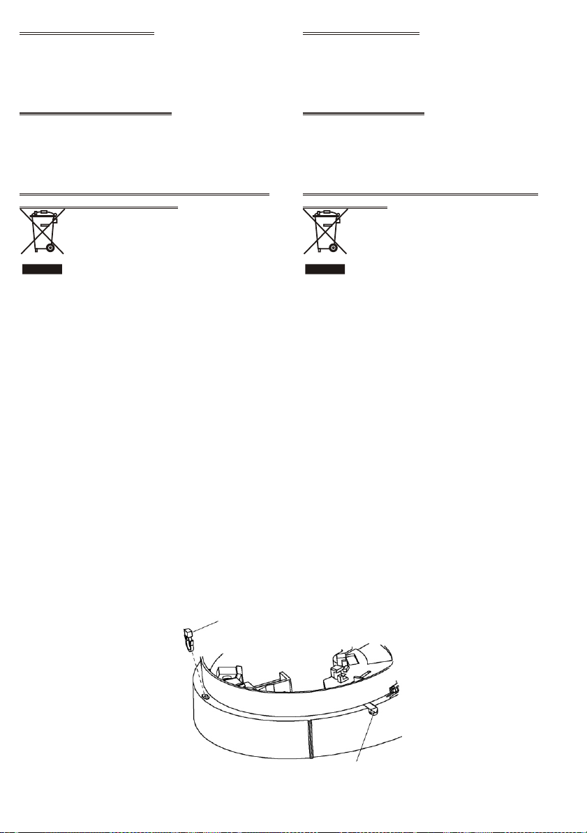
1) Passare i fili relativi al loop indirizzabile attraverso l'ingresso
dei cavi della staffa di montaggio.
2) Fissare la staffa di montaggio alla scatola elettrica o alla parete
come richiesto.
3) Passare i fili relativi al loop indirizzabile attraverso l'ingresso
dei cavi della Base Avvisatore Acustico, quindi agganciare la
Base alla staffa di montaggio.
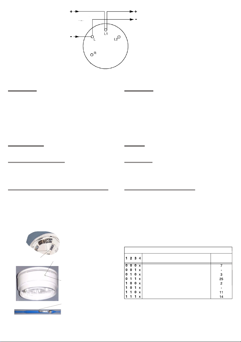
4) Collegare la Base Avvisatore Acustico come mostrato in Fig. 2
rispettando la corrretta polarità.
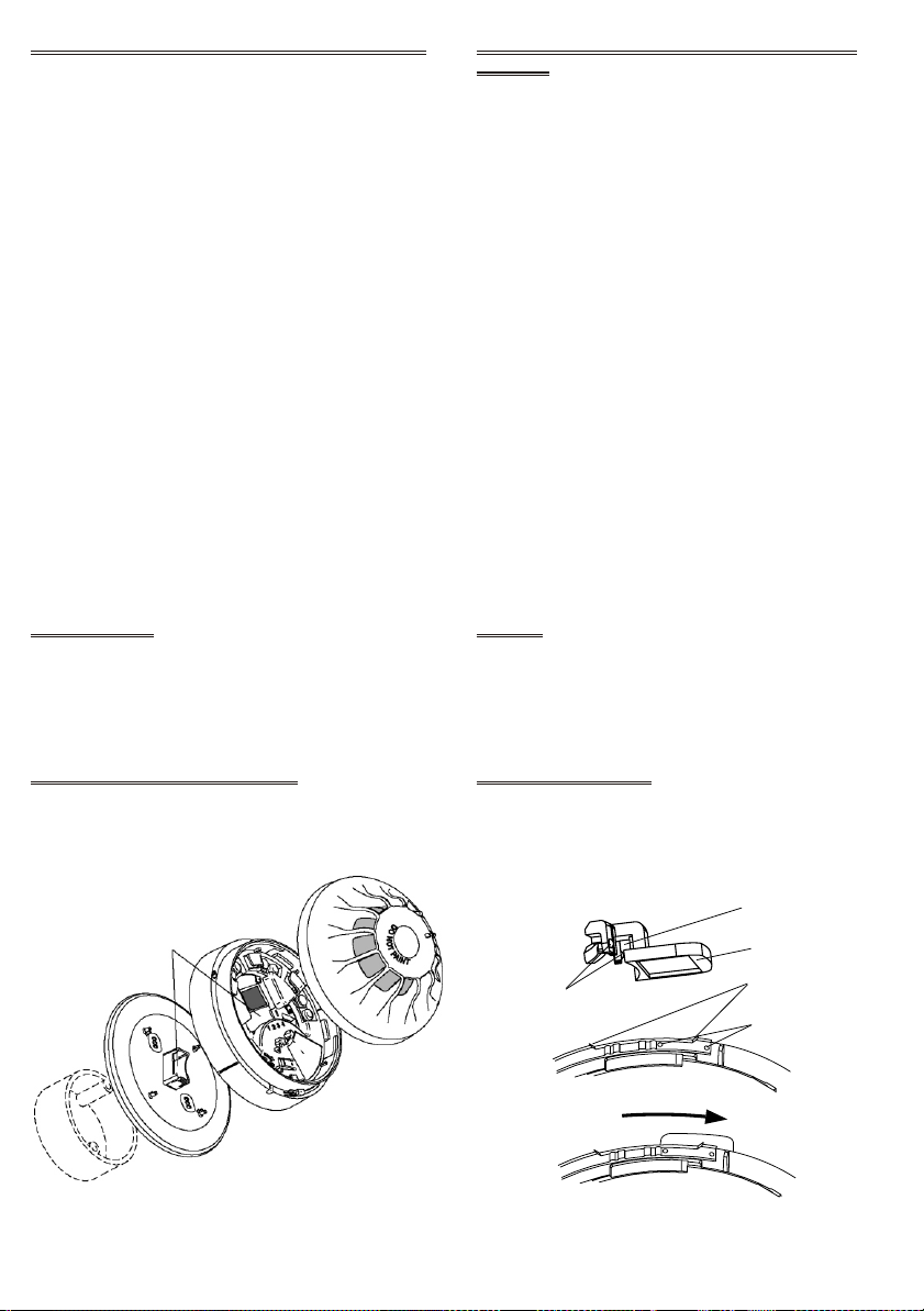
5) Inserire la linguetta dell'indirizzo nel rilevatore (vedere Fig. 5).
6) Fissare il rilevatore alla Base Avvisatore Acustico, (la linguetta
dell'indirizzo sarà trasferita alla Base Avvisatore Acustico).
!NON RIEMPIRE LO SPAZIO TRA LA STAFFA DI
MONTAGGIO E LA BASE AVVISATORE ACUSTICO.
!NON COLLEGARE ALCUN FILO ESTERNO AL
TERMINALE L2.
+Nota: per l'approvazione LPCB, i rilelvatori e le calotte devono
essere bloccati alla Base Avvisatore Acustico tramite un dispo-
sitivo di bloccaggio (fornito di fabbrica). Assicurarsi che il di-
spositivo di bloccaggio sia in posizione prima di fissare un
rilevatore o un cappuccio. Vedere Fig. 6. L'etichetta per l'Aper-
tura del Potenziometro del Volume deve essere attaccata.
COLLEGAMENTO
I cavi devono essere selezionati in conformità con il documento di
progettazione e nel rispetto delle norme applicabili. La sezione
massima del cavo collegabile ad ogni morsetto è di 2,5 mm2. La
sezione và calcolata in base alle caratteristiche del cavo e del cari-
co.
CONFIGURAZIONE DELLA CENTRALE
Quando la Base Avvisatore Acustico è fissata ad un rilevatore in-
dirizzabile le opzioni della Base devono essere impostate nella
configurazione del rilevatore.
INSTALLATION TO A FLAT SURFACE OR ELECTRICAL
BACKBOX
To install a sounder base, proceed as follows.
1) Feed the addressable loop wiring through the mounting flange
cable entry.
2) Secure the mounting flange to either an electrical backbox or a
flat surface as required.
3) Feed the addressable loop wiring through the sounder base
cable entry, then clip the sounder base to the mounting flange.
4) Wire the sounder base as shown in Fig. 2 ensuring correct po-
larity.
5) Fit the address flag to the detector, see Fig.5.
6) Fit the detector to the sounder base, (the address flag will be
transferred to the sounder base).
!DO NOT FILL SOUND GAP BETWEEN MOUNTING
FLANGE AND SOUNDER BASE.
!DO NOT CONNECT ANY EXTERNAL WIRING TO
CONNECTION L2.
+Note: for LPCB approval, detectors and caps must be locked
into the sounder base using a locking device (Factory fitted). En-
sure that the locking device is in place before fitting a detector or
cap. See Fig. 6. The Volume Pot Blank Label must be fitted.
CABLING
Cables are to be selected in accordance with the system design
document and the requirements of the applicable standards. The
maximum section of the cable that can be connected at any one
terminal is 2.5mm2.The section is calculated based on the character-
istics of the cable and the load.
PANEL CONFIGURATION
When a Sounder Base unit is attached to on addressable detector,
the Sounder Base option must be set in the detector configuration.
INGRESSO CAVO
CABLE ENTRY
RILEVATORE
DETECTOR
BASE AVVISATORE ACUSTICO
SOUNDER BASE
STAFFA DI MONTAGGIO
MOUNTING FLANGE
SCATOLA ELETTRICA
ELECTRICAL BACKBOX
FIG. 4Installazione a parete o su una scatola elettrica
Installation to a flat surface or electrical backbox
INCAVI DI BLOCCAGGIO
RETAINING DEPRESSIONS
RIENTRANZA DI MONTAGGIO
MOUNTING RECESS
PARTE SAGOMATAA ´D`
´D` SHAPED PART
CANALE SAGOMATO A ´U`
´U` SHAPED CHANNEL
SPORGENZE DI BLOCCAGGIO
RETAINING PIMPLES
FIG. 5Inserimento della Linguetta Indirizzo
Fitting Address Label Carrier

ORDERING INFORMATION
FC430SB: Low Power Sounder Base.
FC490VA: Volume Adjustment Trimmer Tool.
Volume Pot Blank Label (Sheet of 144).
RECYCLING INFORMATION
Customers are recommeded to dispose of their used equipments
(panels, detectors, sirens, and other devices) in an environmentally
sound manner. Potential methods include reuse of parts or whole
products and recycling of products, components, and/or materials.
WASTE ELECTRICAL AND ELECTRONIC EQUIPMENT
(WEEE) DIRECTIVE
In the European Union, this label indicates that this
product should NOT be disposed of with household
waste. It should be deposited at an appropriate facility
to enable recovery and recycling.
The manufacturer reserves the right to change the technical speci-
fications of this product without prior notice.
INFORMAZIONI PER L'ORDINE
FC430SB: Base Avvisatore Acustico Alimentata da Loop.
FC490VA: Strumento per la Regolazione del Volume.
Etichetta per l'Apertura del Potenziometro del Volume.
(Foglio da 144 etichette)
INFORMAZIONI SUL RICICLAGGIO
Si consiglia ai clienti di smaltire i dispositivi usati (centrali, rilevato-
ri, sirene, accessori elettronici, ecc.) nel rispetto dell'ambiente.
Metodi potenziali comprendono il riutilizzo di parti o di prodotti inte-
ri e il riciclaggio di prodotti, componenti e/o materiali.
DIRETTIVA RIFIUTI DI APPARECCHIATURE ELETTRICHE
ED ELETTRONICHE (RAEE - WEEE)
Nell'Unione Europea, questa etichetta indica che que-
sto prodotto NON deve essere smaltito insieme ai ri-
fiuti domestici. Deve essere depositato in un impianto
adeguato che sia in grado di eseguire operazioni di re-
cupero e riciclaggio.
Il costruttore si riserva il diritto di modificare le specifiche tecniche
di questo prodotto senza preavviso.
PERNO PER IL PARCHEGGIO TEMPORANEO
TEMPORARY PARK PLUNGER
DISPOSITIVO DI BLOCCAGGIO
LOCKING DEVICE
Dispositivo di Bloccaggio e Perno per il Parcheggio Temporaneo FIG. 6Locking Device and Temporary Park Plunger
Other FireClass Marine Equipment manuals