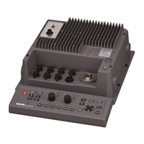
CVS-872D Contents
0092607062-01 v
Contents
Document Revision History.......................................................................................................................i
Important Notice.......................................................................................................................................ii
For Your Safe Operation.........................................................................................................................iii
Contents....................................................................................................................................................
...................................................................................................................................................v
System Configuration.............................................................................................................................vii
Configuration of Equipment...................................................................................................................viii
Characteristics of Transducer................................................................................................................ xiii
Dimensions............................................................................................................................................xiv
Specifications .........................................................................................................................................xv
Chapter 1 Installation …………………………………………………………………….1-1
1.1 Installation precautions..........................................................................................................1-1
1.1.1 Unpacking of components..................................................................................................... 1-1
1.1.2 Appearance verification of each unit and accessories ..........................................................1-1
1.1.3 Selection of location for installation .......................................................................................1-1
1.1.4 Laying and connection of cables ...........................................................................................1-2
1.1.5 Coordination after installation................................................................................................ 1-2
1.2 Installation of CVS-872D Display unit.................................................................................... 1-3
1.2.1 Desk-top installation...............................................................................................................1-3
1.2.2 Flush-mount installation......................................................................................................... 1-5
1.3 Installation of transducer........................................................................................................1-6
1.3.1 Cautions on installation of transducer.................................................................................... 1-6
1.3.2 Precautions regarding transducer installation .......................................................................1-7
1.3.3 In the case of inner hull installation........................................................................................ 1-8
1.4 Wiring...................................................................................................................................1-26
1.4.1 Connection of cables to Display unit.................................................................................... 1-26
1.5Connection of Hemisphere V102/V104s/V200s GPS Compass / ComNav Vector G1 GPS
Satellite Compass................................................................................................................1-53
1.5.1 Connection of Hemisphere V102/V104s/V200s GPS Compass / ComNav Vector G1 GPS
Satellite Compass................................................................................................................1-53
1.5.2 Connection of Hemisphere V104s GPS Compass..............................................................1-58
1.5.3 Connection of Hemisphere V200s GPS Compass..............................................................1-63
1.5.4 Setting of Hemisphere V102/V104s/V200s GPS Compass / ComNav Vector G1 GPS
Satellite Compass................................................................................................................1-68
1.6List of input/output sentences.............................................................................................. 1-74
1.6.1 Input sentence .....................................................................................................................1-74
1.6.2 Output sentence................................................................................................................... 1-74
1.6.3 Input/Output sentence details.............................................................................................. 1-75
Chapter 2 Adjustment …………………………………………………………………….2-1
2.1 Setup of transducer................................................................................................................ 2-1
2.1.1 Setup of type of transducer.................................................................................................... 2-1
2.2 Setup of frequency and beam angle...................................................................................... 2-2
2.3 Setup of Bottom Limit.............................................................................................................2-3
2.4 Setup of Draft Set ..................................................................................................................2-3
2.5 Setup of Gain (TD) for transducer .........................................................................................2-3
2.6 Setup of Output Limit for transmitter...................................................................................... 2-4
2.6.1 Display of Output Limit Menu................................................................................................. 2-4
2.6.2 Relation of the set value between [Output Limit] and [MENU] - [EchoAdjust] - [TX Power]
...............................................................................................................................................2-5
Chapter 3 Maintenance ………………………………………………………………..3-1
3.1 Inspection............................................................................................................................... 3-1
3.2 Cleaning.................................................................................................................................3-1
