DekTec DTM-3200 User manual


DTM-3200 – OEM Ethernet TSoIP Converter
User Manual
2
Table of Contents
Firmware Revision History ........................................................................................................ 4
1. Introduction ........................................................................................................................ 6
1.1 General description ....................................................................................................... 6
1.2 TSoIP-to-ASI mode ......................................................................................................... 6
1.3 ASI-to-TSoIP mode .........................................................................................................
1.4 Control .........................................................................................................................
1.5 DTM-3200 protocol handler ...........................................................................................
1.6 Theory of operation ....................................................................................................... 8
1.6.1 IP-to-ASI converter - Functional block diagram .......................................................... 8
1.6.2 ASI-to-IP converter mode - Functional block diagram ................................................ 9
1. List of abbreviations ....................................................................................................... 9
1.8 References .................................................................................................................. 10
2. Getting Started ................................................................................................................. 11
2.1 Introduction ................................................................................................................. 11
2.2 Configuration #1: Converting TSoIP to ASI ..................................................................... 11
2.2.1 Test set-up .......................................................................................................... 11
2.2.2 Configuring the TSoIP to ASI conversion ................................................................. 11
2.3 Configuration #2: Converting ASI to TSoIP ..................................................................... 12
2.3.1 Test set-up .......................................................................................................... 12
2.3.2 Configuring the ASI to TSoIP conversion ................................................................. 12
3. Layout and Installation....................................................................................................... 13
3.1 Physical layout ............................................................................................................. 13
3.2 Mechanical dimensions ................................................................................................ 13
3.3 Order codes ................................................................................................................ 14
3.4 Hardware installation ................................................................................................... 14
3.4.1 Mechanical installation ......................................................................................... 14
3.4.2 ASI connector ...................................................................................................... 14
3.4.3 Parallel-TS connector ........................................................................................... 14
3.4.4 DIP switches ........................................................................................................ 15
3.4.5 Control connector ................................................................................................ 16
3.4.6 Ethernet connector ............................................................................................... 1
3.4. Power connector .................................................................................................. 1
3.4.8 Stream status LED ................................................................................................ 18
3.4.9 DTM-3200 status LED .......................................................................................... 18
4. Device Configuration and Monitoring.................................................................................. 19
4.1 Control interfaces ........................................................................................................ 19
4.2 Command protocol ...................................................................................................... 19
4.2.1 Command protocol on RS-232 / RS-422 / RS-485 .................................................. 19
4.2.2 Command protocol on I
2C.................................................................................... 20
4.3 Manageable items ....................................................................................................... 21
4.4 Categories .................................................................................................................. 22
4.4.1 Data types .......................................................................................................... 22

DTM-3200 – OEM Ethernet TSoIP Converter
User Manual
3
4.4.2 Device properties ................................................................................................. 22
4.4.3 Overall configuration ........................................................................................... 23
4.4.4 Network settings .................................................................................................. 23
4.4.5 Firmware update ................................................................................................. 24
4.4.6 IP receive settings ................................................................................................. 25
4.4. IP transmit settings ............................................................................................... 2
4.4.8 ASI input settings ................................................................................................. 29
4.4.9 ASI output settings................................................................................................ 29
4.5 Firmware upgrade ....................................................................................................... 30
4.5.1 Firmware upgrade - Phases .................................................................................. 30
4.5.2 Firmware upload – Example.................................................................................. 31
4.5.3 Binary data to Ascii data function .......................................................................... 31
4.6 Failsafe mode.............................................................................................................. 32
5. Specifications .................................................................................................................... 33
5.1 Network connection ..................................................................................................... 33
5.2 DVB-ASI input/output ................................................................................................... 33
5.3 Parallel port input/output .............................................................................................. 33
5.4 Transport-Stream input/output over IP ............................................................................ 34
5.5 Serial control port ........................................................................................................ 35
5.6 I
2C control port ............................................................................................................ 35
5. Other specifications ..................................................................................................... 35
Appendix A. Mechanical Dimensions...................................................................................... 36
Appendix B. DTM-3200 Development Kit................................................................................ 3
Appendix C. Command-Line Tool - DtmCmd .......................................................................... 39
Appendix D. Communication Example .................................................................................... 41
Copyright © 2010-2014 by DekTec Digital Video B.V.
DekTec Digital Video B.V. reserves the right to change products or specifications without notice.
Information furnished in this document is believed to be accurate and reliable, but DekTec assumes
no responsibility for any errors that may appear in this material.

DTM-3200 – OEM Ethernet TSoIP Converter
User Manual
4
Firmware Revision Histor
Version Date Changes
2.3 2014.10.0 Important notice for upgrading to firmware version v2.3:
An upgrade to firmware version 2.3 is only possible if the firmware version of
your DTM-3200 is v2.0 or higher. If the current firmware version is older than
v2.0, please first upgrade the unit to v2.0.
Changes:
Firmware update v2.3 adds an item to the ASI input settings category: this allows
one to force the module to use a specific input port. The default (which can be
chosen as well) is to auto-detect which input has a signal.
Bug fixes:
IGMP/multicast issue seen after 49 days
Possible failure to sync to ASI input stream
Several other small improvements and bug-fixes
2.2 2013.0 .11 Important notice for upgrading to firmware version v2.2:
Firmware update v2.2 contains both application and failsafe firmware. Any
interruption of the upgrade process may result in an unusable DTM-3200
module.
An upgrade to firmware version 2.2 is only possible if the firmware version of
your DTM-3200 is v2.0 or v2.1. If the current firmware version is older than
v2.0, please first upgrade the unit to v2.0.
Bug fixes:
Fix for failsafe firmware not starting correctly in specific cases
2.1 2012.10.12 Important notice for upgrading to firmware version v2.1:
An upgrade to firmware version 2.1 is only possible if the firmware version of your
DTM-3200 is v2.0. If the current firmware version is older than v2.0, please first
upgrade the unit to v2.0.
Bug fixes:
Ignore a reboot command while the device is rebooting
Stability fixes in the rate estimation algorithm
2.0 2012.03.28 Important notice for upgrading to firmware version v2.0:
Firmware update v2.0 contains both application and failsafe firmware. Any
interruption of the upgrade process may result in an unusable DTM-3200 module.
The first boot after this update will take longer than usual, this is normal behavior.
Fixed issues:
DTM-3200 unicasts to all ports of a switching hub
Category 0x81, setting 0x14 'PCR present' does not work
Category 0x81, setting 0x15 'Rate change counter': value is incorrect
Category 0x81, setting 0x19 ‘Delay factor’: value is incorrect
Corruption of IP packet headers leading to occasional packet loss
DHCP client is started twice
The serial command protocol is case-sensitive, should be case insensitive
After extensive communication and reboot the application firmware may get
corrupted
Dtm3200Util user interface locks up when repeatedly sending a setting to
category 0x82, while no Ethernet cable has been attached
Fixed issues related to I2C control:
Accessing other I2C devices while DTM-3200 is processing a command causes

DTM-3200 – OEM Ethernet TSoIP Converter
User Manual
5
the DTM-3200 to become unresponsive
DTM-3200 does not generate an I2C error response when an incorrect
command has been issued
DIP switches #3 and #4 have no effect when used to set I2C slave address
An I2C master has to wait at least 10ms between issuing a command and trying
to read the response
Changes affecting customer design:
The I2C read behavior has changed: The DTM-3200 will always acknowledge
its address when a read-cycle is initiated. When there is no data available to
return to the master, zeroes will be returned. This also means that zeroes are
appended to a message when the master reads more bytes than available
The firmware update ASCII encoding (does not apply to I2C) has been altered
and is incompatible with previous versions, including older failsafe firmware
Enabling the DHCP client by writing an IP address with value 0.0.0.0 is no
longer supported. Writing 0.0.0.0 will result in an error-response, since it is an
incorrect fixed IP address. The user should use the DHCP-enable setting instead
Every message sent by the DTM-3200 on the RS-XXX port now uses uppercase
ASCII characters. Users checking for lowercase characters should change this to
uppercase. e.g. "3A" instead of "3a", "R" instead of "r"
Other changes:
Added 'VBR' mode, category 0x81, setting 0x16, data 0x03
Changed behavior of the DHCP enable setting (category 0x03, setting 0x04)
Added 'Volatile Storage' setting (category 0x02, setting 0x03), giving the user the
option to choose between RAM or FLASH storage of settings
Added checking for 'r' and 'R' in the read/write-field of a command message.
Previously any character other than 'w' or 'W' would result in a read reply
Added protocol checks for incorrect settings; these will result in an 'E' reply
Removed automatic reboot at the end of the firmware update process
Firmware update speed has been improved, compressed programming files are
now supported and ASCII encoding has been altered
MPEG null packets (PID 8191) are now ignored when scanning for PCRs, to
prevent incorrect detection of PCRs resulting in lock errors
1.0 2010.03.31 Initial release to the field
DTM-3200 – OEM Ethernet TSoIP Converter
User Manual
6
1. Introduction
1.1 General description
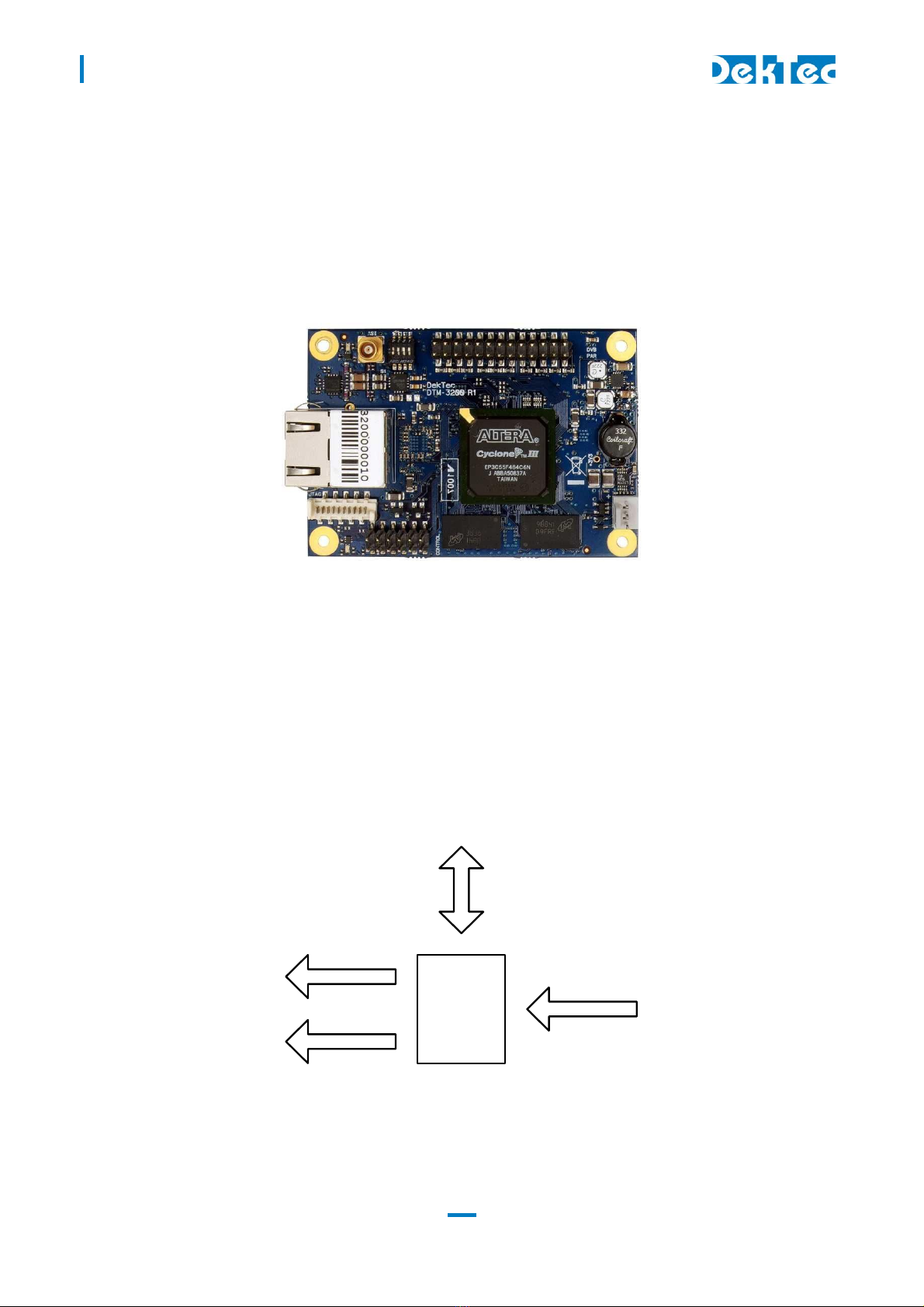
The DTM-3200 is a compact OEM module to convert ASI to or from a Transport Stream over IP
(TS-over-IP or TSoIP). Next to the serial ASI interface, the unit supports a parallel interface. The
direction of the conversion (TSoIP to ASI or ASI to TSoIP) can be configured programmatically
through the control interface.
Figure 1. The PCB of the DTM-3200
The DTM-3200 is available in two models and a development kit (see also §3.3):
DTM-3200 with standard pin headers (power connector is right-angle type);
DTM-3200-RA with right-angle pin headers;
DTM-3200-DEVKIT: DTM-3200 with power supply and cables.
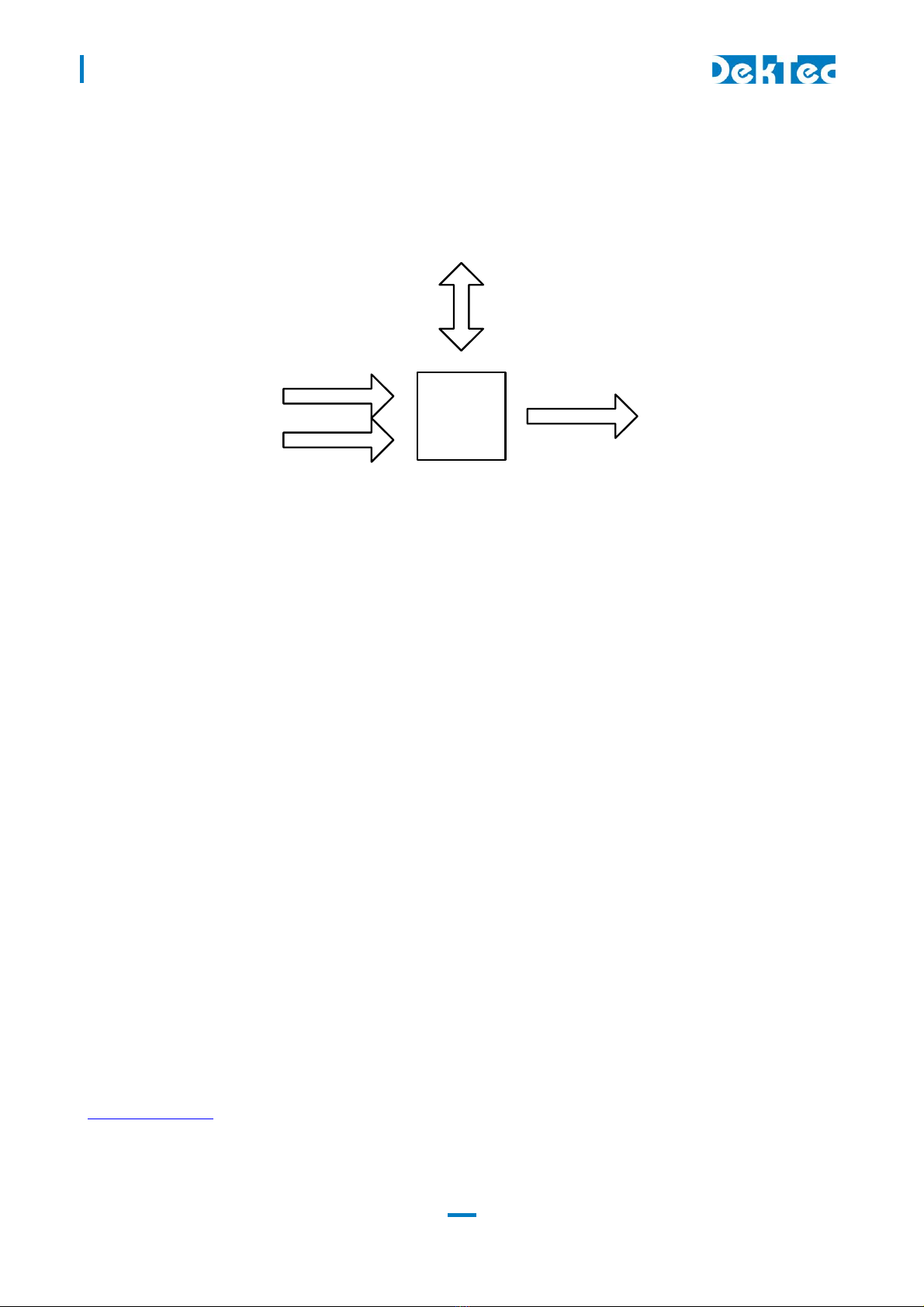
1.2 TSoIP-to-ASI mode
When configured as TSoIP-to-ASI converter, the unit accepts unicast and multicast streams over its
Gigabit-Ethernet port. Key features include de-encapsulation of UDP or RTP, IP jitter removal and
error correction according to SMPTE 2022-1. The resulting stream is transmitted simultaneously on
the ASI output connector and the parallel pin header.
Control
TSoIP
DVB-ASI
DVB-SPI
DTM-3200
Figure 2. The DTM-3200 configured as IP-to-ASI converter
DTM-3200 – OEM Ethernet TSoIP Converter
User Manual
1.3 ASI-to-TSoIP mode
When configured as ASI-to-TSoIP converter, the DTM-3200 accepts ASI or parallel input. The ASI
input is selected automatically when a signal is available; otherwise the parallel input is used. Key
features include encapsulation of UDP or RTP, controlled scheduling of IP packets to prevent IP jitter
(zero jitter playout), and adding forward error correction (FEC) according to SMPTE 2022-1.
Control
TSoIP
DVB-ASI
DTM-3200
DVB-SPI
Figure 3. The DTM-3200 configured as ASI-to-IP converter
1.4 Control
The unit can be managed and controlled through one of the available control interfaces: I
2C or
RS-232/485/422. Settings applied through one of the control interfaces can be stored in non-
volatile memory (if setting Volatile storage is ‘1’) or in volatile memory (if setting Volatile storage is
‘0’) on the unit. Settings stored in non-volatile memory are automatically reloaded after a power
cycle. It is not possible to configure the device via the Ethernet interface.
There are three ways to control the DTM-3200:
1. From a development PC using the serial RS-232 control interface. This way of controlling can
be used for pre-configuring the DTM-3200, or for experimenting with the DTM-3200.
2. Using a controller on-board of the equipment that uses the DTM-3200 for I/O conversion. In
this case I
2C is a plausible choice, but the other serial interfaces may also be used.
3. Stand-alone mode. The DTM-3200 is pre-configured and no dynamic control is applied.
Two test tools are available:
1. Dtm3200Util – Windows GUI tool to view status and control settings of the DTM-3200. The
tool can also be used to upload firmware. Dtm3200Util is convenient for initial configuration
of the DTM-323 and for experimentation with the DTM-3200.
2. DtmCmd – Command-line tool to send commands to the DTM-3200. Multiple commands can
be combined in a script to apply a group of settings in one go. DtmCmd is useful for studying
the low-level commands available for the DTM-3200. It is also useful to apply a pre-defined
group of setting values from a script.
1.5 DTM-3200 protocol handler
An open source implementation of a protocol handler for DTM-32xx devices is available from
www.dektec.com free of charge. It consists of two source files, DtmHandler.c and
DtmHandler.h, which can be compiled and linked into your C or C++ application. Please refer to
DtmHandler.h for information about how to use the protocol handler in your application.

DTM-3200 – OEM Ethernet TSoIP Converter
User Manual
8
Note:
Command-line tool DtmCmd is an example of an application that uses the DTM handler. The
source of DtmCmd is also available on the DekTec website.
1.6 Theor of operation
Essentially, the DTM-3200 consists of two subsystems:
A Stream Processor, which converts the IP packets to a base-band Transport Stream and
outputs it as ASI and parallel, or vice versa;
A processor subsystem that handles all internal and external control (I
2C, RS232/485/422).
The DTM-3200 is operating either as IP-to-ASI converter, or as ASI-to-IP converter.
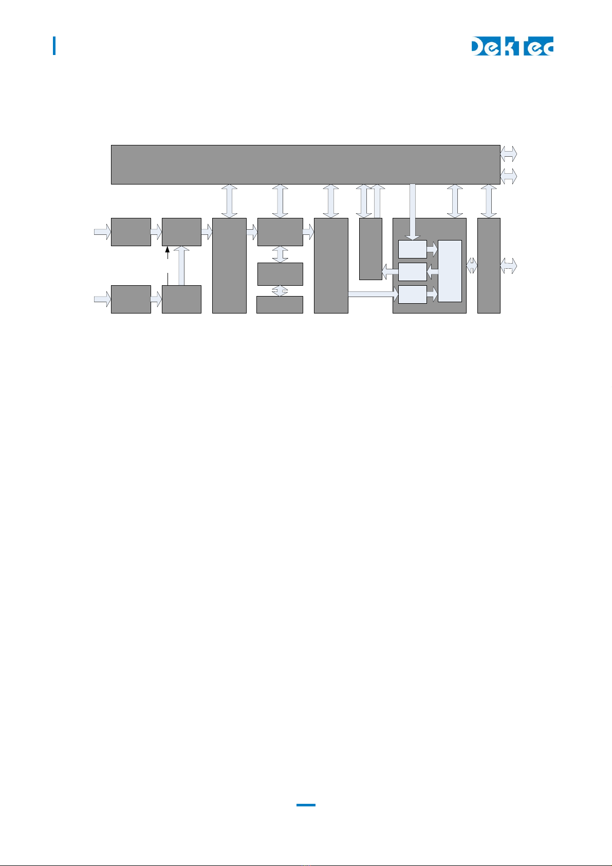
1.6.1 IP-to-ASI converter - Functional block diagram
Figure 4 shows the functional block diagram of the DTM-3200 when it is configured as IP-to-ASI
converter.
TS
Transmit
Channel
Processor Subsystem
IP DATA
IP
Filter
FEC
reconstructor
Bitrate control
LVDS buffer
IP
to
TS
ETHERNET
INTERFACE
MAC
IP
Transmit-
ter
IP
eceiver
IP DATA
DDR
SDRAM
Controller
DDR
SDRAM
Phy
Stream
characte-
ristics
extractor
Cable driver
Serializer
S232 or
S485 or
S422
I2C
DVB-SPI
DVB-ASI
CONT OL
Ethernet
CONT OL
CONT OL
CONT OL
CONT OL
CONT OL
Figure 4: Functional block diagram of the DTM-3200 when configured as IP-to-ASI converter
The incoming Ethernet packets are received by the physical layer interface (PHY). The Ethernet
interface checks the packets for corruption and correctness, and sends them to the IP filter that
selects the desired stream. Other IP packets are sent to the processor subsystem in order to support
low-level IP protocols like ARP and DHCP. From the IP Filter the transport stream data enters the
stream characteristics extractor. This block will analyze the stream for specific characteristics like PCR
information. With these characteristics, the DTM-3200 determines the bitrate for transmitting the
stream at the output. The FEC Reconstructor uses the FEC streams (if available) to reconstruct
missing packets (if any).
In the next step, the data is stored in SDRAM. Jitter on the IP input stream may cause late arrival of
some IP packets. The memory is used as a buffer to ‘de-jitter’ the stream. The size of the de-jitter
buffer can be set via the control interface. The IP stream is then converted to a Transport Stream (TS)
with the correct bitrate. The resulting stream is transmitted as an ASI and as a parallel stream at the
same time. The TS contents are not affected by the DTM-3200.
DTM-3200 – OEM Ethernet TSoIP Converter
User Manual
9
1.6.2 ASI-to-IP converter mode - Functional block diagram
Figure 5 shows the functional block diagram of the DTM-3200 when it is configured as ASI-to-IP
converter.
TS
Receive
Channel
Processor Subsystem
IP DATA
IP
Filter
FEC
generator
LVDS
receiver
ETHERNET
INTERFACE
MAC
IP
Transmit-
ter
IP
eceiver
IP DATA
DDR
SDRAM
Controller
DDR
SDRAM
Phy
IP
Embed-
der
Cable
equaliser
De-
serializer
S232 or
S485 or
S422
I2C
DVB-SPI
DVB-ASI
CONT OL
Ethernet
CONT OL
CONT OL
CONT OL
CONT OL
CONT OL
IP
Transmit-
ter
Intput
select
Valid
Figure 5: Functional block diagram of the DTM-3200 when configured as ASI-to-IP converter
The incoming stream is received either through the serial or the parallel input. Only one stream can
be received at a time. If the Deserializer detects a valid input stream, the Input Selector selects the
DVB-ASI input, otherwise the Input Selector selects the parallel input. The TS Receive Channel
synchronizes to the stream and determines the packet size (188 or 204 bytes). If the DTM-3200 is
configured to generate FEC packets, the FEC Generator will create row and column FEC data. The
IP Embedder embeds the TS packets in IP packets. Finally, the PHY transmits the IP packets through
the Ethernet interface.
1.7 List of abbreviations
ASI Asynchronous Serial Interface. Shorthand for DVB-ASI.
auto-MDIX Automatic medium-dependent interface crossover. Technique to
automatically detect the type of network cable: straight-through or
crossover.
DHCP Dynamic Host Configuration Protocol. Network protocol to automatically
assign an IP address to a network port from a server.
DVB Digital Video Broadcasting
FEC Forward Error Correction
IP Internet Protocol
MAC Media Access Controller
Mbps Megabit per second
NA Not Applicable
NC Not Connected
PCR Program Clock Reference
R/W Read / Write
RO Read Only

DTM-3200 – OEM Ethernet TSoIP Converter
User Manual
10
RTP Real-time Transport Protocol
SPI Synchronous Parallel Interface. Shorthand for DVB-SPI.
TSoIP Transport Stream over IP
UDP User Datagram Protocol
WO Write Only
1.8 References
[1] SMPTE-2022-1, Forward Error Correction for Real-Time Video/Audio Transport Over IP
Networks
[2] SMPTE-2022-2, Unidirectional Transport of Constant Bit Rate MPEG-2 Transport Streams
on IP Networks

DTM-3200 – OEM Ethernet TSoIP Converter
User Manual
11
2. Getting Started
2.1 Introduction
This section provides a walkthrough for getting started with the DTM-3200. Two set-ups are
described: one for receiving a Transport Stream over IP (TSoIP) and converting it to ASI, and one the
other way around, receiving ASI and converting it to TSoIP.
The description below assumes that the DTM-3200 development kit (see Appendix B) is used to
control the DTM-3200 over USB from a development PC. The GUI tool Dtm3200Util is used to
apply settings and observe status.
2.2 Configuration #1: Converting TSoIP to ASI
This set-up will receive a TSoIP stream and transmit the stream on the ASI interface.
2.2.1 Test set-up
For testing this configuration, a TSoIP transmitter
1 should be present on the network to generate a
TSoIP test signal. To observe the output of the DTM-3200, an ASI receiver is helpful.
This tutorial assumes that the network dynamically assigns IP addresses through DHCP, and that the
source generates a TSoIP stream with the following parameters:
Protocol UDP
Destination address 224.1.1.1
UDP Port 56 8
2.2.2 Configuring the TSoIP to ASI conversion
Using Dtm3200Util, configure the DTM-3200 as shown in the table below. The receive process is
first disabled before changing configuration parameters. When all parameters have been set, the
DTM-3200 is enabled again.
Category Setting Value
1 0x81: IP receive 2: Enable 0 = Off
2 0x81: IP receive 1: Addressing method 1 = Multicast
3 0x81: IP receive 4: FEC enable 0 = Off
4 0x81: IP receive 10: UDP port 56 8
5 0x81: IP receive 11: IP-to-Output delay 100 = 100ms
6 0x81: IP receive 12: Multicast address 224.1.1.1
0x84: ASI/par. output 1: Packet size 0 = 188-byte MPEG-2 packets
8 0x81: IP receive 2: Enable 1 = On
1 If you do not have a suitable TSoIP transmitter and/or ASI receiver, this functionality can for example be realized with a
PC and a DekTec DTA-2160 I/O card in it. Please consult your local DekTec representative for more information.

DTM-3200 – OEM Ethernet TSoIP Converter
User Manual
12
The DTM-3200 will now receive a TSoIP stream and transmit this stream on the ASI port. The status
LED will be green to indicate successful transmission of the TS on the ASI output. If no TSoIP stream
is received, the status LED will be red.
2.3 Configuration #2: Converting ASI to TSoIP
This set-up will receive a stream on the ASI interface and transmit the stream over IP.
2.3.1 Test set-up
The equipment and tools are similar to the ones listed in §2.2.1 In this case we need an external ASI
source and a TSoIP receiver on the network.
2.3.2 Configuring the ASI to TSoIP conversion
The settings below (sequential order) set up the DTM-3200 for ASI to IP conversion. No FEC will be
generated in this example.
Category Setting Value
1 0x82: IP transmit 1: Enable 0 = Off
2 0x82: IP transmit 3: FEC Enable 0 = Off
3 0x82: IP transmit 6: IP Address 224.1.1.1
4 0x82: IP transmit 8: UDP Port 56 8
5 0x82: IP transmit 9: #TP per IP 3 = 3 Transport Packets per IP pckt
6 0x82: IP transmit 10: Protocol 0 = UDP
0x82: IP transmit 13: Time to Live 100
8 0x83: ASI/par. input 1: Packet Size 0 = 188-byte MPEG-2 packets
9 0x82: IP transmit 1: Enable 1 = On

DTM-3200 – OEM Ethernet TSoIP Converter
User Manual
13
3. La out and Installation
3.1 Ph sical la out
DTM-3200
(top-view)
5
2 3 1
4
8
7
1
111
2
2
12
1 2 3 425
26
6
on
1
3
9
10
1 ASI I/O MCX 5Ω ASI input or output
2 Parallel TS 26-pin box
header
2.54mm pitch
Parallel Transport Stream input or output;
Similar to DVB-SPI, but with fixed 2 -MHz clock
instead of TS clock
3 Switches DIP Selection of baud rate and control interface:
RS-232 or RS-485/422
4 Control 12-pin header
2.54mm pitch
RS-232 (DCE), RS-485/422 and I
2C interface for
board control
5 Ethernet RJ-45 Ethernet port for TS-over-IP transmission or
reception
6 Identifier Type and revision number
Power Power and reset
8 Factory Factory program connector;
Not used in normal operation
9 Stream status Stream status LED
10 DTM-3200 status DTM-3200 Status LED
3.2 Mechanical dimensions
See Appendix A.
DTM-3200 – OEM Ethernet TSoIP Converter
User Manual
14
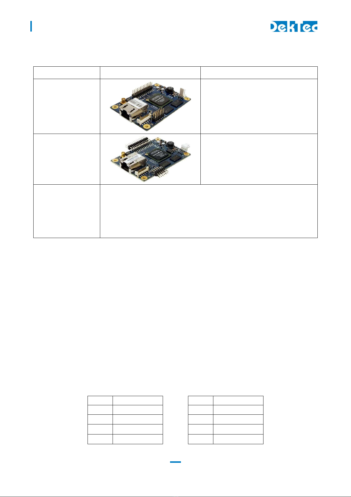
3.3 Order codes
Order Code Picture Description
DTM-3200
Model with standard pin headers
Note: The photo shows a power connector
with straight pins, but on current production
a right-angle power connector is used, like
on DTM-3200-RA
DTM-3200-RA
Model with right-angle pin headers
DTM-3200-DEVKIT The DTM-3200 development kit contains the following items:
DTM-3200 placed on four plastic studs
DTM-3200-USB-INTERFACE board
10V/1.2A power supply
USB cable type A to mini B
MCX to BNC cable assembly with a length of 130 mm
3.4 Hardware installation
3.4.1 Mechanical installation
The unit can be mounted onto a support plate by means of four 2.5 mm bolts and appropriate
spacers. Ensure that there is sufficient airflow to provide cooling of the board.
3.4.2 ASI connector
The ASI connector (1) is an MCX connector with an impedance of 5 ohm.
3.4.3 Parallel-TS connector
The pinning of the parallel Transport-Stream connector (2) is displayed in the table below. The
signal levels and pin numbering the same as DVB-SPI.
Warning: Although the pinning is the same, the parallel interface is not compatible with DVB-SPI,
because the clock of the DTM-3200’s parallel interface is fixed to 2 MHz (in DVB-SPI the clock is the
TS rate in byte/sec).
Pin Signal Pin Signal
1 DCLK+ 2 DCLK-
3 GND 4 GND
5 D + 6 D -
D6+ 8 D6-
DTM-3200 – OEM Ethernet TSoIP Converter
User Manual
15
9 D5+ 10 D5-
11 D4+ 12 D4-
13 D3+ 14 D3-
15 D2+ 16 D2-
1 D1+ 18 D1-
19 D0+ 20 D0-
21 DVALID+ 22 DVALID-
23 PSYNC+ 24 PSYNC-
25 GND 26 GND
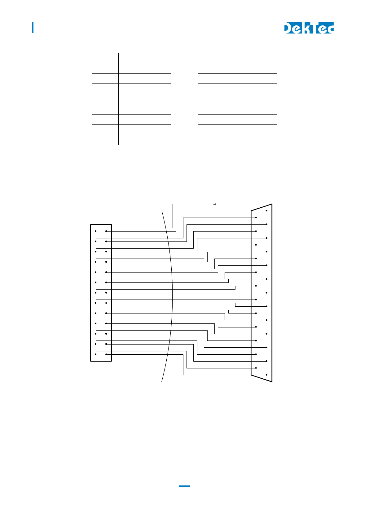
The pin assignment of the pin header has been chosen in such a way that a flatcable with a sub-D
male flatcable connector (25-way sub-D; ISO 2110) at the other end can be connected directly to
the board.
26-pin female header flatcable 25-pin male sub-D
3.4.4 DIP switches
The DIP switches permit configuration of I
2C device address, RS-232 or RS-485/422 mode and the
baud rate. The state of the DIP switches is read at power up only. Changing the DIP switch settings
while power is on has no effect.
25
24
23
22
21
20
19
18
17
16
15
14
13
12
11
10
9
8
7
6
5
4
3
2
1
26
24
22
20
18
16
14
12
10
8
6
4
2
25
23
21
19
17
15
13
11
9
7
5
3
1
NC

DTM-3200 – OEM Ethernet TSoIP Converter
User Manual
16
Please note that it is not required to select between I
2C and RS-XXX: The DTM-3200 will
automatically use the interface on which it detects activity.
DIP switches for RS-232/485/422
For RS-232 or RS-485/422, the DIP switches have the following meaning:
Switch # Description
1 Device address bit 0 – LSB (off = 0, on = 1)
2 Device address bit 1 – MSB (off = 0, on = 1)
3 RS-232 or RS-485/422 (off = RS-232; on = RS-485/422)
4 Baud-rate (off = 9600; on = 115200)
The device address bits are used for RS-485/422 only. The device address is 0x40 + two LSBs as
selected by the DIP switches. This means that the device address range is between 0x40 and 0x43.
DIP switches for I
2C
For I
2C communication, the DIP switches have the following meaning:
Switch # Description
4, 3, 2, 1 Device address bit 3..0 (DIP switch off = 0, on = 1)
The I
2C device address is 0x40 + four LSBs as selected by the DIP switches. This means that the I
2C
device address range is between 0x40 and 0x4F.
3.4.5 Control connector
The pinning of the control connector is shown in the table below. It’s a single row pin header for
connecting the RS-232 (DCE), RS-485/422 or I
2C control bus. The exact function of the signals
depends on whether RS-232 or RS-485/422 mode is selected by the DIP switches.
Pin RS-232 mode (DCE) RS-485/422 mode
1 NC NC
2 NC NC
3 TX TX/RX-
4 CTS NC
5 RX NC
6 RTS TX/RX+
NC NC
8 NC NC
9 GND GND
10 NC NC
11 SDA SDA
12 SCL SCL
The pinning of this connector has been chosen in such a way that a 9-way flatcable with a press-fit
sub-D flatcable connector can be connected directly to pin 1 – 9, see the figure below.

DTM-3200 – OEM Ethernet TSoIP Converter
User Manual
1
12-pin female header 9-pin female sub-D
An I
2C controller can be connected to SDA and SCL on pin 11 and 12, with signal ground on pin 9.
3.4.6 Ethernet connector
The Ethernet connector is a standard shielded RJ45 jack with two status LEDs.
Link speed LED
Orange 1000Mbps
Green 10 or 100Mbps (half duplex)
Off No signal
The link-activity LED flashes whenever an Ethernet packet is received or transmitted.
A standard Cat5E (or higher) patch cable can be used to connect the DTM-3200 to a network. Either
a straight-through or cross-over network cable can be used; the type of cable will be automatically
recognized (auto-MDIX operation). The DTM-3200 will automatically select the link speed of the
connected network (10/100/1000Mbps).
3.4.7 Power connector
The DTM-3200 must be powered from an external source with a voltage between 6V and 24V DC.
Power consumption is max. 5W. The pinning of the power connector is shown in the table below:
Pin Description
1 Positive power connection
2 Ground
3 Reset connection
The board can be reset by connecting pin 3 to ground for at least 100ms. The connector type is the
Molex KK series 2.54 mm pitch.
12
10
8
6
4
2
11
9
7
5
3
1
9
8
7
6
5
4
3
2
1

DTM-3200 – OEM Ethernet TSoIP Converter
User Manual
18
3.4.8 Stream status LED
This LED indicates the status of the ASI and parallel stream. The following colors are used for status
indication:
ASI output mode
Short red/green flashes No output generated on ASI and parallel outputs
Red/green Generating live output on ASI and parallel outputs
Note: When the ‘Rate Estimation’ (category 0x81, setting 0x16) is set to 3, bitrate estimation in the
DTM-3200 is turned off and the stream status LED will always be Red/green.
ASI input mode
Short green flashes No carrier detected on ASI or parallel input
Long green flashes Carrier detected but no data on ASI or parallel input
Green Valid signal detected on ASI or parallel input
Red Erroneous signal detected on ASI or parallel input
3.4.9 DTM-3200 status LED
This LED indicates the current status of the DTM-3200. The following colors are used for status
indication:
Red Running in failsafe mode
Red/green Booting
Green Running in operational mode

DTM-3200 – OEM Ethernet TSoIP Converter
User Manual
19
4. Device Configuration and Monitoring
4.1 Control interfaces
The DTM-3200 can be configured and monitored using I
2C, RS-232 (DCE), RS-485 or RS-422. DIP
switch #3 selects between RS-232 and RS-422 or RS-485. It is not required to select between I
2C
and RS-XXX: The DTM-3200 will automatically use the interface on which it detects activity.
All control interfaces use the same command and response protocol that is described below.
4.2 Command protocol
Commands and responses are wrapped into a frame structure that contains address, category,
setting, read/write, index (optional) and data (optional). The DTM-3200 accepts uppercase and
lowercase characters, but will always respond in uppercase.
4.2.1 Command protocol on RS-232 / RS-422 / RS-485
Field Format Description
Start ASCII character
STX (0x02)
ASCII “start of text” character
Address 2 hex digits
2 8-bit address, with the 6 MSBs fixed to 0x40 and the 2 LSBs
configurable using DIP switches 1 and 2
Category 2 hex digits Selects a “category” of settings
Setting 2 hex digits Selects a setting within the selected category
Read/Write ASCII character
‘R’ or ‘W’
‘R’ for read and ‘W’ for write
Index 4 hex digits (Optional) Provides an extra index parameter, e.g. to
indicate the channel number
3
Data n hex digits / n
ASCII
characters
4
The data written or read. The data length is variable for
each setting. In case of a write operation, the data is a
(negative) acknowledgement
Checksum 2 hex digits This is the least significant byte of the two’s complement
5
sum of all characters in the message, excluding the STX and
ETX characters and the checksum itself
End ASCII character
ETX (0x03)
2 Hex digits are the ASCII characters 0…9 and A…F, concatenated to form a single hexadecimal value.
3 The DTM-3200 supports a single channel only, so index is used as a channel number, it’s always 0.
4 Since firmware version 1.4 the firmware update setting uses ASCII characters 128 to 255 for sending the firmware data.
5 Invert all bits and add one.

DTM-3200 – OEM Ethernet TSoIP Converter
User Manual
20
Figure 6 below shows the structure of a command written through the serial interface. If the
command is a read-command, the data may be omitted. If the category does not require an index,
the index must be omitted.
Figure 6. Command on an RS-XXX serial control interface
All commands successfully sent to the DTM-3200 are answered with a copy of the command
including the data bytes.
When an incorrect checksum is detected, the DTM-3200 will not return an answer. When protocol
errors are detected, e.g. a combination of a valid category with an invalid setting, the R/W byte of
the reply is replaced with the ASCII character ‘E’ and the data is removed from the message.
4.2.2 Command protocol on I 2C
Field Format Description
Start S Standard I
2C start condition
Address I2C address byte -bit I
2C address followed by the I
2C R/W bit, which is set to
0 and 1 in the command- and response sequence
respectively
Category 1 byte Selects a “category” of settings
Setting 1 byte Selects a setting within the selected category
Read/Write 1 byte 0x01 for read and 0x00 for write
Index 2 bytes (Optional) Provides an extra index parameter, e.g. to
indicate the channel number
6
Data n bytes The data written or read. The data length is variable for
each setting. In case of a write operation, the actual data is
returned as a (negative) acknowledgement
Checksum 1 byte This is the least significant byte of the two's complement of
the sum of the -bit I2C slave address and all data-bytes in
the I2C message (excluding the checksum). The I2C R/W bit
is not included, an incorrect value of this bit would cause the
checksum to be not received at all.
End P Standard I
2C stop condition. A repeated start condition can
be used at all times to concatenate multiple I
2C read / write
actions
6 The DTM-3200 supports a single channel only. Whenever index is used as a channel number, it shall/will be set to 0.
Table of contents
Other DekTec Media Converter manuals


