manuals.online logo
Brands
  1. Home
  2. •
  3. Brands
  4. •
  5. Del ozone
  6. •
  7. Oxygen Equipment
  8. •
  9. Del ozone EC-AG1 User manual

Del ozone EC-AG1 User manual

IMPORTANT SAFETY INSTRUCTIONS
1. Read and Follow All Instructions
2. Read this manual completely before attempting installation.
3. All permanent electrical connections should be made by a qualified electrician.
4. Connect to a grounding type receptacle only. If the ozone generator electrical connection
is to be attached to the pool controls, be sure the pool controls are protected by a Ground
Fault Circuit Interrupter (G.F.C.I.). If the ozone generator is connected to an independent
electrical supply, then a G.F.C.I. must be installed between the ozone generator and the
electrical supply.
5. Do not bury cord.
6. Warning - To reduce the risk of electrical shock, replace damaged cord
immediately.
7. Install at least 5 feet (1.5 meters) from wall of pool. Install ozone generator
no less than one (1) foot above maximum water level to prevent water
from contacting electrical equipment. Install in accordance with the
installation instructions.
8. Follow all applicable electrical codes.
9. Electric shock hazard. Be sure to turn power OFF and disconnect from
power source before any service work is performed. Failure to do so could
result in serious injury or death.
10. The ozone generator must be installed in an outdoor location, or indoors
in a forced air ventilated room, and installed so that the orientation is
exactly as shown in Figure 1.
11. Mount the ozone generator so that it is inaccessible to anyone in the pool.
Never attempt any servicing while unit is wet.
12. Plastic ozone supply tubing is supplied with the ozone generator. Never
replace this tubing with metal tubing.
13. Warning - Short-term inhalation of high concentrations of ozone and long
term inhalation of low concentrations of ozone can cause serious harmful
physiological effects. DO NOT inhale ozone gas produced by this device.
14. For your safety, do not store or use gasoline, chemicals or other flammable
liquids or vapors near this or any other appliance.
SAVE THESE INSTRUCTIONS.
2
EC-AG1, EC-AG2
EC-AG1-25
EC-AGX Installation & Operation Manual
After this information is provided, DEL Ozone will release a RETURN GOODS
AUTHORIZATION (RGA) NUMBER. After receiving the RGA number the part in
question must be returned to DEL Ozone, freight prepaid, with the RGA number
clearly marked on the outside of the package. All preauthorized defective parts
must be returned to DEL Ozone within thirty (30) days. Under no circumstances
may any product be returned to DEL Ozone without prior authorization. You must
call or write DEL Ozone prior to returning product or your returned goods ship-
ment will be refused. Upon receipt of preauthorized returned goods, DEL Ozone
will repair or replace, at DEL Ozone’s option, the defective product(s) and return
them freight (prepaid for products under warranty). Buyer’s acceptance of the
product and use thereof constitutes acceptance of these terms.
14
Table of Contents
SECTION 1
General Information
1A Description 4
1B Specifications 4
1C Warranty Summary 4
SECTION 2
Installation
2A Location 5
2B Mounting 5
2C Electrical 5
2D Plumbing for Above Ground Pools 6
SECTION 3
Operation
3A General 8
3B Initial System Start-Up 8
3C System Shut-Down 8
SECTION 4
Maintenance & Service
4A System Electromechanical Overview 9
4B System Maintenance 9
4C Generator Servicing 10
4D Trouble Shooting 12
Warranty 14
3EC-AGX Installation & Operation Manual
SECTION 1 General Information
1A Description
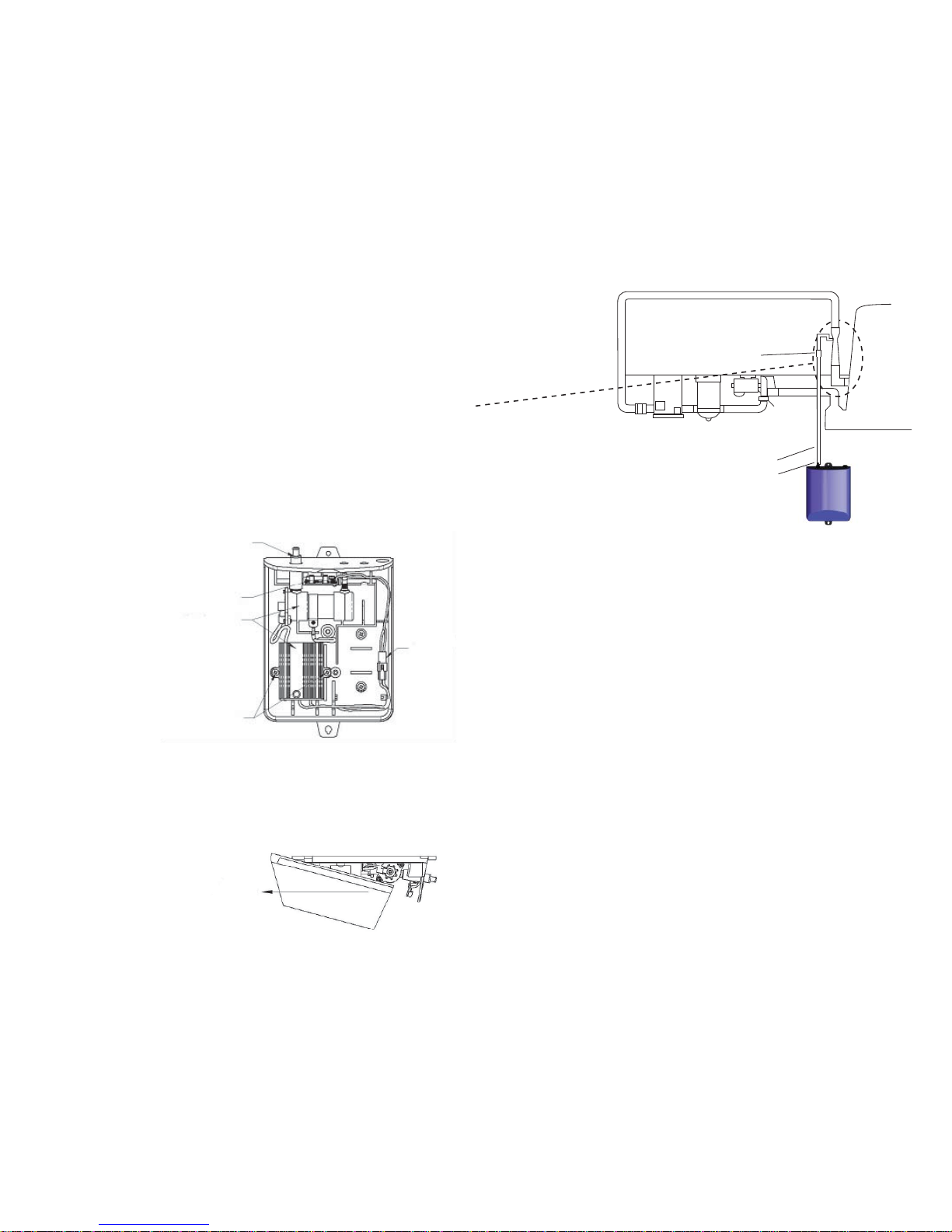
The EC-AG ozone generators described in this manual are designed to provide
the benefits of ozonated water in an environmentally safe and effective manner.
The high quality, specially engineered components ensure efficient ozone out-
put and reliable performance. As a result of proper use of the ozone generators,
unpleasant effects of traditional chemical use are virtually eliminated. The ozone
generators are safe and harmless to your equipment when installed properly.
1B Specifications
Flow rate:
15 scfh (nominal)
Flow rate and ozone output will vary with installation.
Power Requirements:
• EC-AG1: 120V, 60 Hz, 1Ø, 0.10 Amp
• EC-AG2: 120V, 60 Hz, 1Ø, 0.05 Amp
• EC-AG1-25: 230V, 50 Hz, 1Ø, 0.05 Amp
Shipping Weight:
• EC-AG1: Approx. 4.8 pounds / 2.2 kg
• EC-AG2: Approx. 4.8 pounds / 2.2 kg
• EC-AG1-25: Approx. 5.5 pounds / 2.5 kg
1C Warranty Summary
Limited Warranty:
1 year warranty on entire generator. See Warranty section for limitations and
details on obtaining warranty service.
Location Requirements:
Mounting: Wall mount in a clean, protected area.
Ambient Temp: 30°F - 120°F (0°C - 50°C)
4 EC-AGX Installation & Operation Manual 13
LIMITED ONE YEAR WARRANTY
The limited warranty set forth below applies to products manufactured by DEL
Ozone - and sold by DEL Ozone or its authorized dealers. This limited warranty is
given only to the first retail purchaser of such products and is not transferable to
any subsequent owners or purchasers of such products.
DEL Ozone warrants that it or its authorized dealers will repair or replace, at its
option, any part of such products proven to be defective in materials or work-
manship within ONE (1) year from the date of retail purchase of such products.
(All parts) ANY REPAIR OR REPLACEMENT WILL BE WARRANTED ONLY FOR
THE BALANCE OF THE ORIGINAL WARRANTY PERIOD. NOTE: USE ONLY DEL
Ozone AUTHORIZED REPLACEMENT PARTS. USE OF ANY OTHER PART(S) WILL
AUTOMATICALLY VOID THIS WARRANTY.
THIS LIMITED WARRANTY DOES NOT INCLUDE ANY OF THE FOLLOWING:
(a) any labor charges for troubleshooting, removal, or installation of such parts;
(b) any repair or replacement of such parts necessitated by faulty installation,
improper maintenance, improper operation, misuse, abuse, negligence, accident,
fire, repair materials, and/or unauthorized accessories; (c) any such products
installed without regard to required local codes and accepted trade practices;
(d) ANY IMPLIED WARRANTY OF MERCHANTABILITY OR IMPLIED WARRANTY
OF FITNESS FOR PARTICULAR PURPOSE, AND SUCH WARRANTIES ARE
HEREBY DISCLAIMED: AND (e) DEL Ozone SHALL NOT BE LIABLE UNDER ANY
CIRCUMSTANCES FOR LOSS OF USE OF SUCH PRODUCTS, LOST PROFITS,
DIRECT DAMAGES, INDIRECT DAMAGES, CONSEQUENTIAL DAMAGES AND/
OR INCIDENTAL DAMAGES.
TO OBTAIN WARRANTY SERVICE
Contact DEL Ozone: PO Box 4509, San Luis Obispo, CA 93401, 805.541.1601
When filing a claim, you must provide:
1. your name, mailing address and telephone number
2. the selling dealer’s name
3. proof of date of purchase
4. the date of failure
5. a description of the failure
11. Connect CD electrode to power supply connector.
12. Slide cover into position while lifting the base of the cover up.
13. Lower cover over CD electrode and snap cover tabs into place.
14. Replace cover Screw
15. Reinstall the EC-AGX into the original mounting location; reconnect ozone
supply tubing to hose barb and reconnect the power cord.
4D. Trouble Shooting
Knowledge of electrical applications is required for trouble shooting. Contact a
certified electrician if you are unsure of your ability to service the equipment. Im-
proper servicing will void the Warranty.
Symptom: No Flow.
1. Injector not supplying adequate suction.
a. Check pump and ensure water is flowing through injector.
b. Check that pump skimmer and filter are clean.
c. Check that injector is plumbed in the right direction.
d. Ensure that there is no debris clogged inside the injector.
2. Tubing is impaired.
a. Check for kinks or clogs.
b. Check for cracks or cuts.
c. Check connections.
d. Check that the check valve is installed with the arrow pointing towards
the injector.
e. Be sure that the check valve has not become fouled with debris.
Disconnect the ozone tubing from the injector. With the pump running,
test the end of the hose barb with your thumb, and feel for suction. Wash
your hands immediately afterwards to remove any residual nitric acid. If
there is sufficient suction without the check valve, replace the check valve
and tubing.
Symptom: Ozone tubing becomes yellow/brown and brittle.
1. The high concentration of ozone created by the corona discharge ozone
generators, as well as environmental conditions like UV sunlight will tend
to deteriorate the supplied ozone tubing. This is normal and acceptable,
as long as the tubing doesn’t become cracked and leak. Because of this,
DEL recommends replacing the ozone supply tubing and your check valve
every year.
12 EC-AGX Installation & Operation Manual
SECTION 2 Installation
2A Location
The ozone generator units are designed for wall mounting. See Figure 1. Mount
generator in a clean, protected area, either indoors or outdoors (preferably out of
direct sunlight). Locate generator out of reach of sprinklers or drainage spouts.
Allow sufficient access for maintenance and all tubing and electrical wires. Ozone
generator should be installed at least (not less than) one foot above the maximum
water level. See Section 2D-2, Ozone Gas Line, for plumbing instructions based
on mounting location.
2B Wall Mounting
1. Refer to Figure 1 to mark the locations for the two mounting screws.
2. Install screws (or other hardware appropriate for mounting surface) through
the two mounting holes built in to the base of the EC-AG ozone system.
Figure 1 Wall Mount
2C Electrical
2C-1. Main Power: Connect the ozone generator to the pool timing clock so that
the ozone generator operates simultaneously with the pool pump. The circuit must
be protected by a ground-fault circuit interrupter (GFCI) installed in accordance to
electrical code. Refer to the IMPORTANT SAFETY INSTRUCTIONS at the beginning
of this manual for important wiring information.
If the EC-AG power cord comes with a built-in receptacle and the pump is equipped
with a standard plug (NEMA 5-15P), the pump may be plugged in on top of the EC-
AG cord (pump current must not exceed 15A). Plug must be protected from mois-
ture.
5
2D Plumbing
Ozone gas is introduced to the pool circulation line using a venturi injector.
Suction developed by the venturi allows the ozone generator to operate safely
under vacuum.
Note: The injector needs to be installed after all other equipment or possible
failure may occur.
2D-1. Plumbing the Above Ground Injector Assembly
1. Wrap Teflon tape on all male pipe threads.
2. Disconnect the pool’s return hose from the pool at the point where the tubing
returns into the pool. Keep the hose elevated to prevent pool from draining through
pump and filter.
3. Screw 1-1/2˝ nipple loosely into 1-1/2˝ elbow, then screw this assembly
into the pool’s 1-1/2˝ eye ball fitting stopping when tight and elbow is pointed
down (Figure 2).
4. Screw the Venturi Injector into the elbow. NOTE: Make sure the injector
is installed with the flow arrow pointed in the direction of water flow and with the
Ozone port accessible.
5. Connect the pool’s return hose to the bottom (inlet) of the injector using
1-1/2” flex hose barb and the stainless steel hose clamp.
6. Attach Hose Barb Fitting to Ozone Port on Injector (See Figure 2a or
Figure 2b).
CD Ozone System
Figure 2 Installation Schematic for Injector Assembly
6
Check Valve
EC-AG
Ozone
Generator
Ozone Out Fitting
Ozone Supply Tubing
Pump
Filter Heater
EC-AGX Installation & Operation Manual 11
Figure 5 Sliding cover off
4. Slide the cover forward and off.
4C-3. Ozone Module Replacement
1. Open the ozone generator as described in section 4C-2.
Figure 6 Internal component locations
2. Remove the power supply mounting screws.
3. Disconnect power supply connector (red & black wires).
4. Lift CD electrode up and out of hose barb insert (o-ring and hose barb
insert may remain attached to electrode).
5. Carefully pull circuit board vertically out of base slot & remove old fuse.
6. Insert new fuse and carefully push circuit board back into base seat.
7. Insert new hose barb insert making sure to align the hose barb correctly
and insert it completely into its slotted hole.
8. Install power supply and mounting screws. Route power supply wires
through pegs.
9. Place new o-ring onto CD electrode outlet (reference old electrode location).
10. Install CD electrode by inserting into hose barb and gently pushing intocradle.
Slide Cover Off
Power
Supply
Connector
Power Supply
Mounting Screws
Power Supply & CD
Electrode Assembly
Fuse
(On Circuit Board)
Hose Barb Insert
Lift Cover Up
4C Generator Servicing
4C-1. The ozone generator must be removed from the wall before servicing. To
remove the ozone generator:
1. Disconnect service to ozone generator.
2. Disconnect the power cord from the pool timer circuit.
3. Disconnect the ozone supply tubing from the bottom end cap of the
ozone generator.
4. Remove the two wall mounting screws.
4C-2. Opening the ozone generator
The ozone generator enclosure consists of two plastic parts that clip together.
They are held in place by one screw. To open the enclosure:
1. Remove the cover screw on the back side of the base of the EC-AGX (Figure 3).
Figure 3 Cover screw and tabs
2. Using a flat head screwdriver or fingers, pry the two cover tabs outward
to release the cover from the base.
Figure 4 Lifting Cover
3. Lift the cover up (Figure 4).
10
Cover Screw
Cover Tabs
EC-AGX Installation & Operation Manual 7
Venturi Injector
1-1/2˝ Nipple
Ozone Port
(Unplugged)
1-1/2˝ Elbow
Hose Barb
Fitting
Pool Return
Hose
Stainless Steel
Hose Clamp
2D-2. Ozone Gas Line
Connect the end of the Ozone Supply Tubing that is closest to the Check Valve
to the Hose Barb Fitting on the Injector. Secure with a supplied hose clamp.
If the generator is mounted above the water line attach the other end of the
Ozone Supply Tubing to the ozone out fitting on the EC-AG and secure with
the supplied hose clamps.
If the generator is mounted below the water line, the ozone supply tubing
must be run to a point above the water line. Simply coil the tubing into a
complete circle about 6˝ diameter and fasten it above the water line. This will
act as a water trap to prevent water from running back to the generator.
Venturi Injector
Ozone Port
(Unplugged)
Hose Barb
Fitting
Pool Return
Hose
Stainless Steel
Hose Clamp
1-1/2˝ Nipple
1-1/2˝ Elbow
Figure 2a
Injector Assembly
Exploded View
Figure 2b
Mazzei Injector Assembly
Exploded View
SECTION 3 Operation
3A General
To achieve optimal performance from the ozone system, the pool must be as clean
as possible to start with.
1. Backwash or clean filters one day before starting the ozone generator.
2. Superchlorinate pool water using a chlorine based shock treatment.
3. Test pool chemistry and adjust pH between 7.4 and 7.6. Adjust total
alkalinity between 80 and 120 ppm.
4. Run pool filtration continuously for 24 hours prior to starting ozone system.
3B Initial System Start-Up
1. Turn on pool circulation system.
2. Check for leaks.
3. Verify that ozone is being pulled into the injector by checking for bubbles
at the return.
If you experience complications, see TROUBLE SHOOTING Section 4D, call
800.676.1335 or visit www.delozone.com for assistance.
3C System Shut-Down
If the system is to be shut down for an extended period disconnect the ozone gen-
erator power cord and disconnect the Ozone Gas Line from the ozone generator.
SECTION 4 Maintenance and Service
4A System Electromechanical Overview
4A-1. Internal Components: Ozone Module: Each ozone module consists of a
power supply connected by two high voltage wires to an electrode.
8 EC-AGX Installation & Operation Manual 9
4B System Maintenance
4B-1. Ordering Information
To locate a dealer nearest you call 1.800.676.1335 ext. 249 or visit our web site
www.delozone.com
Be prepared with the following information:
• Name • Address • Model # • Date Purchased
4B-2. Standard Replacement Parts List
1. EC-AG1 & EC-AG1-25 Ozone Module 5-1308-01
2. EC-AG2 Ozone Module 5-1307-01
3. Module Parts Kit 9-0566
4. Ozone Check Valve and Tubing Assembly 9-0777-01
Item 4 must be replaced once each year.
4B-3. Ozone module performance will degrade over time. Replace the ozone
module after 15,000 hours of operation. (15,000 hours equals approximately 5
years for a pool system that operates 8 hours/day, every day.) See Section 4C for
module replacement instructions.
4B-4. While operating, check regularly to see if bubbles are entering the pool.
(If you have installed an MDV, check the MDV for bubbles.)
4B-5. Regularly inspect ozone supply tubing for cracks or wear. Also check to
make sure no water is present between the Check Valve and the Ozone Genera-
tor. This indicates Check Valve failure. Replace the Ozone Check Valve and Tub-
ing Assembly (replacement part number 9-0777-01) immediately**.
**WARNING: Trace amounts of nitric acid may be present in the check valve
or tubing and could be mildly corrosive. If condensation is present, shut off
ozone generator and allow the moisture to be drawn out or dried up prior to
servicing.

This manual suits for next models

2

Popular Oxygen Equipment manuals by other brands

Drive DeVilbiss Healthcare 1060AW Service manual

Drive DeVilbiss Healthcare

Drive DeVilbiss Healthcare 1060AW Service manual

Precision Medical EasyPulse POC PM4150 Series user manual

Precision Medical

Precision Medical EasyPulse POC PM4150 Series user manual

Invacare Platinum Mobile POC1-100 Series Service manual

Invacare

Invacare Platinum Mobile POC1-100 Series Service manual

C-Aire FreeStyle manual

C-Aire

C-Aire FreeStyle manual

Halma Crowcon CellarSafe Installation and operating instructions

Halma

Halma Crowcon CellarSafe Installation and operating instructions

Aulisa Guardian Angel GA1000 Series Instructions for use

Aulisa

Aulisa Guardian Angel GA1000 Series Instructions for use

Drive Bonsai OM-812 PRODUCT INFORMATION AND INSTRUCTIONS

Drive

Drive Bonsai OM-812 PRODUCT INFORMATION AND INSTRUCTIONS

Aanderaa 4330 operating manual

Aanderaa

Aanderaa 4330 operating manual

Maxtec MAXO2+A operating instructions

Maxtec

Maxtec MAXO2+A operating instructions

C-Aire FreeStyle Comfort Technical manual

C-Aire

C-Aire FreeStyle Comfort Technical manual

Maxtec MaxVenturi Maintenance manual

Maxtec

Maxtec MaxVenturi Maintenance manual

ResMed Mirage Quattro user guide

ResMed

ResMed Mirage Quattro user guide

OGSI OG-15 Installation, operation and maintenance manual

OGSI

OGSI OG-15 Installation, operation and maintenance manual

Maxtec MaxO2ME Instructions for use

Maxtec

Maxtec MaxO2ME Instructions for use

Inogen One G3 user manual

Inogen

Inogen One G3 user manual

AirSep Focus Portable Patient manual

AirSep

AirSep Focus Portable Patient manual

manuals.online logo
manuals.online logoBrands
  • About & Mission
  • Contact us
  • Privacy Policy
  • Terms and Conditions

Copyright 2025 Manuals.Online. All Rights Reserved.