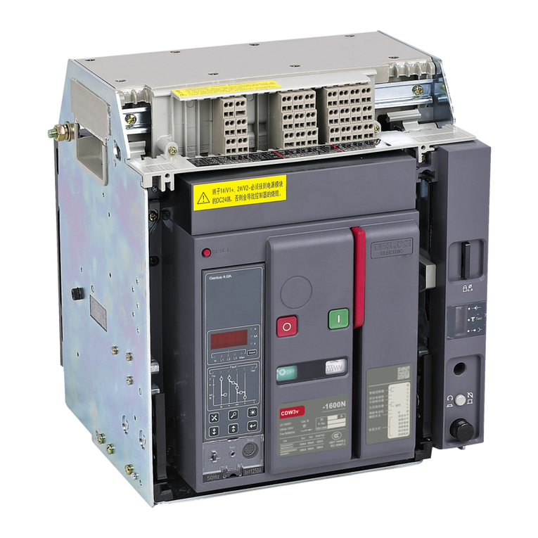
Delixi NAVIGATOR Series User manual

CDM3S Series
MOULDED-CASE CIRCUIT-
BREAKER
NAVIGATOR
Series
User Manual
Standards: GB/T 14048.2 IEC 60947-2
□Before the installation and use of this product, please
carefullyread this manual and keep it properlyfor reference.

-1-
Safety Notice
Please carefully read this manual before the installation, operation, service, maintenance and inspection of this
product, and install and operate this product properly in accordance with the instructions.
Danger:
●Do not operate the circuit breaker with wet hands;
●Do not touch the conductive part during operation;
●Power off the product before maintenance and repair;
●Do not test the product with a short-circuit way;
Attention:
●The installation, maintenance and repair shall be conducted by a qualified professional;
●All features of product have been set before shipment, and they cannot be removed or adjusted without
permission during operation;
●Before use, check that the rated voltage, rated current, frequency and features conform to the working
requirements;
●To prevent interphase short circuit, a phase partition is provided with the product. Please install this partition
properly before use, and the bare wire or copper bus of the wiring terminal shall be insulated to ensure safe
insulation;
●To test the insulation resistance or power frequency withstand voltage, first disconnect the electronic
components between the current loops, otherwise the product will be damaged;
●If found damage or heard abnormal sound when unpacking product, please stop use and contact the supplier;
●As the overload alarm non-trip product has no overload protection function, it is only suitable for overload
alarm non-trip site;
●Before powering on the product with a under-voltage release, apply the rated voltage onto the under-voltage
release;
●Please use all matching accessories provided by our company to ensure quality. Our company will not be
responsible for any adverse consequence due to the use of accessories not provided by our company;
●Please dispose the scrapped product waste properly. Thanks for your cooperation.
Test:
●As the overload alarm non-trip product has no overload protection function, it is only suitable for overload
alarm non-trip site;
●1000VDC megameter is used;
●The insulation resistance shall not be less than 20MΩ;

-2-
Between the contacts of circuit breaker, between the phases, and between the phase and the housing (the
housing is covered with metal foil);
Connected to the under-voltage release located between the incoming inlet and the circuit breaker housing
of main circuit;
Note: If no megameter is used by user, a power frequency withstand voltage tester can be used instead it for
testing. The measuring parts refer to the insulation test method, and the voltage 2000V shall be applied for 5
seconds.
Please note the part marked with
1. About CDM3S
1.1 Packing list
Product
mode
CDM3S-
Mounting
screws - Qty.
Wiring screws
- Qty.
(3P/4P)
Interphase
partition - Qty.
(3P/4P)
Extended
handle
Circuit
breaker
Manual (with
certificates)
63/100 C
M4×55-4
M6×16-6/8
4/6
-
1
1
125b S/F
M4×40-4
M8×16-6/8
4/6
-
1
1
160/250 S
M4×55-4
M8×20-6/8
4/6
-
1
1
160/250 F/N
M4×75-4
M8×20-6/8
4/6
-
1
1
400 F/N
M5×85-4
M10×25-6/8
4/6
-
1
1
630 F
M5×85-4
M10×35-6/8
4/6
1
1
1
630b F/N
M5×85-4
M12×30-6/8
4/6
1
1
1
800 F/N
M6×95-4
M12×35-6/8
4/6
1
1
1
1600 F/N
M5×75-4
M10×40-12
(800A-1250A)
M10×45-12
(1600A)
4(3P)
1
1
1
1.2 Product working environment and conditions
The product grade of this product is IP30 (IP00 for wiring terminal)
The pollution class of this product is Level 3
The rated working voltage is 400/415V, 500V, 690V
The altitude of the installation location shall not exceed 2000m. If the altitude exceeds 2000m, please contact
the manufacturer
The allowable ambient temperature is ranged -25℃to +70℃and the relative humidity (at the ambient
temperature 25℃) is ≤95%; the mean temperature within 24h does not exceed 35℃.
(Note: If used within the temperature range -25℃to -5℃and +40℃to +70℃, please contact the
manufacturer)

-3-
2. Operation and debugging CDM3S
Turn the handle of circuit breaker to the “Trip” position before shipment
Turn the operating handle to the “OFF” position before trip
Turn the circuit breaker to the “ON” position
With the Trip button pressed, the handle of circuit breaker shall return to the “Trip” position
3. Outline, installation, and wiring dimensions of CDM3S series
X-X: as the central axis of base, the same below
Y-Y: as the central axis of handle, the same below Insert here on the upper cover in the arrow
direction marked on the flash barrier
ON
Trip
OFF

-4-
CDM3S-1600 wiring dimensions

-5-
Unit: mm
Product
model
CDM3S
-
Num
ber
of
poles
Outline dimensions
Installation dimensions
4. Install CDM3S
4.1 Safety distance of circuit breaker Unit: mm
Product model CDM3S-
Amin
Bmin
Cmin
Dmin
63/100 C
60
30
25
12.5
125b S/F
60
30
10
0
160/250 S/F/N
85
42.5
10
0
400 F/N
110
55
10
0
630F, 630b F/N
110
55
10
0
800 F/N
110
55
10
0
1600 F/N
110
55
10
0

-6-
Conductive material
Distance from the
non-conductive
material
Attention:
1. When the circuit breakers are installed in parallel, an insulation distance between the terminals shall be kept.
A long terminal cover or an extra phase partition is recommended between two products for insulation
protection;
2. If a more contact installation is required, a zeroarcing cover is recommendedto obtaina smaller safetydistance;
3. Please note the insulation protection of the mounting base to prevent that the ground clearance of the busbar,
terminal or screw is less than 8mm. It is recommended that the base plate attached on the long terminal cover
is installed or an additional ground insulation protection is provided.
4.2 Size of hole on the circuit breaker panel Unit: mm
Product
model
CDM3S-
Number
of poles
Exposed front cover and toggle handle
Exposed toggle handle
L1
L11
W11
W1
L2
L21
W2
63/100 C
3P
86
43
39
78
53
20
27
4P
103
125b S/F
3P
99
49.5
47.5
95
56
25
31
4P
125
160/250
S/F/N
3P
105
52.5
55
110
56
30.5
31
4P
145
400 F/N
3P
153
76.5
76.5
153
85
42.5
56
4P
201
630 F
3P
153
76.5
76.5
153
85
42.5
56
4P
201
630b F/N
3P
153
70.5
92.5
185
85
36.5
56
4P
243
800 F/N
3P
138
69
106.5
213
85
42.5
56
4P
283
1600 F/N
3P
148
53.5
106.5
213
118
38.5
84

-7-
Inlet terminal
Inlet terminal
Outlet terminal
Outlet terminal
Exposed front cover and toggle handle Exposed toggle handle
4.3 Size of hole on the mounting plate
Unit: mm
Product model
CDM3S-
Number of
poles
A
A1
B
C
Ø D
63/100 C
3P
111
55.5
25
-
5
4P
25
125b S/F
3P
129
64.5
30
-
5
4P
30
160/250 S/F/N
3P
126
63
35
-
5
4P
35
400 F/N
3P
215
107.5
44
-
6.5
4P
-
630 F
3P
215
107.5
44
-
6.5
4P
-
630 b F/N
3P
200
94
58
-
6.5
4P
-
800 F/N
3P
243
121.5
70
-
7.5
4P
70
1600 F/N
3P
378
189
70
-
6.2

-8-
4.4 Recommended values of wiring capacity
Rated current
(A)
10
16
20
25
32
40
50
63
80
100
125
140
160
180
200
225
250
315
350
400
Recommended
sectional area
of wire (mm2)
1.5
2.5
4
6
10
16
25
35
50
70
95
120
185
240
Rated current (A)
500
630
700
800
1000
1250
1600
Recommended sectional area of wire
(mm2)
150×2
185×2
240×2
-
-
-
Recommended sectional area of
copper bus (mm2)
150×2
200×2
250×2
300×2
400×2
500×2
Attention:
Please note the sizes C, C1 and C2 among the outline, installation and wiring dimensions of CDM3S series and the
diameter of the corresponding wiring screw; select an appropriate wiring terminal or busbar to satisfy the
corresponding wiring capacity requirements.

-9-
4.5 Recommended values of the wiring screw tightening torque
Product model
CDM3S-
63/100
C
125b
S/F
160/250
S/F/N
400 F/N
630 F
630b
F/N
800 F/N
1600
F/N
Socket hex wiring
screw
M6
M8
M8
M10
M10
M12
M12
M10
Torque (N.m)
5-7
7-10
7-10
11-14
11-14
15-19
15-19
11-14
Attention:
1. Please tighten the wiring screws of product according to the recommended torque, because too large or too
small tightening torque will cause poor contact or damage to the housing.
2. As 63/100C product is designed with a back-panel wiring plug to realize the back-panel wiring function, please
tighten or loosen the wiring screws on the mounting bracket or flat plate, otherwise the plugs and screws will
be ejected out.
4.6 Recommended self-drill and self-tap mounting screw (self-drill and self-tap mounting screw with cross
recessed countersunk head GB/T15856.2)
Product model CDM3S-
63/100 C
125b S/F
160/250 S
160/250 F/N
Model and spec. of
recommended self-drill and
self-tap screw
ST4.2X60
ST4.2X42
ST4.2X60
ST4.2X70
(Without self-
lock slot)
Attention:
Some models of this product can be installed with self-drill and self-tap screws. Only common screws and nuts are
provided when delivery, and specific self-drill and self-tap screws shall be purchased by users.
5. Internal accessories and expansion function
5.1 Internal accessories (under-voltage release, shunt release, assist, alarm, dual-assist, and assist)
Assembly diagram
Right accessory cavity
2 Install accessories Accessory line
3 Sort the lead wires
Left accessory cavity
1 Remove the cover 4 Close the cover
Tighten the screws

-10-
Mountable accessories in all cavities
Left accessory cavity: Left shunt, left under-voltage, left single assist, left dual assist, left alarm, and left assist larm
Right accessory cavity: right shunt, right single assist, right dual assist, right alarm, and right assist alarm
Note: 1600 product’s left accessory cavity accommodates left shunt, and left under-voltage releases; the right
accessory cavity accommodates right single assist, right dual assist, right alarm, and right assist alarm.
Wiring and schematic diagram
Under-voltage release Shunt release Alarm contact Single assist/dual assist contact Assist alarm contact
Electrical parameters
Product model
CDM3S-
Under-voltage coil holding power (W)
Min. Power of suction of under-voltage coil (W)
AC440V
AC230V
AC400V
AC230V
63/100
0.94
0.94
Auxiliary suction type
Auxiliary suction type
125b
0.44
0.44
Auxiliary suction type
Auxiliary suction type
250
0.6
0.6
Auxiliary suction type
Auxiliary suction type
400/630/800
0.77
0.75
225
190
1600
1.12
1.08
Auxiliary suction type
Auxiliary suction type
Product model
CDM3S-
Mounting position
Min. action power of shunt coil (W)
AC400V
AC230V
DC24
63/100
Right and left
cavities
155
150
96
125b
Right and left
cavities
120
75
115
250
Left cavity
135
165
109
Right cavity
85
75
90
400/630/800
Right and left
cavities
101
60
98
1600
Left cavity
175
130
80

-11-
Electrical parameters of alarm and assist
Resistive current
3A
Use category (GB/T 14048.5-1)
AC15
DC13
Working voltage 50/60Hz
AC400V
0.3A
-
DC220V
-
0.15A
Test requirements for internal accessories
1) Under-voltage release:
1.1) Under 35% ~ 70% rated working voltage, the under-voltage release can work to trip the circuit breaker;
1.2) Under 85% ~ 110% rated working voltage, the under-voltage release can work to power on the circuit
breaker reliably;
1.3) When the rated working voltage is below 35%, the under-voltage release can work to prevent powering
on circuit breaker;
2) When the shunt release is applied with 70%~110% rated voltage, the circuit breaker can be disconnected
reliably, and the handle is at the Trip position;
3) For circuit breaker with an auxiliary contact, the breaker can be closed and open normally and the conversion
signal of auxiliary contact shall be normal;
4) For circuit breaker with an alarm contact, the breaker shall be closed and tripped (with the red trip button
pressed), and the conversion signal of alarm contact shall be normal.
Attention:
1. When the rated power voltage of shunt release is DC24V, the maximum length of copper wire cannot exceed
the value listed in table below:
Rated control power voltage Us
(DC24V)
Sectional area 1.5mm2
Sectional area 2.5mm2
100% Us
150m
250m
80% Us
100m
160m

-12-
2. If the requirements of the above table cannot be satisfied, it is recommended that the shunt release control
circuit is designed according to the following figure:
Power input
3. The continuous power-on time of shunt release shall not exceed 5s, otherwise the shunt release will be burnt
out. When the selected rated control power voltage is DC24V, the rated current of control loop shall reach 4.5A
~ 5.5A.
4. The under-voltage release is of the backpack structure when delivery, and all other accessories are of the lead-
wire structure by default.
5. The default wire length for product of the lead-wire structure is about 500mm. If a longer lead length required
by user cannot drive the shunt or under-voltage release, the relay mode recommended in “Note 2” is used to
satisfy minimum drive power.
5.2 Overload alarm non-trip
Wiring diagram
Principle: The product uses one group of normally-open contacts. In case of overload fault of any phase in product,
the product will issue an alarm signal within a certain delay time. RB11 / RB14 means the wire code.
Electrical parameters
Overload alarm non-trip
Rated working voltage
Working current
AC250V
0.5A
DC30V
0.5A

-13-
Attention:
1. The product without this function has no overload protection.
2. After the overload fault disappears, the product will be kept in the alarm state within some time due to thermal
effect.
3. The product has a lead-wire structure by default, and the default wire length is about 220mm.
6. Maintenance and service
Maintenance and service must be conducted by qualified professionals.
The product shall be de-energized.
The product shall be maintained and serviced once every year under the normal operating conditions, and the
maintenance items see Table below
Item
Contents
Appearance
No dust, no condensate; clean if found; the housing is not damaged
Wiring terminal connection
Tighten it according to the torque listed in the 4.5 Recommended values of the
wiring screw tightening torque to prevent looseness
Handle ON / OFF / Trip
operation
The handle shall be operated flexibly without blockage; this product uses a self-
clean contact structure. If found any change of the contact resistance due to
oxidization, please conduct multiple ON / OFF actions to realize the stripping of
oxidization layer between mobile and static silver points reducing the contact
resistance.
7. Unpacking inspection
After unpacking, please check the product for damage, check the exposed metal for rust, and check the product for
all defects due to poor transportation or storage. If found the above phenomenon, do not stop operating this product,
and contact the supplier in time.

-14-
8. Company’s commitment
Under the premise that users follow the use and storageconditions and the product are wellsealed, within 36 months
from the production date, our company will provide repair and replacement service free of charge for any damage
or abnormal use due to poor manufacture quality. A paid repair will be provided if the warranty period expires. For
any damage due to one of the following situations, a paid repair will be given even if within the warranty period:
Improper operation, maintenance, or storage;
Modified and improper repair without permission;
Damage due to falling off or during installation after purchase;
Force majeure such as earthquakes, fires, lightning strikes, abnormal voltages, and secondary disasters;
If you have any question, please contact our company’s customer service department.
Customer service hotline: 400-826-8008

Certificate
Name: Moulded-case circuit-breaker
Model: CDM3S
This product passes the inspection and is allowed
to be shipped.
Executive standard: GB/T 14048.2
Inspector: Check 01
Production date: See the label of the inner box
For more information, please
subscribe the WeChat official
account
Address: Delixi High-Tech Industrial Park, Liushi Town, Leqing City, Zhejiang Zip: 325604
Tel: (86-577) 6177 8888
Fax: (86-577) 6177 8000
Customer service hotline: 400-826-8008
www.delixi-electric.com
This User Manual was issued in Nov., 2021 First Version
Other manuals for NAVIGATOR Series
4
This manual suits for next models
1
Table of contents
Other Delixi Circuit Breaker manuals
