manuals.online logo
Brands
  1. Home
  2. •
  3. Brands
  4. •
  5. GE
  6. •
  7. Circuit Breaker
  8. •
  9. GE Power Break II User manual

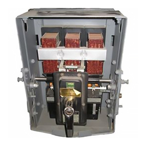
GE Power Break II User manual

Jg
,
.
.
.
.
.
.
ySXZMEJjJS
"
gm
i
;
L
^
EZi
^
T
-
'
zzzjl
{
/
i
-
~
-
Power
Break
®
/
/
Circuit
Breaker
Accessories
Mechanical
interlock
for
Draw
-
Out
Breakers
,
2500
-
4000
A
Frames
Introduction
The
Mechanical
Interlock
accessory
,
catalog
number
SPDOWB
40
and
shown
in
Figure
1
,
can
be
installed
in
2500
-
4000
ampere
frame
Power
Break
®
II
draw
-
out
circuit
breakers
.
This
accessory
is
for
use
only
with
circuit
breakers
,
draw
-
out
substructures
,
and
shutters
with
a
manufacture
date
code
later
than
E
640
=
(
where
E
represents
the
plant
where
manufactured
,
6
is
the
year
,
40
is
the
week
of
that
year
,
and
=
is
the
decade
code
—
in
this
case
,
the
90
s
)
.
When
two
breakers
in
adjacent
compartments
are
connected
with
an
interlock
rod
,
as
shown
in
Figure
2
,
this
accessory
prevents
the
simultaneous
closing
of
both
breakers
.
When
either
breaker
is
ON
,
the
other
-
will
immediately
trip
if
an
attempt
is
made
to
turn
it
ON
also
.
When
both
breakers
are
OFF
,
either
breaker
may
be
turned
ON
.
However
,
when
one
breaker
is
ON
,
an
attempt
to
close
the
second
breaker
causes
its
closing
springs
to
discharge
without
moving
the
contact
arms
.
An
override
feature
is
provided
in
case
of
a
race
condi
-
tion
(
both
breakers
turned
ON
simultaneously
)
,
so
that
the
breaker
designated
as
primary
turns
ON
and
the
secondary
breaker
trips
.
Either
or
both
circuit
breakers
may
be
CHARGED
at
any
time
,
but
the
interlock
operation
activates
only
when
one
of
the
breakers
is
ON
.
&
Figure
2
.
Mechanical
Interlock
attached
to
Power
Break
II
draw
-
out
circuit
breakers
.
Horizontal
or
Vertical
Connection
The
interlocked
breakers
can
be
mounted
and
con
-
nected
either
vertically
(
one
breaker
above
the
other
)
or
horizontally
(
breakers
mounted
side
by
side
)
.
The
connecting
rod
can
be
installed
in
either
of
two
posi
-
tions
for
the
desired
action
.
All
end
connectors
are
provided
,
so
the
customer
need
only
supply
a
14
-
20
threaded
rod
of
the
appropriate
length
.
Installation
WARNING
:
Before
installing
any
accessories
,
turn
the
breaker
off
,
disconnect
it
from
all
voltage
sources
,
and
discharge
the
charging
springs
.
AVERTISSEMENT
:
Avant
d
’
installer
tout
accessoire
,
mettre
le
disjoncteur
en
position
OFF
,
le
deconnecter
de
toute
tension
d
’
alimentation
,
et
decharger
les
ressorts
d
’
armement
.
EPW
r
/
r
*
o
,
O
'
If
shutters
have
been
installed
in
the
draw
-
out
substruc
-
ture
,
they
must
be
removed
before
the
mechanical
interlock
can
be
installed
.
Reinstall
the
shutters
after
completing
installation
of
the
interlock
.
Figure
1
.
Mechanical
Interlock
accessory
components
.
Courtesy of NationalSwitchgear.com
Breaker
Unit
The
primary
breaker
unit
has
a
solid
operating
and
the
secondary
breaker
unit
has
a
spring
-
loaded
override
link
.
In
the
event
of
a
race
condition
,
in
which
both
breakers
are
turned
ON
simultaneously
while
both
are
OFF
,
the
primary
unit
turns
ON
and
the
secondary
unit
trips
.
Either
the
primary
or
secon
-
dary
breaker
may
be
installed
in
the
top
or
right
com
-
partment
.
Use
the
following
procedure
to
install
the
interlock
units
on
each
circuit
breaker
.
1
.
Remove
the
knockout
on
the
rear
of
the
breaker
,
as
shown
in
Figure
3
.
Be
sure
to
clean
the
edges
of
the
hole
,
so
that
the
interlock
plunger
can
move
freely
in
and
out
.
2
.
Install
the
interlock
in
step
1
,
as
shown
in
Figure
4
.
3
.
Install
the
interlock
mechanism
,
as
shown
in
Figure
5
,
so
that
the
roller
goes
into
the
slot
in
the
trip
claw
.
Secure
with
four
#
10
-
32
Philips
-
head
screws
tightened
to
15
in
-
lb
.
4
.
Check
that
the
fork
on
the
interlock
mechanism
moves
freely
.
Rotating
it
counterclockwise
should
actuate
the
trip
plunger
.
Closing
the
breaker
should
move
it
clockwise
,
while
tripping
the
breaker
should
return
it
to
the
center
position
.
link
Figure
5
.
Interlock
mechanism
installed
on
the
breaker
.
plunger
in
the
hole
made
Substructure
unit
and
Interconnection
Use
the
following
procedure
to
install
the
interconnect
components
into
the
draw
-
out
substructures
and
to
connect
the
breakers
.
The
type
A
unit
has
a
link
attached
to
the
bottom
tee
connection
,
while
the
type
B
unit
has
the
curved
link
attached
to
the
top
tee
connec
-
tion
.
The
two
units
thus
operate
in
opposite
directions
to
provide
the
interlock
function
.
The
type
A
unit
must
be
installed
in
the
top
compart
-
ment
for
a
vertical
installation
or
in
the
left
compart
-
ment
for
a
horizontal
installation
.
This
provides
a
“
pull
”
operation
so
that
the
rod
connecting
the
com
-
partments
does
not
buckle
.
After
performing
steps
1
and
2
,
which
are
identical
for
both
vertical
and
horizontal
connections
,
go
to
the
appropriate
step
3
to
continue
the
installation
1
.
Remove
the
screw
at
the
rear
of
the
substructure
indicated
in
Figure
6
.
h
=
ZS
?
-
y
.
yf
Figure
3
.
Knockout
removed
for
installation
of
the
interlock
plunger
.
figure
6
Screw
that
must
be
removed
to
provide
clearance
for
the
substructure
interlock
mechanism
2
.
Install
the
units
to
the
breaker
mounting
sup
-
ports
as
shown
in
Figure
7
.
Attach
with
four
Philips
-
head
#
10
-
32
in
each
compart
-
screws
ment
,
tightened
to
15
in
-
lb
.
If
the
breakers
are
mounted
one
above
the
other
(
vertical
connec
-
Figure
4
.
Interlock
plunger
installed
in
the
breaker
.
Courtesy of NationalSwitchgear.com
Horizontal
Interconnection
3
.
For
a
horizontal
installation
,
attach
the
long
rod
ends
to
the
pins
on
the
pivots
as
shown
in
Fig
-
ure
9
.
A
variety
of
connecting
hardware
is
pro
-
vided
in
the
Mechanical
Interlock
kit
;
the
i
/
4
-
20
threaded
rod
is
supplied
by
the
customer
.
4
.
Slip
the
provided
heat
-
shrink
tubing
over
the
rod
so
that
it
provides
insulation
within
the
compartment
through
which
the
rod
passes
(
right
-
side
unit
)
.
Shrink
the
tubing
in
place
with
a
hot
air
source
of
100
—
300
°
C
(
212
—
572
°
F
)
.
5
.
Adjust
the
length
of
the
rod
so
that
the
pivot
-
to
-
pivot
distance
is
equal
to
the
center
-
to
-
center
dis
-
tance
between
the
two
compartments
.
Figure
7
.
Installation
of
a
compartment
unit
onto
the
breaker
mounting
support
.
Rod
Extender
tion
)
,
the
type
A
unit
must
be
installed
in
the
upper
compartment
and
the
type
B
in
the
lower
.
If
the
breakers
are
mounted
side
by
side
(
horizontal
connection
)
,
the
type
A
unit
must
be
installed
in
the
right
compartment
and
the
type
B
in
the
left
.
C
-
Rod
Connector
"
B
"
Unit
Attach
to
Lower
Long
Rod
End
Pivot
Point
on
Vertical
Interconnection
3
.
For
a
vertical
installation
,
attach
the
rod
ends
to
the
pivots
as
shown
in
Figure
8
.
The
rod
ends
are
provided
in
the
Mechanical
Interlock
kit
;
the
i
/
4
-
20
threaded
rod
is
supplied
by
the
cus
-
tomer
.
4
.
Adjust
the
length
of
the
rod
so
that
the
pivot
-
to
-
pivot
distance
is
equal
to
the
distance
between
the
two
compartments
.
Both
Units
Lock
Nut
Figure
9
.
Attachment
of
the
interconnection
rod
to
the
compartment
units
for
a
horizontal
installation
..
The
view
is
from
the
rear
of
the
compartment
Lower
Link
Installation
Testing
1
/
,
"
A
"
Unit
Before
installing
the
breakers
,
verify
that
the
rod
linkage
is
centered
and
free
to
move
in
either
direc
-
tion
.
After
installing
the
breakers
in
the
compartments
,
charge
the
closing
springs
on
both
breakers
.
Close
one
of
the
breakers
,
then
attempt
to
close
the
other
.
The
second
breaker
should
immediately
trip
.
Repeat
the
test
with
the
breakers
in
the
opposite
order
.
If
the
sec
-
ond
breaker
does
not
trip
in
either
case
,
check
that
the
rod
connecting
the
breakers
is
free
to
move
i
n
both
directions
when
the
breakers
are
sequenced
from
OFF
to
ON
.
If
the
rod
is
adjusted
too
short
,
one
of
the
breakers
will
nuisance
trip
even
when
the
other
breaker
is
off
.
If
the
rod
is
adjusted
too
long
,
the
inter
-
lock
mechanism
will
not
operate
properly
.
A
good
length
is
one
that
eliminates
the
slack
between
the
compartment
linkages
.
Washer
and
Cotter
Pin
Lock
Nut
Rod
End
Jpper
Link
Figure
8
Attachment
of
the
interconnection
rod
to
the
compartment
units
for
a
vertical
installation
.
The
view
is
from
the
rear
of
the
compartment
.
Courtesy of NationalSwitchgear.com
Tro
ub
/
e
-
Shoo
ting
The
following
guide
is
provided
for
trouble
-
shooting
and
isolating
common
problems
.
It
does
not
cover
every
possible
situation
.
Contact
the
ED
&
C
Customer
Support
Center
at
800
-
843
-
3742
if
any
problem
is
not
resolved
by
these
procedures
.
Corrective
Action
Possible
Cause
Symptom
The
rack
is
not
fully
inserted
Check
the
rack
position
and
,
if
necessary
,
fully
seat
in
the
substructure
.
The
second
breaker
is
turned
Normal
operation
.
The
first
breaker
is
prevented
from
closing
when
the
second
breaker
is
already
ON
.
The
circuit
breaker
will
not
close
and
trips
when
an
attempt
is
made
to
turn
it
ON
.
1
.
the
breaker
.
ON
.
Check
the
length
of
the
connecting
rod
and
verify
compartments
is
adjusted
too
that
it
is
adjusted
to
the
exact
distance
between
the
breakers
.
If
the
condition
persists
,
lengthen
the
rod
adjustment
.
The
rod
that
links
the
two
short
.
Verify
that
the
rod
linkage
is
centered
and
free
to
move
in
either
direction
when
both
circuit
break
-
ers
are
turned
OFF
.
The
interlock
unit
is
not
cor
-
rectly
installed
.
Verify
that
the
breaker
plunger
is
installed
and
that
the
knockout
was
removed
without
ragged
burrs
that
would
prevent
the
plunger
from
sliding
in
and
out
of
the
breaker
when
it
is
turned
ON
and
OFF
.
The
fork
should
move
from
left
to
right
when
the
breaker
is
turned
ON
.
The
interlock
was
improp
-
erly
installed
or
the
plunger
was
not
installed
.
Both
circuit
breakers
can
be
turned
ON
at
the
same
time
.
2
.
Verify
that
the
rod
linkage
is
centered
and
free
to
move
in
either
direction
when
both
circuit
break
-
ers
are
turned
OFF
.
The
rod
connecting
the
two
breakers
is
not
free
to
move
.
Check
the
length
of
the
connecting
rod
and
verify
that
it
is
adjusted
to
the
exact
distance
between
the
breakers
.
If
the
condition
persists
,
shorten
the
rod
adjustment
.
The
rod
connecting
the
two
breakers
is
adjusted
too
long
.
The
type
A
and
B
devices
are
reversed
,
so
that
the
inter
-
Reverse
the
installation
of
the
A
and
B
units
on
the
circuit
breakers
.
Vertical
interlock
:
A
unit
on
top
and
B
unit
on
bottom
;
horizontal
interlock
:
A
unit
on
right
and
B
unit
on
left
.
3
.
The
rod
connecting
the
breaker
compart
-
ments
bends
or
buckles
lock
is
operating
in
a
“
push
”
when
either
breaker
rather
than
a
“
pull
”
mode
.
is
turned
ON
.
These
instructions
do
not
cover
all
details
or
variations
in
equipment
nor
do
they
provide
for
every
possi
-
ble
contingency
that
may
be
met
in
connection
with
installation
,
operation
,
or
maintenance
.
Should
further
information
be
desired
or
should
particular
problems
arise
that
are
not
covered
sufficiently
for
the
purchaser
’
s
purposes
,
the
matter
should
be
referred
to
the
GE
Company
.
GE
Electrical
Distribution
&
Control
General
Electric
Company
41
Woodford
Ave
.
,
Plainville
,
CT
06062
©
1996
General
Electric
Company
DEH
-
012
0596
Courtesy of NationalSwitchgear.com

Other manuals for Power Break II

8

Other GE Circuit Breaker manuals

GE EntelliGuard GBKRKR User manual

GE

GE EntelliGuard GBKRKR User manual

GE WavePro 3200 A User manual

GE

GE WavePro 3200 A User manual

GE GL 311 F3/4031 P/VE User manual

GE

GE GL 311 F3/4031 P/VE User manual

GE A Series Pro-Stock THQB User manual

GE

GE A Series Pro-Stock THQB User manual

GE POWER BREAK MICRO-VERSATRIP E39ME20 User manual

GE

GE POWER BREAK MICRO-VERSATRIP E39ME20 User manual

GE A Series Pro-Stock TQD User manual

GE

GE A Series Pro-Stock TQD User manual

GE GEH-62808 User manual

GE

GE GEH-62808 User manual

GE Spectra Series AMC3FGB User manual

GE

GE Spectra Series AMC3FGB User manual

GE EntelliGuard G User manual

GE

GE EntelliGuard G User manual

GE AK-2-15 User manual

GE

GE AK-2-15 User manual

GE ML-14-0 User manual

GE

GE ML-14-0 User manual

GE Shunt Trip User manual

GE

GE Shunt Trip User manual

GE S2500 User manual

GE

GE S2500 User manual

GE SPRCS024 User manual

GE

GE SPRCS024 User manual

GE EntelliGuard AKR30S-800A User manual

GE

GE EntelliGuard AKR30S-800A User manual

GE FK800 User manual

GE

GE FK800 User manual

GE ReliaGear Pro-Stock Spectra RMS User manual

GE

GE ReliaGear Pro-Stock Spectra RMS User manual

GE FE 160 User manual

GE

GE FE 160 User manual

GE AM-13.8-750-4C User manual

GE

GE AM-13.8-750-4C User manual
GE MicroVersaTrip AK-50 User manual

GE

GE MicroVersaTrip AK-50 User manual

GE MicroVersaTrip AKR-75 User manual

GE

GE MicroVersaTrip AKR-75 User manual

GE MicroVersaTrip Plus Series User manual

GE

GE MicroVersaTrip Plus Series User manual

GE Spectra Series AMC6FGB User manual

GE

GE Spectra Series AMC6FGB User manual

GE M-PACT User manual

GE

GE M-PACT User manual

Popular Circuit Breaker manuals by other brands

NHP Terasaki TemBreak PRO P SE Series user manual

NHP

NHP Terasaki TemBreak PRO P SE Series user manual

Eaton C Series Instruction leaflet

Eaton

Eaton C Series Instruction leaflet

Siemens 3VT9300-4WN00 operating instructions

Siemens

Siemens 3VT9300-4WN00 operating instructions

Siemens SIRIUS 3RA2933-2AA1 operating instructions

Siemens

Siemens SIRIUS 3RA2933-2AA1 operating instructions

Allen-Bradley 140G-K-CEAA Installation

Allen-Bradley

Allen-Bradley 140G-K-CEAA Installation

ABB SACE Emax 2 manual

ABB

ABB SACE Emax 2 manual

Siemens PCTL83 installation instructions

Siemens

Siemens PCTL83 installation instructions

C&S Electronics WiNmaster 2 manual

C&S Electronics

C&S Electronics WiNmaster 2 manual

Siemens 3AH37 operating instructions

Siemens

Siemens 3AH37 operating instructions

Doepke DRCBO 2 Series User information

Doepke

Doepke DRCBO 2 Series User information

Siemens 3WN6 operating instructions

Siemens

Siemens 3WN6 operating instructions

Siemens 3VT9500-8LC10 operating instructions

Siemens

Siemens 3VT9500-8LC10 operating instructions

Siemens TC1J6600 installation instructions

Siemens

Siemens TC1J6600 installation instructions

Puls DIMENSION PISA-B-8CL2-B1 quick start guide

Puls

Puls DIMENSION PISA-B-8CL2-B1 quick start guide

WEG UBW400 user manual

WEG

WEG UBW400 user manual

Doepke DFS 4 A EV Installation and operating manual

Doepke

Doepke DFS 4 A EV Installation and operating manual

Westinghouse DH instructions

Westinghouse

Westinghouse DH instructions

CHINT RT28 Mounting instructions

CHINT

CHINT RT28 Mounting instructions

manuals.online logo
manuals.online logoBrands
  • About & Mission
  • Contact us
  • Privacy Policy
  • Terms and Conditions

Copyright 2025 Manuals.Online. All Rights Reserved.