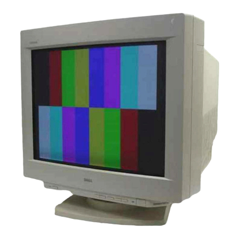
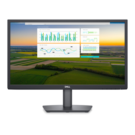
Dell E152FPc User manual

DELL E152FPc
1
15” LCD MONITOR
DELL E152FPc
THESE DOCUMENTS ARE FOR REPAIR SERVICE INFORMATION ONLY. EVERY REASONABLE EFFORT
HAS BEEN MADE TO ENSURE THE ACCURACY OF THIS MANUAL; WE CANNOT GUARANTEE THE
ACCURACY OF THIS INFORMATION AFTER THE DATE OF PUBLICATION AND DISCLAIMS RE LIABILITY
FOR CHANGES, ERRORS OR OMISSIONS.
MANUFACTURE DATA: MAR.-20-2005
SERVICE MANUAL

DELL E152FPc
2
Table of Contents
TABLE OF CONTENTS...............................................................................................................2
1. MONITOR SPECIFICATIONS .................................................................................................4
2. LCD MONITOR DESCRIPTION ..............................................................................................5
3. OPERATING INSTRUCTIONS................................................................................................6
3.1 GENERAL INSTRUCTIONS...............................................................................................6
3.2 CONTROL BUTTONS........................................................................................................6
3.3 ADJUSTING THE PICTURE...............................................................................................7
4. INPUT/OUTPUT SPECIFICATION........................................................................................10
4.1 INPUT SIGNAL CONNECTOR.........................................................................................10
4.2 FACTORY PRESET DISPLAY MODES............................................................................10
4.3 POWER SUPPLY REQUIREMENTS ...............................................................................11
4.4 PANEL SPECIFICATION..................................................................................................11
5. BLOCK DIAGRAM................................................................................................................14
5.1 MONITOR EXPLODED VIEW..........................................................................................14
5.2 SOFTWARE FLOW CHART.............................................................................................15
5.3 ELECTRICAL BLOCK DIAGRAM.....................................................................................17
6. SCHEMATIC..........................................................................................................................18
6.1 MAIN BOARD...................................................................................................................18
6.2 PWPC BOARD.................................................................................................................22
7. PCB LAYOUT........................................................................................................................25
7.1 MAIN BOARD...................................................................................................................25
7.2 PWPC BOARD.................................................................................................................27
7.3 KEYPAD BOARD .............................................................................................................28
8. MAINTAINABILITY................................................................................................................28
8.1 EQUIPMENTS AND TOOLS REQUIREMENT.................................................................28
8.2 TROUBLE SHOOTING ....................................................................................................29
9.WHITE-BALANCE, LUMINANCE ADJUSTMENT.................................................................35
10. EDIT CONTENT...................................................................................................................36
11. BILL OF MATERIAL LIST ...................................................................................................37
12.DEFINITION OF PIXEL DEFECTS.......................................................................................53

DELL E152FPc
3
Revision List
Revision Date Revision History TPV model
A00 Mar-20-2005 Initial Release
A01 April-25-2006
Add” Max Brightness measurement” on
Page36

DELL E152FPc
4
1. MONITOR SPECIFICATIONS
Driving system TFT Color LCD
Size 38.1mm(15.0")
Pixel pitch 0.297mm(H) x 0.297mm(V)
Viewable angle 120˚(H) 100˚(V)
Flat Panel
Response time (typ.) 25 ms
Video Analog Only
Sync. Type H/V TTL Separate and Composite Sync.
H-Frequency 30kHz – 63kHz
Input
V-Frequency 56-76Hz
Display Colors Over 16.2 million Colors
Dot Clock 80MHz
Max. Resolution 1024 x 768
Plug & Play VESA DDC2BTM
ON Mode
<25W
<35W(For Samsung XH panel)
Power Consumption OFF Mode
<1W
Maximum Screen Size Horizontal : 11.9”(304.1mm)
Vertical:8.9”(228.1mm)
Power Source 110~240VAC,50~60Hz
Environmental
Considerations
Operating Temp: 5°C to35°C
Storage Temp.:-20°C to80°C
Packaged 5.31Kgs Unit
Weight (N. W.) Unpackaged 3.50Kgs Unit

DELL E152FPc
5
2. LCD MONITOR DESCRIPTION
The LCD MONITOR will contain a main board, an internal PWPC board, keypad board, which house the flat panel
control logic, brightness control logic and DDC.The internal PWPC board will drive the backlight of panel and the
DC-DC conversion. and provides the 5V DC-power to main board.
Monitor Block Diagram
Video signal, DDC
PWPC board
(Include adapter and Inverte
r
board)
Flat Panel and
CCFL backlight
Main Board
Keyboard
RS232 Connector
For white balance
adjustment in factory
mode
CCFL Drive.
AC-IN
100-240V
Host Computer

DELL E152FPc
6
3. OPERATING INSTRUCTIONS
3.1 GENERAL INSTRUCTIONS
Press the power button to turn the monitor on or off. The other control buttons are located at front panel of the
monitor. By changing these settings, the picture can be adjusted to your personal preferences.
-The power cord should be connected.
-Connect the video cable from the monitor to the video card.
-Press the power button to turn on the monitor, the power indicator will light up.
3.2 CONTROL BUTTONS
-Power Button:
When pressed, the monitor enters the off mode, and the LED turns blank. Press again to restore normal status.
-Brightness Button:
The Brightness Button is used to select the Brightness/Contrast adjust functions. Press to switch functions or
adjust settings.
-Auto Adjust Key:
The Auto Adjust Key is used to automatically set the H Position, V Position, Clock and Phase.
-Power Indicator:
Green — Power On mode.
Orange — Power Saving mode.
Blank —Power Off Mode.
A.Buttons for the OSD menu (On-Screen-display)
B. Brightness/Contrast menu Button
C. Auto Adjust Button
D. Power On/Off Button and indicator
Control Buttons

DELL E152FPc
7
3.3 ADJUSTING THE PICTURE
To set the OSD menu, perform the following steps:
Briefly press the SELCT / MENU button to activate the OSD menu.
The main menu appears on the screen with icons for the setting functions.
The first symbol (Exit) is highlighted.
Necessary, press the- or + button to mark another icon (e.g. Positioning).
Press the SELECT/MENU button to select the highlighted icon.
The corresponding setting window (here: Positioning) is displayed.
The first symbol (Exit) is highlighted.
If necessary, press the – or + button to mark the desired icon.
Press the SELECT/MENU button to select the highlighted function.
Press the – or + button to adjust the value for the selected function.
Press the SELECT/MENU button to exit the function.
Press the SELECT/MENU button to exit the sub-menu when “Exit” function is highlighted;
All changes are stored automatically.

DELL E152FPc
8
Adjusting the brightness and contrast
Calling the Brightness / Contrast setting window using Brightness button.
Brightness
Setting the brightness of the display
With this function you change the brightness of the background lighting.
Contrast
Setting the contrast of the display
With this function you modify the contrast of bright colour tones.
Adjusting size and position
Calling the Positioning setting window
H-Position Adjusting the horizontal position
With this function you move the picture to the left or to the right.
V-Position Adjusting the vertical position
With this function you move the picture up or down.
Setting Image
Calling the Image setting window
Auto Adjust Auto adjust will produce best image automatically, The information of “Auto Adjust In
Progress” will show;
Pixel clock Adjusting the pixel clock
Phase Adjusting the phase
Setting colour temperature and colours
Calling the Color setting window
Selecting the colour temperature
The colour temperature is measured in K (= Kelvin). You can select from Normal Preset,
Blue Preset, Red Preset to User Preset;
Normal preset
Blue preset
Red preset
User preset
= Original colour of the LCD display, it’s 6500K;
=5700Kcolour of the LCD display, it’s 9300K;
=9300K colour of the LCD display, it’s 5700K;
= Setting user-defined colours
In the user preset setting you can change the colour ratios of the basic colours (red,
green, blue) as required.
Setting display of the OSD menu
Calling the OSD Set up setting window
Horizontal
Position
Setting the horizontal position of the OSD menu
With this function you move the OSD menu to the left or to the right.

DELL E152FPc
9
Vertical
Position
Setting the vertical position of the OSD menu
With this function you move the OSD menu up or down.
OSD
Hold Time
Setting the display duration of the OSD menu, the default value is 20s;
With this function you select a value from 0 to 60 seconds.
If the set time expires without a setting being made, the OSD menu is automatically faded
out.
OSD
Lock
Setting the display of the OSD menu lock or unlock.
With this function you select Yes to lock OSD, NO to unlock it.
Setting Language
Calling the Language setting window
With this function you choose between English (default setting), French, German,
Spanish and Japanese as the language for the OSD menu.
Factory Reset
Activating the factory settings
With this function all settings except Language of OSD are reset to the factory settings
without prompting for confirmation.

DELL E152FPc
10
4. INPUT/OUTPUT SPECIFICATION
4.1 INPUT SIGNAL CONNECTOR
15-pin D-sub connector
PIN NO. DESCRIPTION PI N NO. DESCRIPTION
1. Red 9. +5V
2. Green 10. Detect Cable
3. Blue 11. Ground
4. Ground 12. DDC-Serial Data
5. Ground 13. H-Sync
6. R-Ground 14. V-Sync
7. G-Ground 15. DDC-Serial Clock
8. B-Ground
VGA Connector layout
15
610
11 15
4.2 FACTORY PRESET DISPLAY MODES
Display Mode
Horizontal
Frequency (kHz)
Vertical
Frequency (Hz)
Pixel Clock
(MHz)
Sync Polarity
(Horizontal /
Vertical)
DOS 720 x 400 31.5 70.1 28.3 -/+
VGA 640 x 480 31.5 60.0 25.18 -/-
VESA 640 x
480
37.5 75.0 31.5 -/-
VESA 800 x 600 37.9 60.3 40.0 +/+
VESA 800 x 600 46.9 75.0 49.5 +/+
VESA 1024 x 768 48.4 60.0 65.0 -/-
VESA 1024 x 768 60.0 75.0 78.8 +/+
For ergonomic reasons, a screen resolution of 1024 x 768 pixels is recommended. Because of the technology used
(active matrix) an LCD monitor provides a totally flicker-free picture even with a refresh rate of 60 Hz.

DELL E152FPc
11
4.3 POWER SUPPLY REQUIREMENTS
4.3.1 INPUT REQUIREMENTS
AC INPUT VOLTAGE: 100V ~ 240V
AC INPUT FREQUENCY: 50 ~ 60 HZ
AC INPUT CURRENT: 1.5A MAX
INRUSH CURRENT: 50AMAX AT 220V
LEAKAGE CURRENT: 3.5 mAMax.
4.3.2 OUTPUT REQUIREMENTS
ITEM MIN. TYP. MAX. UNIT REMARK
Output voltage (12V) 11.4 12 12.6 V
Output current (12V) 0 1.5 2.0 A
Output voltage ( 5V) 4.75 5.0 5.25 V
Output current (5V) 0 1.5 2.0 A
Ripple & Noise (12V) 200 mV
Ripple & Noise (5V) 100 mV
4.4 PANEL SPECIFICATION
4.4.1 PANEL FEATURE
4.4.2 DISPLAY CHARACTERISTICS

DELL E152FPc
12
4.4.3 OPTICAL CHARACTERISTICS

DELL E152FPc
13
4.4.4 PARAMETER GUIDE LINE FOR CCFL INVERTER
BACKLIGHT

DELL E152FPc
14
5. BLOCK DIAGRAM
5.1 MONITOR EXPLODED VIEW

DELL E152FPc
15
5.2 SOFTWARE FLOW CHART
1
2
N
Y
5
Y
N
10
Y
N
12
Y
N
7
Y
N
6
4
3
8
9
14
11
13
Y
N
15
Y
N16
17
19
Y
N
18

DELL E152FPc
16
1) MCU Initializes.
2) Is the EEprom blank?
3) Program the EEprom by default values.
4) Get the PWM value of brightness from EEprom.
5) Is the power key pressed?
6) Clear all global flags.
7) Are the AUTO and SELECT keys pressed?
8) Enter factory mode.
9) Save the power key status into EEprom.
Turn on the LED and set it to green color.
Scalar initializes.
10) In standby mode?
11) Update the lifetime of back light.
12) Check the analog port, are there any signals coming?
13) Does the scalar send out an interrupt request?
14) Wake up the scalar.
15) Are there any signals coming from analog port?
16) Display "No connection Check Signal Cable" message. And go into standby mode after the message
disappears.
17) Program the scalar to be able to show the coming mode.
18) Process the OSD display.
19) Read the keyboard. Is the power key pressed?

DELL E152FPc
17
5.3 ELECTRICAL BLOCK DIAGRAM
Main Board
OSD
Control
Interface
(CN301)
Scalar GmZan3
(Include MCU, ADC, OSD)
(U200)
MCU
MTV312MV
(U202)
EEPROM
M24C16
(U201)
D-Sub
Connector
(CN100)
EEPROM
24C02
(U100)
H-sync, V-sync R/G/B
DB12_SDA,
DB15_SCL
EPR_SDA
EPR_SCL
LCD Interface
(CN201)
LVDS Signal output
12MHz Crystal
(X200)
TCLK/XTAL

DELL E152FPc
18
6. SCHEMATIC
6.1 MAIN BOARD
GND
VGA_5V
R117
100 1/16W
GND
Q102
2N7002E
GND
BIN
R107
75 1/16W
R111
100 1/16W
BLUE-
C108 0.01uF
R120
100 1/16W
ZD102
LL5232B 5.6V 5%
TXD
R101
100 1/16W
FB101 0 1/16W
GREEN+
R129
0 1/16W
R102
75 1/16W
Analog Input
H
ZAN3 LCD Control Board
AOC
14
星期五
,
十月
03, 2003
Title
Size Document Number Rev
Date: Sheet of
VS-IN
C103 0.01uF
ZD105
LL5232B 5.6V 5%
C109 NC
UART_DI
SHEET2
SOG_MCSS
+5V
D101
BAV99
ZD106
LL5232B 5.6V 5%//NC
R128
NC
GND
GREEN+
GND
FB102 0 1/16W
GND
GND
+5V
R106
100 1/16W
HSYNC
R103
100 1/16W
R115
100 1/16W
C111 0.01uF
VSYNC
R131
NC
R105
47K 1/16W
C104
0.1uF/16V
R118 100 1/16W
R108
100 1/16W
FB100 0 1/16W
DDC_SCL_A1
RXD
R125
0 1/16W
R109 47 1/16W
R133
0 1/16W
BLUE-
GND
RXD UART_DO
SHEET2
RED-
GND
GND
DDC_SDA_A1
R124
0 1/16W
R127
0 1/16W
GND
GND
RED-
D103
BAV99
GND
R132
0 1/16W
C100 0.01uF
CN100
VGA
1
6
2
7
3
8
4
9
5
11
12
13
14
15 10
1716
R110 47 1/16W
R113
100 1/16W
R104
47K 1/16W
U100
M24C02WMN6
4
81
2
37
6
5
GND
VCCA0
A1
A2 WP
SCL
SDA
GIN
DDC_SDA_A1
ZD107
LL5232B 5.6V 5%//NC ZD100
LL5232B 5.6V 5%
D102
BAV99
R126
NC
ZD101
LL5232B 5.6V 5%
RED+
R122
2.2K 1/16W
Pins 6/7/8 are R/G/B
return lines resp.
RED+
VGA_5V
VGA_PG
TXD
R114
4.7K 1/16W
BLUE+
GND
BLUE+
R119
100 1/16W
GND
C106
NC
R123
NC
GND
DDC_SCL_A1
GND
VSYNC
GND
GND
DDC_SCL P.2
HSYNC
R116 NC
DDC_5V
ZD104
LL5232B 5.6V 5%
R121
2.2K 1/16W
DDC_SDA P.2
DDC_SCL_A1
C107 0.01uF
C105 0.01uF
C101
0.1uF/16V
Q101
2N7002E
ZD103
LL5232B 5.6V 5%
HS-IN
R100 NC
R130
NC
R112
75 1/16W
+5V
DDC_SDA_A1
C102
NC
D100
BAT54C
3
1
2
GREEN-
75-ohm terminating
resistor very close to
the VGA conn.
GND
+5V
RIN
1. TO SUPPORT SOG -->ADD R123 1M OHM

DELL E152FPc
19
BLUE-
GND
EXTERNAL OSC.
TX0-O
R224
NC
HCLK/ALE
GND
3.3V_AVDD
RDn
MEM_REG
R220 4.7K 1/16W
KEY_MANU
C206
0.1uF/16V
+5V
RST#
R225 100 1/16W
PANEL_EN
R206 100 1/16W
LOW
+
C216
22uF/16V
OSC_SEL (HDATA2)
+5V
R210 100 1/16W
DDC_SCL
C234
NC
+
C219
10uF/16V
1.8V_AVDD
GND
C224
0.1uF/16V
TX1-O
C205
0.1uF/16V
LOW
RED-
R2314.7K 1/16W
NC
PANEL_PWR
+
C210
22uF/16V
KEY_ON/OFF
C212
0.1uF/16V
3.3V_DVDD
GND
VGA_PG
R201
NC
HDATA1
+5V
R2294.7K 1/16W
HS-IN
BKLT_EN
FB203
120 OHM
X200
12MHz
GND
R213 4.7K 1/16W
+5V
ZAN3
H
ZAN3 LCD Control Board
AOC
24
星期五
,
十月
03, 2003
Title
Size Document Number Rev
Date: Sheet of
BLUE+
C211
0.1uF/16V
LED-GRN
TX1+O
C202
0.1uF/16V
R212 4.7K 1/16W
R205 100 1/16W
R235 NC
GND
GND
R216 NC
KEY_LEFT
KEY_ON/OFF
RP200 100 1/16W
1
2
3
4
8
7
6
5
Reserved
3.3V_AVDD
C229
0.1uF/16V
RED+
DDC_SCL
TX0+O
R202
0 1/16W
R200
NC
GND
R208 100 1/16W
HIGH
DDC_SDA
RDn
R236 NC
+3.3V
R219
10K 1/16W
+
C225
22uF/16V
MEM_REG
R222
NC
Close to respective power Pins
BLON/OFF
GND
TX3-O
R209 NC
R221 4.7K 1/16W
U200
GMZAN3-L
GMZAN3-L
97
98
93
94
88
89
110
111
78
83
84
122
123
19
125
126
127
128
124
118
1
116
3
104
106
95
99
90
102
22
41
75
109
35
20
81
74
77
85
86
21
23
36
42
62
76
82
103
101
4
18
5
15
14
13
12
11
8
7
6
16
17
9
10
50
107
87
91
96
100
61
115 114
63
60
59
58
57
56
55
54
53
52
113
92
79
73
72
71
70
47
46
45
44
43
40
39
37
34
33
30
29
28
27
26
25
24
51
48
49
112
117
121
80
32
31
2
105
108
119
120
38
64
65
66
67
68
69
RED+
RED-
GREEN+
GREEN-
BLUE+
BLUE-
XTAL
TCLK
GPIO2
STI_TM1
STI_TM2
GPIO6/AD6
GPIO7/AD5
AVDD_3.3
HDATA3/AD3
HDATA2/AD2/OSC_SEL
HDATA1/AD1/HP1
HDATA0/AD0/HP0
HFS/AD4
HCLK/ALE
RESETn
GPIO3/IRQn
VCO_LV
VDD_ADC_1.8
VDD_RPLL_1.8
AGND_GREEN
AGND_RED
AGND_BLUE
AGND_ADC
RVDD_3.3
RVDD_3.3
RVDD_3.3
AVDD_RPLL_3.3
CVDD_1.8
CVDD_1.8
CVDD_1.8
PPWR
PBIAS
HSYNC
VSYNC
CRVSS
CRVSS
CRVSS
CRVSS
CRVSS
CRVSS
CRVSS
GND_ADC
ADC_TEST
AVDD_3.3
AVSS
AVSS
CH0N_LV
CH0P_LV
CH1N_LV
CH1P_LV
CH2N_LV
CHKP_LV
CH3N_LV
CH3P_LV
AVSS
AVDD_3.3
CHKN_LV
CH2P_LV
CRVSS
VBUFS_RPLL
AVDD_BLUE_3.3
AVDD_GREEN_3.3
AVDD_RED_3.3
AVDD_ADC_3.3
RVDD_3.3
CRVSS CVDD_1.8
GPIO9
GPIO8
RESERVED
RESERVED
RESERVED
RESERVED
RESERVED
RESERVED
GPIO11
GPIO10
CRVSS
SOG_MCSS
GPIO1/PWM1
DCLK
DVS
DHS
DEN
RESERVED
RESERVED
RESERVED
RESERVED
GPIO13
GPIO12
RESERVED
RESERVED
RESERVED
RESERVED
RESERVED
RESERVED
RESERVED
RESERVED
RESERVED
RESERVED
RESERVED
RESERVED
RESERVED
CVDD_1.8
RVDD_3.3
GPIO4/MEM_REG
GPIO5/AD7
GPIO0/PWM0
RESERVED
RESERVED
RESET_OUT
VSS_RPLL
AVSS_RPLL
WRn
RDn
RESERVED
RESERVED
RESERVED
RESERVED
RESERVED
RESERVED
RESERVED
+5V
C209
0.1uF/16V
KEY_RIGHT
R203 4.7K 1/16W
C233
22 ohm 1/16w
G-PROBE
1.8V_DVDD
LOW
VS-IN
R217
0 1/16W
R207 100 1/16W
HIGH
GND
DDC_SDA
PANEL_EN
FB202
120 OHM
GND
R214 4.7K 1/16W
RP201 100 1/16W
1
2
3
4
8
7
6
5
BKLT_EN
CN201
PITCH 2.0mm
2
4
6
8
10
12
14
16
18
20
1
3
5
7
9
11
13
15
17
19+3.3V TX3+O
C230
22pF
C0603
GREEN-
KEY_RIGHT
GND
C213
0.1uF/16V
KEY_AUTO
HIGH
8/22 del C218 for DIP
GND
GND
R227
NC
UART_DO
1.8V_DVDD
TX2+O
R218
10K 1/16W
MUTE
R211
NC
XTAL and INTERNAL OSC
HIGH
GND
R232 4.7K 1/16W
LED-GREEN
BKLT_PWM
C231
22pF
C0603
HIGH
+1.8V
C215
0.1uF/16V
SOG_MCSS
WRn
TX2-O
GND
U202
MTV312MV
2
3
4
5
6
7
8
9
10
11
13
14
15
16
17
18
19
20
21
22
24
25
26
27
28
29
30
31
32
33
35
36
37
38
39
40
41
42
43
44
1
12
23
34
DA1/P5.1
DA0/P5.0
VDD3
HSDA2/P7.6
HSCL2/P7.5
RST
VDD
P6.3/AD3
VSS
X2
ISDA/P3.4/T0
ISCL/P3.5/T1
STOUT/P4.2
P6.2/AD2/HLFH1
P1.0
P1.1
P3.2/INT0
P1.2
P1.3
P1.4
P1.6
P1.7
P6.1/AD1
P6.0/AD0
HSDA/P3.1/TXD
HSCL/P3.0/RXD
P6.4/DA10
P6.5/DA11
P6.6/DA12
P6.7/DA13
DA7/HCLAMP
VBLANK/P4.0
HBLANK/P4.1
DA9/P7.2
DA8/P7.1
DA5/P5.5
DA4/P5.4
DA3/P5.3
HSYNC/P7.3
VSYNC/P7.4
DA2/P5.2
X1
P1.5
DA6/P5.6/CKO
FB200
120 OHM
BOOTSTRAP OPTIONS
C228
0.1uF/16V
LOW
3.3V_AVDD
C223
0.1uF/16V
HDATA0
KEY_AUTO
TXCK-O
C200
0.1uF/16V
U201
M24C16-MN6T
1
2
3
4
8
7
6
5
A0
A1
A2
GND
VCC
TEST
SCL
SDA
LED-ORG
C222
0.1uF/16V
1.8V_AVDD
HS-IN
C214
0.1uF/16V
GND
R228
NC
N/A
BKLT_PWM
WP
C220
0.1uF/16V
C217
0.1uF/16V
3.3V_DVDD
GND
FB201
120 OHM
KEY_MANU +5V
C226
0.1uF/16V
C208
0.1uF/16V
When X2 is used to drive ZAN3 (the optional X1 crystal is not used)
remove the shunt from JP1.
GREEN+
R223
100 1/16W
6-wire Genesis I/F
GND
R226 100 1/16W
LOW
C204
0.1uF/16V
WP
C221
0.1uF/16V
GND
3.3V_DVDD
R204 4.7K 1/16W
UART_DI
RST#
+
C201
10uF/16V
STBY
2-wire I/F
C207
0.1uF/16V
+5V
R233 4.7K 1/16W
VS-IN
LED-ORANGE
KEY_LEFT
TXCK+O
CN200
1
2
3
4
R2304.7K 1/16W
GND
TCLK
C203
0.1uF/16V

DELL E152FPc
20
R311 4.7K 1/16W
POWER
C302
0.1uF/16V
PANEL_EN
CP300
0.001uF
81
72
63
54
KEY_RIGHT
Q303
PMBS3904
32
1
PANEL_PWR
GND
S
2
ENTER
G
3
+5V
keyboard&panel power
H
ZAN3 LCD Control Board
AOC
34
星期五
,
十月
03, 2003
Title
Size Document Number Rev
Date: Sheet of
+5V
LEFT
GND
AO3401
D
R306
10K 1/16W
GND
LCD_+3.3V
RP300 100 1/16W
1
2
3
4
8
7
6
5
GRNLED
KEY_ON/OFF
LED-GREEN
CP301
0.001uF
81
72
63
54
KEY_MANU
R307
10K 1/16W
Q302
PMBS3904
32
1
GND
GND
Q301
PMBS3904
32
1
Q300
AO3401
R304 100 1/16W
R301 4.7K 1/16W
1
KEY_LEFT
LED-ORANGE
1
+5V
ORGLED
CN301
1
2
3
4
5
6
7
8
C300
0.1uF/16V
2
R310 4.7K 1/16W
RP301
4.7K 1/16W
1
2
3
4
8
7
6
5
3
KEY_AUTO
R308
1K 1/16W
RIGHT
+
C301
22uF/16V
AUTO
Table of contents
Other Dell Monitor manuals

Dell
Dell E2016 User manual

Dell
Dell S2240T User manual

Dell
Dell E1913S User manual

Dell
Dell UltraSharp 1704FPV User instructions

Dell
Dell UltraSharp U3421WE User manual

Dell
Dell U2410 - UltraSharp - 24" LCD Monitor User manual

Dell
Dell U2410 - UltraSharp - 24" LCD Monitor User manual

Dell
Dell S3221QSA User manual

Dell
Dell D7523QTc User manual

Dell
Dell IN2020M User manual