Dell MR2217 User manual

Dell MR2217 Medical Display
User’s Guide
Model: MR2217
Regulatory model: MR2217b

Warnings, Cautions, and Notes
WARNING: A WARNING indicates a potential for property damage, personal
injury, or death.
CAUTION: A CAUTION indicates potential damage to hardware or loss of data if
instructions are not followed.
NOTE: ANOTE indicates important information that helps you make better use
of your computer.
This product is protected by U.S. and international copyright and intellectual property laws.
Dell™ and the Dell logo are trademarks of Dell Inc. in the United States and/or other
jurisdictions. All other marks and names mentioned herein may be trademarks of their
respective companies.

Contents | 3
Contents
1 Safety Information . . . . . . . . . . . . . . . . . . . . . . . . . .5
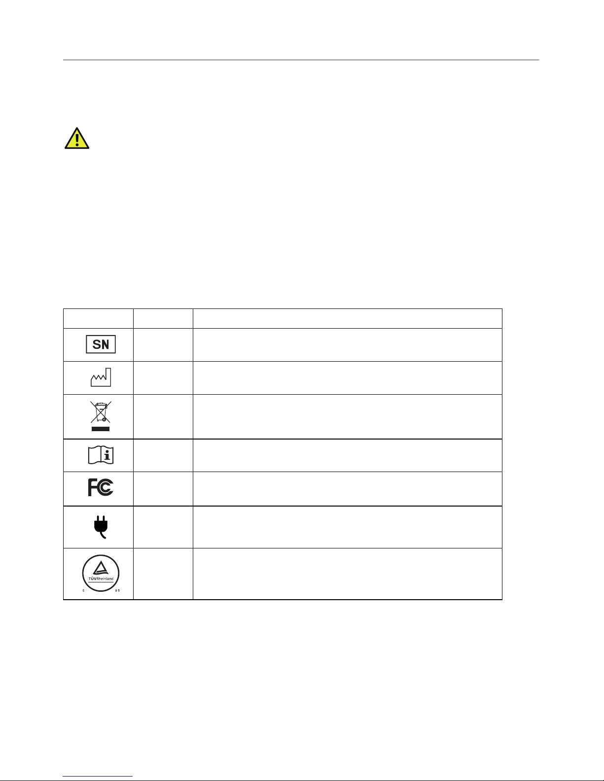
Symbols on the Device. . . . . . . . . . . . . . . . . . . . . . . . . . . . 5
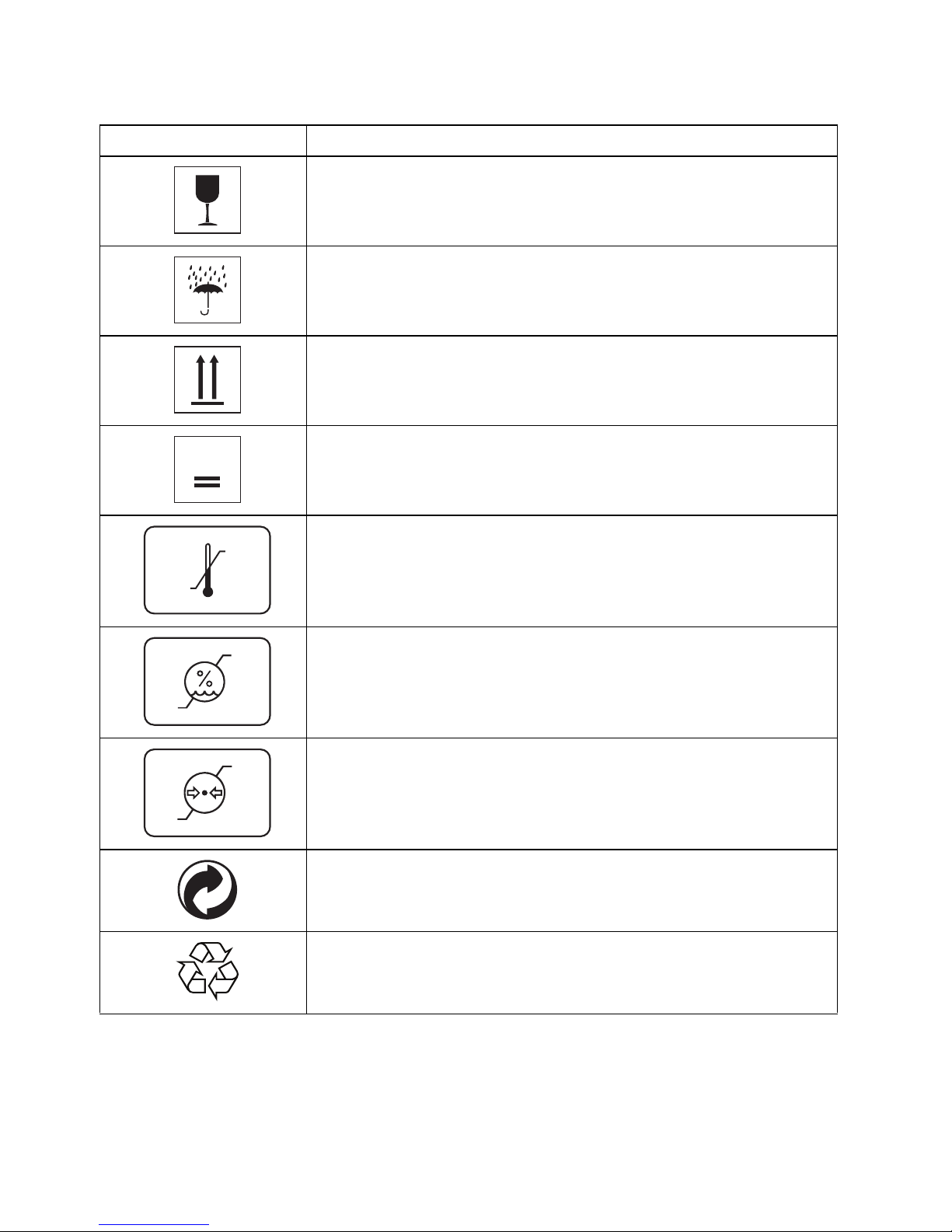
Symbols on the Box . . . . . . . . . . . . . . . . . . . . . . . . . . . . . . 6
Intended Use . . . . . . . . . . . . . . . . . . . . . . . . . . . . . . . . . . . . 7
Warning. . . . . . . . . . . . . . . . . . . . . . . . . . . . . . . . . . . . . . . . . 7
Regulatory compliance information . . . . . . . . . . . . . . . . 9
EMC notice . . . . . . . . . . . . . . . . . . . . . . . . . . . . . . . . . . . . 10
2 About Your Monitor . . . . . . . . . . . . . . . . . . . . . . . .13
Package Contents . . . . . . . . . . . . . . . . . . . . . . . . . . . . . . . 13
Product Features . . . . . . . . . . . . . . . . . . . . . . . . . . . . . . . 15
Identifying Parts and Controls . . . . . . . . . . . . . . . . . . . . 16
Monitor Specifications . . . . . . . . . . . . . . . . . . . . . . . . . . . 19
Plug and Play Capability . . . . . . . . . . . . . . . . . . . . . . . . .28
Universal Serial Bus (USB) Interface . . . . . . . . . . . . . . . .28
LCD Monitor Quality and Pixel Policy. . . . . . . . . . . . . . .29
Cleaning Your Monitor . . . . . . . . . . . . . . . . . . . . . . . . . .30
3 Setting Up the Monitor . . . . . . . . . . . . . . . . . . . . .31
Connecting Your Monitor. . . . . . . . . . . . . . . . . . . . . . . . . 31
Attaching the Cable Cover. . . . . . . . . . . . . . . . . . . . . . . . 33
Attaching the Stand. . . . . . . . . . . . . . . . . . . . . . . . . . . . . .34
Organizing Your Cables . . . . . . . . . . . . . . . . . . . . . . . . . .36
Connecting the Computer. . . . . . . . . . . . . . . . . . . . . . . .36
Removing the Monitor Stand. . . . . . . . . . . . . . . . . . . . . . 37
Removing the Cable Cover . . . . . . . . . . . . . . . . . . . . . . . 37
Wall Mounting (Optional) . . . . . . . . . . . . . . . . . . . . . . . . .38
4 Operating the Monitor. . . . . . . . . . . . . . . . . . . . . 39
Power On the Monitor . . . . . . . . . . . . . . . . . . . . . . . . . . .39
Using the Front Panel Controls . . . . . . . . . . . . . . . . . . . .39
Using the On-Screen Display (OSD) Menu . . . . . . . . . . 41
Setting the Maximum Resolution . . . . . . . . . . . . . . . . . .54
Using the Tilt, Swivel, and Vertical Extension . . . . . . . . 55

4| Contents
Rotating the Monitor. . . . . . . . . . . . . . . . . . . . . . . . . . . . . 56
Adjusting the Rotation Display Settings of Your
System . . . . . . . . . . . . . . . . . . . . . . . . . . . . . . . . . . . . . . . .58
5 Troubleshooting . . . . . . . . . . . . . . . . . . . . . . . . . . 59
Self-Test . . . . . . . . . . . . . . . . . . . . . . . . . . . . . . . . . . . . . . .59
Built-in Diagnostics. . . . . . . . . . . . . . . . . . . . . . . . . . . . . .60
Common Problems. . . . . . . . . . . . . . . . . . . . . . . . . . . . . . 61
Product Specific Problems. . . . . . . . . . . . . . . . . . . . . . . .63
Universal Serial Bus (USB) Specific Problems . . . . . . . .64
6 Appendix . . . . . . . . . . . . . . . . . . . . . . . . . . . . . . . . . 65
Contact Dell . . . . . . . . . . . . . . . . . . . . . . . . . . . . . . . . . . . .65
Setting Up Your Monitor. . . . . . . . . . . . . . . . . . . . . . . . . .65

Safety Information | 5
Safety Information
WARNING: Safety Instructions
WARNING: Use of controls, adjustments, or procedures other than those
specified in this documentation may result in exposure to shock, electrical
hazards, and/or mechanical hazards.
Please read safety and instructions for use before operating the device.
Please retain this user's guide for future reference.
For information on safety instructions, see the Safety, Environmental, and Regulatory
Information.
Symbols on the Device
Symbol Location Explanation
Rear Indicates manufacture’s serial number.
Rear Indicates the date of manufacture.
Rear This device complies with local regulations for disposal
of electronic products.
Rear Follow operating instructions for use.
Rear This device complies with Part 15 Class B of the FCC
rules.
Rear Indicates Direct Current (DC).
Rear Indicates the device is approved according to the
cTUVus regulations.

Symbol Explanation
Contents of the transport package are fragile therefore it
shall be handled with care.
Transport package shall be kept away from rain.
Indicates correct upright position of the transport package.
5
Maximum number of identical packages that may be
stacked, where “n” stands for the number of permitted
packages
-xx°C
+yy°C
Indicates temperature limits within which the transport
package shall be stored and handled.
NOTE: Values for “xx” and “yy” can be found in the
Environmental Characteristics
section.
x%
yy%
Humidity limitation should be indicated adjacent to the
upper and lower horizontal lines.
NOTE: Values for “xx” and “yy” can be found in the
Environmental Characteristics
section.
xxxhPa
yyyyhPa
Atmospheric pressure limitation should be indicated
adjacent to the upper and lower horizontal lines.
NOTE: Values for “xx” and “yy” can be found in the
Environmental Characteristics
section.
Indicates that the fee has been paid for the recovery of the
packaging material in some European countries.
Indicates that an object is capable of being recycled.
6| Safety Information
Symbols on the Box

Safety Information | 7
Intended Use
MR2217 is an LCD display intended used for trained physician or practitioners viewing
medical images and data in hospital or clinic environment.
The device is neither used for life supporting system, surgical procedure system nor
viewing digital mammography images.
Warning
You may get an electric shock if the AC outlet is not grounded properly.
Disconnecting Device
The power cord is the disconnect device for this monitor and is attached to the power
adapter as a plug-in device. To remove all electrical power from the monitor, disconnect
the power cord from the electrical outlet.
General recommendations
•For continued safe use of this monitor, read the safety and operating instructions
before operating the monitor.
•Unplug the AC mains cord to disconnect the mains power.
•Use only the power cord supplied with this monitor.
•Adhere to all warnings on the device and in the operating instructions manual.
Electrical Shock or Fire Hazard
•Connect the AC power cord to a properly grounded power source with the line
frequency and voltage specified on the name plate of the power adapter.
•To reduce the risk of electrical shock, DO NOT remove any covers. Refer servicing
to qualified personnel only.
•Users must not allow SIP/SOPs and the patient to come into contact at the same
time.
Modifications to the unit
No modification of this monitor is allowed.
Type of protection (electrical)
Monitor with external power adapter: Class I equipment.
Explosion Hazard
Do not use this monitor in the presence of flammable materials.

8| Safety Information
Power connection - Monitor with external +19VDC power
adapter
•Power requirements: The monitor must be powered using the accompanied
medical- approved power adapter.
•The medical-approved power adapter must be powered by AC mains power.
•The power adapter is specified as a part of the monitor.
Power cord
•Do not use extension cords as this may result in fire or electric shock.
•Use the power cord that is supplied with the monitor only.
NOTE: Grounding reliability can only be achieved when the equipment is
connected to an equivalent receptacle marked “Hospital Only” or “Hospital Grade”.
Connection of External Equipment
•External equipment intended for connection to signal input/output or other
connectors, shall comply with relevant UL/EN/IEC standard (e.g. UL/EN/IEC 60950
for IT equipment and UL/EN 60601-1/IEC 60601 series for medical electrical
equipment).
•In addition, all such combinations -systems- shall comply with the standard IEC
60601-1-1, safety requirements for medical electrical systems.
•Equipment not complying with UL/EN/IEC 60601-1 shall be kept outside the
patient environment, as defined in the standard.

Safety Information | 9
Regulatory compliance information
INDICATION FOR USE
MR2217 is an LCD display intended used for trained physician or practitioners viewing
medical images and data in hospital or clinic environment.
The device neither be used for life supporting system, surgical procedure system nor
viewing digital mammography images.
FCC Information
Federal Communications Commission (FCC) Notice (U.S. Only) WARNING: This
equipment has been tested and found to comply with the limits for a digital device,
pursuant to Part 15 Class B of the FCC Rules. These limits are designed to provide
reasonable protection against harmful interference in a residential installation. This
equipment generates, uses, and can radiate radio frequency energy and, if not installed
and used in accordance with the instructions, may cause harmful interference to radio
communications. However, there is no guarantee that interference will not occur in a
particular installation. If this equipment does cause harmful interference to radio or
television reception, which can be determined by turning the equipment off and on, the
user is encouraged to try to correct the interference by one or more of the following
measures:
•Reorient or relocate receiving antenna.
•Increase the separation between the equipment and receiver.
•Connect the equipment into an outlet on a circuit different from that to which the
receiver is connected.
•Consult the dealer or an experienced radio/TV technician for help.
This device complies with Part 15 Class B of the FCC rules. Operation is subject to the
following two conditions:
•This device may not cause harmful interference.
•This device must accept any interference received including interference that may
cause undesired operation.
CAUTION: Changes or modifications not expressly approved by the party responsible
for compliance could void the user's authority to operate the equipment.
CANADIAN NOTICE
This ISM device complies with Canadian ICES-003.

10 | Safety Information
EMC notice
Electromagnetic emissions
The MR2217 is intended for use in the electromagnetic environment specified below.
The customer or the user of the MR2217 should assure that it is used in such an
environment.
Emissions test Compliance Electromagnetic environment - Guidance
RF emissions
CISPR 11
Group 1 The MR2217 uses RF energy only for its internal
function.
Therefore, its RF emissions are very low and are
not likely to cause any interference in nearby
electronic equipment.
RF emissions
CISPR 11
Class B The MR2217 is suitable for use in all
establishments, including domestic
establishments and those directly connected to
the public low-voltage power supply network that
supplies buildings used for domestic purposes.
Harmonic emissions
IEC 61000-3-2
Class D
Voltage fluctuations/
flicker emissions
IEC 61000-3-3
Complies
Electromagnetic immunity
Immunity test IEC 60601 Test
levels
Compliance
level
Electromagnetic environment
- Guidance
Electrostatic
discharge (ESD)
IEC 61000-4-2
±6 kV contact
±8 kV air
±6 kV contact
±8 kV air
Floors should be wood, concrete
or ceramic tile. If floors are
covered with synthetic material,
the relative humidity should be at
least 30%.
Electrical fast
transient/burst
IEC 61000-4-4
±2 kV for power
supply lines
±1 kV for input/
output lines
±2 kV for power
supply lines
±1 kV for input/
output lines
Mains power quality should be that
of a typical commercial or hospital
environment.
Surge
IEC 61000-4-5
±1 kV line(s) to
line(s)
±2 kV line(s) to
earth
±1 kV line(s) to
line(s)
±2 kV line(s) to
earth
Mains power quality should be that
of a typical commercial or hospital
environment.

Safety Information | 11
Voltage dips, short
interruptions and
voltage variations
on power supply
input lines
IEC 61000-4-11
< 5% UT1 (> 95%
dip in UT) for 0.5
cycle
40% UT(60% dip
in UT) for 5 cycles
70% UT(30% dip
in UT) for 25
cycles
< 5% UT(>95%
dip in UT) for 5s
< 5% UT(> 95%
dip in UT) for 0.5
cycle
40% UT(60% dip
in UT) for 5 cycles
70% UT(30% dip
in UT) for 25
cycles
< 5% UT(>95% dip
in UT) for 5s
Mains power quality should be that
of a typical commercial or hospital
environment. If the user of the
MR2217 requires continued
operation during power mains
interruptions, it is recommended
that the MR2217 be powered from
an uninterruptible power supply or
a battery.
Power frequency
(50/60 Hz)
magnetic field
IEC 61000-4-8
3 A/m 3 A/m Power frequency magnetic fields
should be at least characteristic of
a typical location in a typical
commercial or hospital
environment.
Conducted RF
IEC 61000-4-6
Radiated RF
IEC 61000-4-3
3 Vrms
150 kHz to 80
MHz
3 V/m
80 MHz to 2.5
GHz
3 Vrms
3 V/m
Portable and mobile RF
communications equipment
should be used no closer to any
part of the OEV262H, including
cables, than the recommended
separation distance calculated
from the equation appliance to the
frequency of the transmitter.
Recommended separation
distance:
d = 1.2 √P
d = 1.2 √P 80 MHz to 800 MHz
d = 2.3 √P 800 MHz to 2.5 GHz
Where P is the maximum output
power rating of the transmitter in
watts (W) according to the
transmitter manufacturer and d is
the recommended separation
distance in meters (m).
Field strengths from fixed RF
transmitters, as determined by an
electromagnetic site surveya,
should be less than the
compliance level in each
frequency rangeb. Interference
may occur in the vicinity of
equipment marked with following
symbol:

12 | Safety Information
Recommended separation distance
The MR2217 display is intended for use in an electromagnetic environment in which
radiated RF disturbances are controlled. The customer of the user or the MR2217 display
can help prevent electromagnetic interference by maintaining a minimum distance
between portable and mobile RF communications equipment (transmitters) and the
MR2217 display as recommended below, according to the maximum output power of
the communications equipment.
Rated maximum
output power of
transmitter (W)
Separation distance according to frequency of transmitter (m)
150kHz to 80MHz
d=1.2√P
80MHz to 800MHz
d=1.2√P
800MHz to 2.5GHz
d=2.3√P
0.01 0.12 0.12 0.23
0.1 0.38 0.38 0.73
11.2 1.2 2.3
10 3.8 3.8 7.3
100 12 12 23
For transmitters rated at a maximum output power not listed above, the recommended
separation distance “d” in meters (m) can be estimated using the equation applicable to the
frequency of the transmitter, where “P” is the maximum output power rating of the transmitter in
watts (W) according to the transmitter manufacturer.
NOTE: At 80 MHz and 800 MHz, the separation distance for the higher frequency range applies.
NOTE: These guidelines may not apply in all situations. Electromagnetic propagation is affected by
absorption and reflection from structures, objects and people.
NOTE: At 80 MHz and 800 MHz, the higher frequency range applies.
NOTE: These guidelines may not apply in all situations. Electromagnetic propagation is affected by
absorption and reflection from structures, objects and people.
a. Field strengths from fixed transmitters, such as base stations for radio (cellular/cordless) tele-
phones and land mobile radios, amateur radio, AM and FM radio broadcast and TV broadcast can-
not be predicted theoretically with accuracy. To assess the electromagnetic environment due to
fixed RF transmitters, an electromagnetic site survey should be considered. If the measured field
strength in the location in which the MR2217 is used exceeds the applicable RF compliance level
above, the MR2217 should be observed to verify normal operation. If abnormal performance is
observed, additional measures may be necessary, such as reorienting or relocating the MR2217.
b. Over the frequency range 150 kHz to 80 MHz, field strengths should be less than 3 V/m.

About Your Monitor | 13
About Your Monitor
Package Contents
Your monitor ships with the components shown below. Ensure that you have received all
the components and
Contact Dell
if something is missing.
NOTE: Some items may be optional and may not ship with your monitor. Some
features or media may not be available in certain countries.
NOTE: To set up with any other stand, please refer to the respective stand setup
guide for setup instructions.
Monitor
Stand Riser
Stand Base
Cable Cover

DC Power Cable
Power Adapter
DP Cable
HDMI Cable
USB 2.0 Upstream Cable
(Enables the USB Ports on
the Monitor)
•Drivers and
Documentation Media
•Quick Setup Guide
•Safety, Environmental,
and Regulatory
Information
•Factory Calibration
Report
14 | About Your Monitor

About Your Monitor | 15
Product Features
The Dell MR2217 flat panel medical display has an active matrix, Thin-Film Transistor
(TFT), Liquid Crystal Display (LCD) and LED backlight. The monitor features include:
•54.61 cm (21.5-inch) viewable area display (measured diagonally).
1920 x 1080 resolution, plus full-screen support for lower resolutions.
•Wide viewing angle to allow viewing from a sitting or standing position, or while
moving from side-to-side.
•Tilt, swivel, height, and rotate adjustment capabilities.
•Removable stand and Video Electronics Standards Association (VESA™) 100 mm
mounting holes for flexible mounting solutions.
•Digital connectivity with DisplayPort and HDMI.
•Equipped with 1 USB upstream port and 2 USB downstream ports.
•Plug and play capability if supported by your system.
•On-Screen Display (OSD) adjustments for ease of set-up and screen optimization.
•Software and documentation media includes an Information File (INF), Image Color
Matching File (ICM), and product documentation.
•Dell Display Manager Software included (comes in the CD shipped with the
monitor).
•Security lock slot and cable clip.
•Capability to switch from wide aspect to standard aspect ratio while maintaining
the image quality.
•BFR/PVC/CFR-free (Halogen-free) excluding the external cables and power
adapter.
•Meets NFPA 99 leakage current requirements.
•Arsenic-Free glass and Mercury-Free for the panel only.
•0.5 W standby power when in the sleep mode.
•Energy Gauge shows the energy level being consumed by the monitor in real time.
•Analog backlight dimming control for flicker free display.
•DICOM (Digital Imaging and Communications in Medicine) part-14 GFDS for
accurate grayscale reproducibility. DICOM calibrated luminance at 180 cd/m².
•FDA Class I and medical grade display.
•Integrated backlight sensing for brightness stabilization.
•Cable security and management.
•10-bit LUT and color processing.
•White housing for visible dried blood stains detection.

16 | About Your Monitor
Identifying Parts and Controls
Front View
Front panel controls
Label Description
1Function buttons (For more information, see
Operati ng the Monitor
)
2Power On/Off button (with LED indicator)
Side View

About Your Monitor | 17
Back View
Back view with monitor stand
Label Description Use
1VESA mounting holes
(100 mm x 100 mm -
behind attached VESA
Cover)
Wall mount monitor using VESA-compatible wall
mount kit (100 mm x 100 mm).
2Regulatory label Lists the regulatory approvals.
3Stand release button Releases stand from monitor.
4Security lock slot Supports the use of security lock to prevent theft.
(security lock not included)
5Cable cover Offers the protection to the installed cables on the
rear of the monitor.
6Barcode serial number
label
Refer to this label if you need to contact Dell for
technical support.
7Cable clip Use to secure the cables by tightening the screw
on the clip.
8Cable management slot Use to organize cables by placing them through
the slot.

Bottom view without monitor stand
Label Description Use
1Adapter connector Connect the power cable.
2DisplayPort in
connector
Connect your computer with DP cable.
3HDMI port connector Connect your computer with HDMI cable.
4VGA connector Connect your computer with VGA cable (cable not
included).
5USB upstream port Connect the USB cable that came with your monitor
to the monitor and the computer. Once this cable is
connected, you can use the USB connectors on the
monitor.
6USB downstream port Connect your USB device. You can only use this
connector after you have connected the USB cable to
the computer and USB upstream connector on the
monitor.
7Stand release button Releases stand from monitor.
18 | About Your Monitor
Bottom View

About Your Monitor | 19
Monitor Specifications
Flat Panel Specifications
Model MR2217
Screen type Active matrix - TFT LCD
Panel type In-Plane Switching type
Viewable image
Diagonal
Horizontal, Active Area
Vertical, Active Area
Area
546.1 mm (21.5 inches)
476.06 mm (18.74 inches)
267.78 mm (10.54 inches)
127479.35 mm2(197.59 inch2)
Pixel pitch 0.248 mm x 0.248 mm
Viewing angle 178° (vertical) typical
178° (horizontal) typical
Luminance output 250 cd/m² (typical)
Contrast ratio 1000 to 1 (typical)
Faceplate coating Anti-Glare with 3H hardness
Backlight LED edgelight system
Response time 14 ms (Gray to Gray)
Color depth 16.7 million colors
Color gamut 72% (typical)*
* MR2217 color gamut (typical) is based on CIE1976 (85%) and CIE1931 (72%) test
standards.

Model MR2217
Horizontal scan range 30 kHz to 83 kHz (automatic)
Vertical scan range 50 Hz to 76 Hz (automatic)
Maximum preset resolution 1920 x 1080 at 60 Hz
20 | About Your Monitor
Resolution Specifications
Preset Display Modes
Display Mode Horizontal
Frequency (kHz)
Vertical
Frequency
(Hz)
Pixel Clock
(MHz)
Sync Polarity
(Horizontal/
Vertical)
VESA, 720 x 400 31.5 70.1 28.3 -/+
VESA, 640 x 480 31.5 60.0 25.2 -/-
VESA, 640 x 480 37.5 75.0 31.5 -/-
VESA, 800 x 600 37.9 60.3 40.0 +/+
VESA, 800 x 600 46.9 75.0 49.5 +/+
VESA, 1024 x 768 48.4 60.0 65.0 -/-
VESA, 1024 x 768 60.0 75.0 78.8 +/+
VESA, 1152 x 864 67.5 75.0 108.0 +/+
VESA, 1280 x 1024 63.9 60.0 108.0 +/+
VESA, 1280 x 1024 80.0 75.0 135.0 +/+
VESA, 1600 x 900 60.0 60.0 108.0 +/+
VESA, 1920 x 1080 67.5 60.0 148.5 +/+
Table of contents
Other Dell Monitor manuals

Dell
Dell S2240T User manual

Dell
Dell Alienware AW2521H User manual

Dell
Dell U2415 User manual

Dell
Dell UltraSharp U3421WE User manual

Dell
Dell P2422HB User manual

Dell
Dell UP2720QB User manual

Dell
Dell S2317HWI User manual

Dell
Dell TORINITRON P1130 User manual

Dell
Dell U2720Q User manual

Dell
Dell P2418HZM User manual