manuals.online logo
Brands
  1. Home
  2. •
  3. Brands
  4. •
  5. Dell
  6. •
  7. Server
  8. •
  9. Dell PowerEdge 4350 User manual

Dell PowerEdge 4350 User manual

ZZZGHOOFRP
™
'HOO3RZHU(GJH
6\VWHP8SJUDGH
,167$//$7,21*8,'(
1RWHV1RWLFHV&DXWLRQVDQG:DUQLQJV
Throughout this guide, blocks of text may be accompanied by an icon and printed in
bold type or in italic type. These blocks are notes, notices, cautions, and warnings,
and they are used as follows:
NOTE: A NOTE indicates important information that helps you make better use of
your computer system.
127,&($127,&(LQGLFDWHVHLWKHUSRWHQWLDOGDPDJHWRKDUGZDUHRUORVV
RIGDWDDQGWHOOV\RXKRZWRDYRLGWKHSUREOHP
&$87,21$&$87,21LQGLFDWHVDSRWHQWLDOO\KD]DUGRXVVLWXDWLRQZKLFKLI
QRWDYRLGHGPD\UHVXOWLQPLQRURUPRGHUDWHLQMXU\
:$51,1*$:$51,1*LQGLFDWHVDSRWHQWLDOO\KD]DUGRXVVLWXDWLRQZKLFK
LIQRWDYRLGHGFRXOGUHVXOWLQGHDWKRUVHULRXVERGLO\LQMXU\
____________________
Information in this document is subject to change without notice.
© 1999 Dell Computer Corporation. All rights reserved.
Reproduction in any manner whatsoever without the written permission of Dell Computer Corpo-
ration is strictly forbidden.
Trademarks used in this text:
Dell
,
PowerEdge
, and the
DELL
logo are trademarks of Dell
Computer Corporation;
Microsoft
and
Windows NT
are registered trademarks of Microsoft Cor-
poration;
Novell
and
NetWare
are registered trademarks of Novell, Inc.
Other trademarks and trade names may be used in this document to refer to either the entities
claiming the marks and names or their products. Dell Computer Corporation disclaims any propri-
etary interest in trademarks and trade names other than its own.
April 1999 P/N 3736D Rev. A00
iii
&RQWHQWV
Safety Caution and Warnings . . . . . . . . . . . . . . . . . . . . . . . . . . . . . . . . . . . . . . . . . . .1
Precautions for Rack-Mountable Products. . . . . . . . . . . . . . . . . . . . . . . . . . . . . .2
Protecting Against Electrostatic Discharge . . . . . . . . . . . . . . . . . . . . . . . . . . . . . . . . .3
Recommended Tools . . . . . . . . . . . . . . . . . . . . . . . . . . . . . . . . . . . . . . . . . . . . . . . . .3
Before You Begin . . . . . . . . . . . . . . . . . . . . . . . . . . . . . . . . . . . . . . . . . . . . . . . . . . . .4
Precautionary Measures . . . . . . . . . . . . . . . . . . . . . . . . . . . . . . . . . . . . . . . . . . . . . . .4
Removing the System From the Rack. . . . . . . . . . . . . . . . . . . . . . . . . . . . . . . . . . . . .5
Power Supply Installation . . . . . . . . . . . . . . . . . . . . . . . . . . . . . . . . . . . . . . . . . . . . . .5
Access to the Interior of the System. . . . . . . . . . . . . . . . . . . . . . . . . . . . . . . . . . . . . .6
Expansion Card Removal. . . . . . . . . . . . . . . . . . . . . . . . . . . . . . . . . . . . . . . . . . . . . . .7
I/O Panel Replacement . . . . . . . . . . . . . . . . . . . . . . . . . . . . . . . . . . . . . . . . . . . . . . . .9
System Fan Assembly Removal . . . . . . . . . . . . . . . . . . . . . . . . . . . . . . . . . . . . . . . . .9
System Cable Removal . . . . . . . . . . . . . . . . . . . . . . . . . . . . . . . . . . . . . . . . . . . . . . .11
System Board Removal. . . . . . . . . . . . . . . . . . . . . . . . . . . . . . . . . . . . . . . . . . . . . . .11
System Board Installation . . . . . . . . . . . . . . . . . . . . . . . . . . . . . . . . . . . . . . . . . . . . .13
System Cable Reinstallation . . . . . . . . . . . . . . . . . . . . . . . . . . . . . . . . . . . . . . . . . . .16
Memory Module Installation . . . . . . . . . . . . . . . . . . . . . . . . . . . . . . . . . . . . . . . . . . .20
Expansion Card Reinstallation . . . . . . . . . . . . . . . . . . . . . . . . . . . . . . . . . . . . . . . . . .21
System Label Replacement. . . . . . . . . . . . . . . . . . . . . . . . . . . . . . . . . . . . . . . . . . . .24
System Badge Replacement. . . . . . . . . . . . . . . . . . . . . . . . . . . . . . . . . . . . . . . . . . .24
Replacing the Computer in Its Rack . . . . . . . . . . . . . . . . . . . . . . . . . . . . . . . . . . . . .24
Operating System Updates for Multiple Microprocessors . . . . . . . . . . . . . . . . . . . .25
Microsoft Windows NT 4.0 . . . . . . . . . . . . . . . . . . . . . . . . . . . . . . . . . . . . . . . .25
Novell NetWare 4.1
x
. . . . . . . . . . . . . . . . . . . . . . . . . . . . . . . . . . . . . . . . . . . . .26
Novell NetWare 5.0 . . . . . . . . . . . . . . . . . . . . . . . . . . . . . . . . . . . . . . . . . . . . . .26
Excess Parts . . . . . . . . . . . . . . . . . . . . . . . . . . . . . . . . . . . . . . . . . . . . . . . . . . . . . . .27
iv
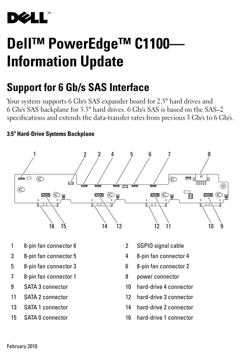
)LJXUHV Figure 1. Power Supply Installation . . . . . . . . . . . . . . . . . . . . . . . . . . . . . . . . . . .6
Figure 2. Access to the Interior of the System. . . . . . . . . . . . . . . . . . . . . . . . . . .7
Figure 3. Expansion Card Removal. . . . . . . . . . . . . . . . . . . . . . . . . . . . . . . . . . . .8
Figure 4. System Fan Assembly Removal . . . . . . . . . . . . . . . . . . . . . . . . . . . . .10
Figure 5. System Board Removal. . . . . . . . . . . . . . . . . . . . . . . . . . . . . . . . . . . . 12
Figure 6. Dell PowerEdge 6350 System Board Components. . . . . . . . . . . . . . . 13
Figure 7. System Board Jumpers. . . . . . . . . . . . . . . . . . . . . . . . . . . . . . . . . . . . 14
Figure 8. System Board Installation . . . . . . . . . . . . . . . . . . . . . . . . . . . . . . . . . . 15
Figure 9. System Cable Connections . . . . . . . . . . . . . . . . . . . . . . . . . . . . . . . . .17
Figure 10. Power-Supply Paralleling Board (PSPB) . . . . . . . . . . . . . . . . . . . . . . . 18
Figure 11. Diskette and CD-ROM Drive Connections . . . . . . . . . . . . . . . . . . . . . 19
Figure 12. Memory Module . . . . . . . . . . . . . . . . . . . . . . . . . . . . . . . . . . . . . . . . .20
Figure 13. PCI Expansion Cards . . . . . . . . . . . . . . . . . . . . . . . . . . . . . . . . . . . . . .21
Figure 14. Expansion-Card Connectors . . . . . . . . . . . . . . . . . . . . . . . . . . . . . . . . 22
Figure 15. Expansion Card Installation . . . . . . . . . . . . . . . . . . . . . . . . . . . . . . . . .23
Dell PowerEdge 4350 System Upgrade Installation Guide 1
'HOO3RZHU(GJH
6\VWHP8SJUDGH,QVWDOODWLRQ*XLGH
:$51,1*7KHSRZHUVXSSOLHVLQ\RXUFRPSXWHURUVWRUDJHV\VWHPPD\
SURGXFHKLJKYROWDJHVDQGHQHUJ\KD]DUGVZKLFKFDQFDXVHERGLO\KDUP
2QO\WUDLQHGVHUYLFHWHFKQLFLDQVDUHDXWKRUL]HGWRUHPRYHWKHFRPSXWHU
FRYHUVDQGDFFHVVDQ\RIWKHFRPSRQHQWVLQVLGHWKHFRPSXWHU
This guide provides instructions to upgrade your Dell PowerEdge 4350 system to a
Dell PowerEdge 6350 system.
Only trained service technicians should perform this upgrade; however, customers
can perform the software upgrade discussed in this guide.
The components that you need to upgrade the system include:
PowerEdge 6350 system board
Third redundant power supply
Hot-plug Peripheral Component Interconnect (PCI) expansion-card components
Associated data and power cables
System firmware
You also need to upgrade the following components (not included in this kit):
Microprocessor(s)
Memory
6DIHW\&DXWLRQDQG:DUQLQJV
Observe the following caution and warnings while servicing this system:
&$87,217KHUHLVDGDQJHURIDQHZEDWWHU\H[SORGLQJLILWLVLQFRUUHFWO\
LQVWDOOHG5HSODFHWKHEDWWHU\RQO\ZLWKWKHVDPHRUHTXLYDOHQWW\SHUHFRP
PHQGHGE\WKHPDQXIDFWXUHU'LVFDUGXVHGEDWWHULHVDFFRUGLQJWRWKH
PDQXIDFWXUHU·VLQVWUXFWLRQV
2 Dell PowerEdge 4350 System Upgrade Installation Guide
:$51,1*7KLVV\VWHPPD\KDYHPRUHWKDQRQHSRZHUVXSSO\FDEOH7R
UHGXFHWKHULVNRIHOHFWULFDOVKRFNDWUDLQHGVHUYLFHWHFKQLFLDQPXVWGLVFRQ
QHFWDOOSRZHUVXSSO\FDEOHVEHIRUHVHUYLFLQJWKHV\VWHP
3UHFDXWLRQVIRU5DFN0RXQWDEOH3URGXFWV
Observe the following precautions for rack stability and safety. Also refer to the rack
installation documentation accompanying the system and the rack for specific warn-
ing and/or caution statements and procedures.
:$51,1*,QVWDOOLQJ'HOOV\VWHPFRPSRQHQWVLQD'HOOUDFNZLWKRXWWKH
IURQWDQGVLGHVWDELOL]HUVLQVWDOOHGFRXOGFDXVHWKHUDFNWRWLSRYHUSRWHQ
WLDOO\UHVXOWLQJLQERGLO\LQMXU\XQGHUFHUWDLQFLUFXPVWDQFHV7KHUHIRUH
DOZD\VLQVWDOOWKHVWDELOL]HUVEHIRUHLQVWDOOLQJFRPSRQHQWVLQWKHUDFN
$IWHULQVWDOOLQJV\VWHPFRPSRQHQWVLQDUDFNQHYHUSXOOPRUHWKDQRQH
FRPSRQHQWRXWRIWKHUDFNRQLWVVOLGHDVVHPEOLHVDWRQHWLPH7KHZHLJKW
RIPRUHWKDQRQHH[WHQGHGFRPSRQHQWFRXOGFDXVHWKHUDFNWRWLSRYHUDQG
LQMXUHVRPHRQH
NOTE: Dell’s server and storage systems are certified as components for use in Dell’s
rack cabinet using the Dell customer rack kit. The final installation of Dell systems and
rack kits in any other brand of rack cabinet has not been approved by any safety agen-
cies. It is the customer’s responsibility to have the final combination of Dell systems
and rack kits for use in other brands of rack cabinets evaluated for suitability by a certi-
fied safety agency.
System rack kits are intended to be installed in a Dell rack by trained service tech-
nicians. If you install the kit in any other rack, be sure that the rack meets the
specifications of a Dell rack.
Do not move large racks by yourself. Due to the height and weight of the rack,
Dell recommends a minimum of two people to accomplish this task.
Before working on the rack, make sure that the stabilizers are secure to the rack,
extend to the floor, and that the full weight of the rack rests on the floor. Install
front and side stabilizers on a single rack or front stabilizers for joined multiple
racks before working on the rack.
Alwaysload the rackfromthebottomup, and loadtheheaviest itemintherackfirst.
Make sure that the rack is level and stable before extending a component from
the rack.
Extend only one component at a time from the rack.
Use caution when pressing the component rail release latches and sliding a com-
ponent into or out of a rack; the slide rails can pinch your fingers.
After a component is inserted into the rack, carefully extend the rail into a locking
position, and then slide the component into the rack.
Do not overload the AC supply branch circuit that provides power to the rack. The
total rack load should not exceed 80 percent of the branch circuit rating.
Dell PowerEdge 4350 System Upgrade Installation Guide 3
Ensure that proper airflow is provided to components in the rack.
Do not step on or stand on any system/component when servicing other sys-
tems/components in a rack.
3URWHFWLQJ$JDLQVW(OHFWURVWDWLF'LVFKDUJH
Static electricity can harm delicate components inside your computer. To prevent
static damage, discharge static electricity from your body before you touch any of
your computer’s electronic components, such as the processor. You can do so by
touching an unpainted metal surface on the computer chassis.
As you continue to work inside the computer, periodically touch an unpainted metal
surface to remove any static charge your body may have accumulated.
You can also take the following steps to prevent damage from electrostatic discharge
(ESD):
When unpacking a static-sensitive component from its shipping carton, do not
remove the component from the antistatic packing material until you are ready to
install the component in your computer. Just before unwrapping the antistatic
packaging, be sure to discharge static electricity from your body.
When transporting a sensitive component, first place it in an antistatic container
or packaging.
Handle all sensitive components in a static-safe area. If possible, use antistatic
floor pads and workbench pads.
The following notice may appear throughout this document to remind you of these
precautions:
127,&(6HH´3URWHFWLQJ$JDLQVW(OHFWURVWDWLF'LVFKDUJHµLQWKHVDIHW\
LQVWUXFWLRQVDWWKHIURQWRIWKLVJXLGH
5HFRPPHQGHG7RROV
To upgrade your PowerEdge 4350 system to a PowerEdge 6350 system, you need the
following tools:
#1 Phillips-head screwdriver
#2 Phillips-head screwdriver
1/4” nut driver
3/16” nut driver
Small flat-blade screwdriver
Needle-nose pliers
Use a wrist grounding strap as explained in “Precautionary Measures.”
4 Dell PowerEdge 4350 System Upgrade Installation Guide
%HIRUH<RX%HJLQ
Memory and processors for the PowerEdge 6350 system board are not supplied in
the upgrade kit; you must purchase them separately. Before you start the upgrade, be
sure that you have the correct processors and memory components to complete the
upgrade. Then perform the following steps:
1. Read the safety instructions in the previous section.
2. Provide for a suitable workspace that includes a place to unpack the upgrade kit,
a place to set the system while working on it, and a place to put the parts
removed from the system.
If an antistatic workbench pad is not available, be sure to follow all antistatic
precautions.
3. Verify the receipt and condition of all boxes and components.
4. Unpack the upgrade components.
5. Check and verify the physical condition of all upgrade components.
6. Verify that the system to be upgraded is a PowerEdge 4350 system.
3UHFDXWLRQDU\0HDVXUHV
Before you remove the computer covers, perform the following steps in the sequence
indicated.
127,&(6RPH'HOOV\VWHPVFDQEHVHUYLFHGRQO\E\WUDLQHGVHUYLFHWHFKQL
FLDQVEHFDXVHRIKLJKYROWDJHVDQGHQHUJ\KD]DUGV'RQRWDWWHPSWWR
VHUYLFHWKHFRPSXWHUV\VWHP\RXUVHOIH[FHSWDVH[SODLQHGLQWKLVJXLGHDQG
HOVHZKHUHLQ'HOOGRFXPHQWDWLRQ$OZD\VIROORZLQVWDOODWLRQDQGVHUYLFH
LQVWUXFWLRQVFORVHO\
127,&(7RKHOSDYRLGSRVVLEOHGDPDJHWRWKHV\VWHPERDUGZDLWVHF
RQGVDIWHUWXUQLQJRIIWKHV\VWHPEHIRUHUHPRYLQJDFRPSRQHQWIURPWKH
V\VWHPERDUGRUGLVFRQQHFWLQJDSHULSKHUDOGHYLFHIURPWKHFRPSXWHU
1. Turn off your computer and any peripherals.
2. Ground yourself by touching
an unpainted metal surface on the chassis, such as
the metal around the card-slot openings at the back of the computer, before
touching anything inside your computer.
While you work, periodically touch an unpainted metal surface on the computer
chassis to dissipate any static electricity that might harm internal components.
3. Disconnect
your computer and peripherals from their power sources. Also, dis-
connect any telephone or telecommunication lines from the computer.
Doing so reduces the potential for personal injury or shock.
Dell PowerEdge 4350 System Upgrade Installation Guide 5
In addition, take note of these safety guidelines when appropriate:
When you disconnect a cable, pull on its connector or on its strain-relief loop, not
on the cable itself. Some cables have a connector with locking tabs; if you are dis-
connecting this type of cable, press in on the locking tabs before disconnecting
the cable. As you pull connectors apart, keep them evenly aligned to avoid bend-
ing any connector pins. Also, before you connect a cable, make sure that both
connectors are correctly oriented and aligned.
Handle components and cards with care. Don’t touch the components or con-
tacts on a card. Hold a card by its edges or by its metal mounting bracket. Hold a
component such as a processor chip by its edges, not by its pins.
5HPRYLQJWKH6\VWHP)URPWKH5DFN
To remove the PowerEdge 4350 system from its rack, perform the following steps:
1. Turn off the system.
2. Loosen the thumbscrews securing the system in its rack, and slide the system
forward, but do not remove the system from the rack.
3. Disconnect all external cables from the system.
&$87,21/LIWLQJWKHFRPSXWHUIURPWKHUDFNUHTXLUHVWZRSHRSOH
4. Remove the system from the rack and place it on a suitable work surface.
3RZHU6XSSO\,QVWDOODWLRQ
The computer is shipped with two or three power supplies, depending on its configu-
ration. The upgrade kit provides a third power supply, if one is needed. To install the
third power supply, perform the following steps:
1. Remove the plastic power supply slot filler.
2. Install the new power supply.
When you install a power supply, make sure that the handle is all the way out (at
a right angle to the back of the power supply).
a. Slide the power supply
almost
all the way into its bay, letting it extend out
about a half centimeter (quarter of an inch).
b. Rotate the handle back toward the power supply while fitting the two legs of
the handle into the slots in the chassis wall, while at the same time pressing
the power supply the rest of the way into the bay.
6 Dell PowerEdge 4350 System Upgrade Installation Guide
127,&(7KHSRZHUVXSSO\ZLOOQRWRSHUDWHXQOHVVWKHKDQGOHLV
VQDSSHGDOOWKHZD\LQWRWKHVHFXULQJSRVLWLRQ
c. Push the power supply handle down until its latch clicks into place, securing
the power supply (see Figure 1).
)LJXUH3RZHU6XSSO\,QVWDOODWLRQ
$FFHVVWRWKH,QWHULRURIWKH6\VWHP
The computer has two panel doors on the top of the system that provide access to
the system board, memory, processors, and expansion cards. The right panel door
provides access to the expansion slots; the left panel door opens to the processor and
memory (see Figure 2). The doors interlock so that the keylock on the right panel door
secures both doors and the fan assembly.
power supply handle
power supply
chassis slots
(one each side)
power supply switch
“press here”
symbol
Dell PowerEdge 4350 System Upgrade Installation Guide 7
)LJXUH$FFHVVWRWKH,QWHULRURIWKH6\VWHP
To open the computer panel doors, perform the following steps:
1. Using the system key, unlock the keylock on the right panel door.
2. Press the two slide latches to release the right panel door and lift the door.
3. Lift the left panel door.
([SDQVLRQ&DUG5HPRYDO
127,&(6HH´3URWHFWLQJ$JDLQVW(OHFWURVWDWLF'LVFKDUJHµLQWKHVDIHW\
LQVWUXFWLRQVDWWKHIURQWRIWKLVJXLGH
To remove the expansion cards, perform the following steps:
1. Disconnect any cables attached to the expansion cards.
2. Release the expansion-card clip at the slot end of the expansion card:
a. On the back of the system, press and hold the clip that secures the
expansion card that you are removing (see 1 in Figure 3).
left panel door
panel door keylock
slide
latches (2)
right panel
door
expansion slots
system key
8 Dell PowerEdge 4350 System Upgrade Installation Guide
)LJXUH([SDQVLRQ&DUG5HPRYDO
b. Press down on the release tab on the clip inside the system (see 2 in
Figure 3).
c. Rotate the latch away from the expansion-card bracket (see 3 in Figure 3).
3. Depending on the type of card guide your system uses for the inner end of the
expansion card, use one of the following methods to release the guide latch
(see 4 in Figure 3).
127,&('RQRWXVHDWRROWRIRUFHWKHODWFKRSHQ
— For card guides with a squeeze latch, squeeze and rotate the top of the card
guide to release the latch.
— For card guides with a thumb latch, rotate the tab outward (away from the
expansion card) to release the latch.
4. Grasp the expansion card by its top corners, and carefully remove it from the
expansion-card connector.
expansion card
release tab
expansion-
card latch
card guide (thumb-latch type)
card guide (squeeze-
latch type)
expansion-
card clip
expansion-
card bracket
Dell PowerEdge 4350 System Upgrade Installation Guide 9
,23DQHO5HSODFHPHQW
To replace the input/output (I/O) panel, perform the following steps:
1. Remove any remaining expansion slot fillers.
2. Remove the seven screws that hold the I/O panel to the chassis.
Two screws are located on the right side of the computer; five are located on the
back.
3. Lift off the I/O panel.
4. Position the new I/O panel on the chassis.
5. Replace the two screws on the side and four screws on the back.
The remaining screw is not used.
Expansion slot filler panels are replaced when you reinstall the expansion cards.
6. Install the hot-plug PCI indicator card:
a. Place the hot-plug PCI gasket on the hot-plug PCI indicator so that the light-
emitting diodes (LEDs) show through the holes in the gasket.
b. Position the card on the I/O panel so that the two holes in the card are
aligned with the corresponding holes in the panel. The end of the card with
the ribbon cable attached should be nearest to the processor(s). Secure the
card with two push rivets.
6\VWHP)DQ$VVHPEO\5HPRYDO
To remove the fan assembly, grasp the recessed grip slot at the top of the fan assem-
bly, press in on the release lever inside the slot, and lift the fan assembly from the
system (see Figure 4).
10 Dell PowerEdge 4350 System Upgrade Installation Guide
)LJXUH6\VWHP)DQ$VVHPEO\5HPRYDO
Inspect the fan assembly cavity for the air dam shroud, which is located at the right
edge of the third power supply. The air dam shroud is a black plastic fin that redirects
air around the upgrade memory board.
If the air dam shroud is not installed, perform the following steps:
1. Remove the front bezel.
See “Front Bezel” in Chapter 4 of the
Service Manual
for more information.
2. Remove the top-cover panel.
See “SCSI Backplane” in Chapter 4 of the
Service Manual
for more information.
3. Orient the air dam shroud as shown in Figure 4.
4. Press air dam shroud in to latch it in place.
5. Replace the top-cover panel.
6. Replace the bezel.
fan assembly
grip slot
(release lever
inside the slot)
fan assembly
air dam shroud
Dell PowerEdge 4350 System Upgrade Installation Guide 11
6\VWHP&DEOH5HPRYDO
To remove the system cables, perform the following steps:
1. Remove the center brace.
The center brace is secured by two screws on the right side of the chassis and
one screw on the left, and both ends of the brace are hooked into the chassis
walls. Remove the screws and work the brace up out of the chassis (see
Figure 5).
2. Disconnect all internal cables from the system board.
Place the cable ends out of the way.
3. Disconnect the cables labeled “POWER1” and “POWER2” from the power-
supply paralleling board (PSPB) (see Figure 9), and remove them from the
system.
4. Disconnect the 68-pin Ultra2/low voltage differential (LVD) small computer sys-
tem interface (SCSI) cable from the SCSI backplane connector labeled “SCSI A,”
and remove it from the system.
5. Disconnect the 50-pin Ultra/Narrow SCSI cable from the CD-ROM drive, and
remove it from the system.
6\VWHP%RDUG5HPRYDO
127,&(6HH´3URWHFWLQJ$JDLQVW(OHFWURVWDWLF'LVFKDUJHµLQWKHVDIHW\
LQVWUXFWLRQVDWWKHIURQWRIWKLVJXLGH
To remove the system board from the chassis, perform the following steps:
1. Remove the six screws that hold the system board tray to the bottom of the
chassis (three screws on each side).
2. Lift up slightly on the system board tray.
3. Tilt the system board tray up toward the right side of the chassis and lift it out of
the chassis (see Figure 5).
12 Dell PowerEdge 4350 System Upgrade Installation Guide
)LJXUH6\VWHP%RDUG5HPRYDO
system board tray
thumbscrew
center brace
system board tray
screws (6)
center-brace screws (3)
Dell PowerEdge 4350 System Upgrade Installation Guide 13
6\VWHP %RDUG,QVWDOODWLRQ
Figure 6 shows the connectors and jumpers on the new system board.
)LJXUH'HOO3RZHU(GJH6\VWHP%RDUG&RPSRQHQWV
To install the new system board, perform the following steps.
NOTE: Memory and processors for the PowerEdge 6350 system board are not sup-
plied in the upgrade kit; you must purchase them separately.
video connector (VGA)
parallel port connector
(PARALLEL [top]) and
serial port connectors (2)
(SERIAL1 and SERIAL2)
keyboard and
mouse connectors
(KYBD/MOUSE)
diskette-drive interface
connector (FLOPPY)
battery connector (BATTERY)
Ultra/Narrow SCSI
connector
(SECONDARY SCSI)
speed and
configuration jumpers
front of system board
processors (4)
(PROC_1 [top] through
PROC_4)
32-bit PCI connectors
(PCI1 [top] through PCI3)
power input
connector (POWER1)
Ultra2/LVD SCSI
connector (PRIMARY
SCSI-B)
SCSI backplane board
interfacecableconnector
(BACKPLANE)
server management bus
connector (XSMB_IN)
fan connector (FAN3)
server management bus
connector (XSMB_OUT)
Dell Remote Assistant
Card connector (SVR_MGT)
PCI activity indicator card
connector (PCILEDPNL)
Ultra2/LVD SCSI
connector (PRIMARY
SCSI-A)
power input
connector (POWER2)
power input
connector (POWER3)
64-bit PCI connectors
(PCI4 through PCI7)
memory board
connector (MEMORY_BD)
fan connectors
(FAN1, FAN2)
chassis intrusion switch
connector (INTRUS2)
memory and I/O
bridge controller chip
14 Dell PowerEdge 4350 System Upgrade Installation Guide
127,&(6HH´3URWHFWLQJ$JDLQVW(OHFWURVWDWLF'LVFKDUJHµLQWKHVDIHW\
LQVWUXFWLRQVDWWKHIURQWRIWKLVJXLGH
1. Carefully remove the system board from its packaging material.
2. Verify that the jumpers are set as shown in Figure 7 except for the speed jumper,
which should be set to the speed of the processor(s).
)LJXUH6\VWHP%RDUG-XPSHUV
jumpered
unjumpered
Dell PowerEdge 4350 System Upgrade Installation Guide 15
3. Position the system board assembly over the chassis (see Figure 8).
4. Tilt the assembly down to the left, and position it inside the bottom of the
chassis.
5. Replace the six screws (three on each side).
)LJXUH6\VWHP%RDUG,QVWDOODWLRQ
system board
memory module memory retention bracket
thumbscrew
center brace
system fan assembly
center-brace screws (3)
system board tray
screws (6)
system-board
connectors
expansion-card
connectors
memory-
board
connector
16 Dell PowerEdge 4350 System Upgrade Installation Guide
6. Install the processor(s).
The processors are supplied separately from the system upgrade kit. For informa-
tion on installing a processor, refer to “Upgrading the Microprocessor or
Installing an Additional Microprocessor” in Chapter 8 of the system’s
Installation
and Troubleshooting Guide
.
When you install the processor(s), verify that all of them are the same speed, and
verify that the speed jumper is set to this speed (see Figure 7).
7. Install terminator cartridges in any unoccupied processor sockets.
The terminator cartridges are supplied separately from the system upgrade kit.
For information on installing a terminator cartridge, refer to “Upgrading the Micro-
processor or Installing an Additional Microprocessor” in Chapter 8 of the
system’s
Installation and Troubleshooting Guide
.
6\VWHP&DEOH5HLQVWDOODWLRQ
NOTE: The system cables that are routed underneath the system fan assembly are
labeled for their correct installation order.
To reinstall the system cables, perform the following steps:
1. Connect the 50-pin data cable in the upgrade kit to the CD-ROM drive.
2. Connect the 68-pin data cable in the upgrade kit to the SCSI backplane connector
labeled “SCSI A.”
3. Connect the data cable from the CD-ROM drive to the connector labeled “SEC-
ONDARY SCSI” on the system board.
4. Connect the 68-pin data cable from the SCSI backplane to the connector labeled
“PRIMARY SCSI A” on the system board (see Figure 9).

Other manuals for PowerEdge 4350

4

Other Dell Server manuals

Dell PowerEdge 2800 Manual

Dell

Dell PowerEdge 2800 Manual

Dell DX6000G User manual

Dell

Dell DX6000G User manual

Dell PowerEdge M630p User manual

Dell

Dell PowerEdge M630p User manual

Dell PowerEdge R250 VN927 Manual

Dell

Dell PowerEdge R250 VN927 Manual

Dell PowerEdge FN410S User manual

Dell

Dell PowerEdge FN410S User manual

Dell PowerEdge 2900 User manual

Dell

Dell PowerEdge 2900 User manual

Dell PowerEdge R715 User manual

Dell

Dell PowerEdge R715 User manual

Dell EMC PowerEdge R240 Manual

Dell

Dell EMC PowerEdge R240 Manual

Dell VMware ESX Server 3i User manual

Dell

Dell VMware ESX Server 3i User manual

Dell PowerEdge UPS 500T User manual

Dell

Dell PowerEdge UPS 500T User manual

Dell PowerEdge 1855 User manual

Dell

Dell PowerEdge 1855 User manual

Dell PowerEdge T420 User manual

Dell

Dell PowerEdge T420 User manual

Dell G0N7D Manual

Dell

Dell G0N7D Manual

Dell PowerEdge SC1435 User manual

Dell

Dell PowerEdge SC1435 User manual

Dell 6100 User manual

Dell

Dell 6100 User manual

Dell POWER EDGE SC1430 User manual

Dell

Dell POWER EDGE SC1430 User manual

Dell Wyse 5020 P Series User manual

Dell

Dell Wyse 5020 P Series User manual

Dell PowerEdge 750 User manual

Dell

Dell PowerEdge 750 User manual

Dell PowerEdge R220 User manual

Dell

Dell PowerEdge R220 User manual

Dell PowerEdge 3YPMN User manual

Dell

Dell PowerEdge 3YPMN User manual

Dell EMC ScaleIO Ready Node 14G User manual

Dell

Dell EMC ScaleIO Ready Node 14G User manual

Dell PowerEdge 1955 User manual

Dell

Dell PowerEdge 1955 User manual

Dell PowerEdge R410 User manual

Dell

Dell PowerEdge R410 User manual

Dell EMC VxFlex Ready Node 13G User manual

Dell

Dell EMC VxFlex Ready Node 13G User manual

Popular Server manuals by other brands

Siemens SINUMERIK 840D sl operating instructions

Siemens

Siemens SINUMERIK 840D sl operating instructions

TRENDnet TV-IP200W user guide

TRENDnet

TRENDnet TV-IP200W user guide

HP ProLiant ML115 G5 Integration notes

HP

HP ProLiant ML115 G5 Integration notes

Televes 718001 user manual

Televes

Televes 718001 user manual

Avocent Cyclades ACS Installation/administration/user guide

Avocent

Avocent Cyclades ACS Installation/administration/user guide

Oracle netra X5-2 Safety and compliance guide

Oracle

Oracle netra X5-2 Safety and compliance guide

Thecus N4100PRO user manual

Thecus

Thecus N4100PRO user manual

Acer Altos RM900 installation guide

Acer

Acer Altos RM900 installation guide

Oracle SPARC T5-1B Service manual

Oracle

Oracle SPARC T5-1B Service manual

HP ProLiant ML350 Generation 5 specification

HP

HP ProLiant ML350 Generation 5 specification

Alcatel Tier-1 T-Server manual&nbsp;

Alcatel

Alcatel Tier-1 T-Server manual&nbsp;

Sun Microsystems Ultra Enterprise 6000 Systems System manual

Sun Microsystems

Sun Microsystems Ultra Enterprise 6000 Systems System manual

Polycom SpectraLink 1725-36032-001 Administration guide

Polycom

Polycom SpectraLink 1725-36032-001 Administration guide

Advantech RS-200-RT user manual

Advantech

Advantech RS-200-RT user manual

Tiger Technology Tiger Box 1U8 Assembly guide

Tiger Technology

Tiger Technology Tiger Box 1U8 Assembly guide

HP ProLiant SL4545 Start guide

HP

HP ProLiant SL4545 Start guide

Dell EMC PowerEdge R840 Technical specifications

Dell EMC

Dell EMC PowerEdge R840 Technical specifications

HP AlphaServer GS1280 Systems specification

HP

HP AlphaServer GS1280 Systems specification

manuals.online logo
manuals.online logoBrands
  • About & Mission
  • Contact us
  • Privacy Policy
  • Terms and Conditions

Copyright 2025 Manuals.Online. All Rights Reserved.