dellonda DG5 User manual

Thank you for purchasing a Dellonda product. Manufactured to a high standard, this product will, if used according to these
instructions, and properly maintained, give you years of trouble free performance.
IMPORTANT: PLEASE READ THESE INSTRUCTIONS CAREFULLY. NOTE THE SAFE OPERATIONAL REQUIREMENTS, WARNINGS & CAUTIONS. USE
THE PRODUCT CORRECTLY AND WITH CARE FOR THE PURPOSE FOR WHICH IT IS INTENDED. FAILURE TO DO SO MAY CAUSE DAMAGE AND/OR
PERSONAL INJURY AND WILL INVALIDATE THE WARRANTY. KEEP THESE INSTRUCTIONS SAFE FOR FUTURE USE.
Original Language Version
Refer to
instruction
manual
PROPANEGASPYRAMIDPATIOHEATERS13KW
MODEL NO: DG5, DG6
1. SAFETY
9Read the installation, operating and maintenance instructions thoroughly before installing or using this equipment.
9 Ifthereisasmellofgas:shutothegastotheappliance,extinguishanyopenames.Ifodourcontinuescontactgassupplier.
8DO NOTstoreorusepetrolorotherammablesubstancesinsidethehousingoftheheater.
8DO NOTstoreorusepetrolorotherammableliquidsorgasesinthevicinityoftheheater.
8DO NOTstoreagascylinderthatisnotconnectedforuseinthevicinityofthisoranyotherappliance.
WARNING! DO NOTuseindoors.Foruseoutdoorsorinamplyventilatedareas.
Anamplyventilatedareaisonethathasaminimumof25%ofthesurfaceareaopen,seeg.1.
(Thesurfaceareaisthesumofthewallsurface.)
WARNING!Notintendedtobeinstalledinrecreationalvehiclesand/orboats.
WARNING!Improperinstallation,adjustment,alteration,serviceormaintenancecancauseinjuryor
propertydamage.
9 Installationandrepairmustbecarriedoutbyaqualiedperson.
8DO NOTattempttoalterinanyway.
9 Wearsafetyglovesduringtheassemblyprocess.
9 Thisproductmustbeinstalledandthegascylinderstoredinaccordancewiththelocalregulationsinforce.
8DO NOTobstructtheventilationholesofthecylinderhousing.
8DO NOTmove/transporttheappliancewheninoperation.Shutothegascylinderattheregulatorbeforemoving.
8DO NOTmove/transporttheheateruntilithascooleddown.
9 Useonlythetypeofgasandthetypeofcylinderspeciedbythemanufacturer.
TheLPcylinderusedwiththepatioheatermustmeetthefollowingsizerequirements:
Diameter31.8cmxheight58cm,15kgmaximumcapacity.
9 Protecttheproductfromstrongwindtopreventtilting.
9 Onlyuseonlevelground,capableofsupportingtheweightoftheheaterandthegascylinder.
8DO NOTconnectthegascylinderdirectlytotheappliancewithoutaregulator.Useonlythetypeofgasspeciedintheinstructions.
9 Thewholegassystem(hose,regulator,pilotorburner)shouldbeinspectedforleaksordamagebeforeuseandatleastannually,bya
suitablyqualiedperson.
9 Allleaktestingshouldbedonewithanappropriategasleakdetection/soapsolution.Neveruseanopenametocheckforleaks,refer
tosection6.2.
8DO NOTusetheheateruntilallconnectionshavebeenleaktested.
9 Turnothegasimmediatelyifagassmellisdetected.TurncylindervalveOFF.Iftheleakisatthehose/regulatorconnectiontighten
theconnectionandperformanotherleaktest.Ifbubblescontinueappearingcontactyoursupplier.Iftheleakisattheregulator/
cylinderconnectiondisconnectfromcylinder,reconnectandperformanotherleakcheck.Ifsoapbubblesarestillseen,cylindervalve
isdefective.Returncylindertoitsplaceofpurchase.
9 Keeptheventilationopeningofthecylinderenclosurefreeandclearofdebris.
8DO NOTpainttheradiantscreen,controlpanelortopcanopyreector.
9 Controlcompartment,burnerandcirculationairpassagewaysoftheheatermustbekeptclean.
9 Turnogaswhilstnotinuse.
9 LPregulator/hoseassemblymustbeaprotectedfromaccidentaldamage.
9 Anyguardremovedforservicing/maintenancemustbereplacedbeforeoperation.
9 Keepsadultsandchildrenawayfromthehightemperaturesurfaces,toavoidburnsandignitionofclothing.
9 Childrenshouldbecarefullysupervisedwhentheyareinthevicinityoftheheater.
8DO NOThangclothingorotherammablematerialsontheheaterorplacethemneartheheater.
2. INTRODUCTION
InnovativedesignofGasFlamePatioHeater.Contemporaryfreestandingpatioheateridealforbothcommercialanddomesticsettings
includingopenworkshops,boatyards,patios,forecourts,gardensandterraces.Standingat2.2mtall,whenlittheheaterproducesareal
ameencompassedbyaglasstubeandheatsthesurroundingarea. Metalreectormakessuretheheatisdirecteddownwardsandoutwards.
Variableheatoutputcontrolsmakeitfullyadjustable.Featuresafullyenclosedgascylinderchamberandsafetytipoverswitch.
g.1
DG5,DG6Issue:6(3,4,5)30/06/2021
Wearsafety
glovesduring
assembly

3. SPECIFICATION
Modelno’s............................................................. DG5,DG6
Fuel...........................................................................Propane
Fuelconsumption....................................................... 945g/hr
Heatedarea.....................................................................8m²
Output........................................................................... 13Kw
Dimensions(WxH)........................................580x2270mm
4. CONTENTS
Original Language Version
PART DESCRIPTION QTY.
A Reector 1
BFlame screen 1
CGlasstube 1
D Uppersupport 4
E Protectiveguard 4
FBlacksiliconering 1
G Sidepanel 3
H Frontpanel 1
IGas hose 1
J Controlboxassembly 1
K Lowersupport 4
L Blockbelt 1
M Wheelassembly 1
N Bottomplate 1
Max.gasbottlesize.......................................... Ø325x700mm
DG5,DG6Issue:6(3,4,5)30/06/2021
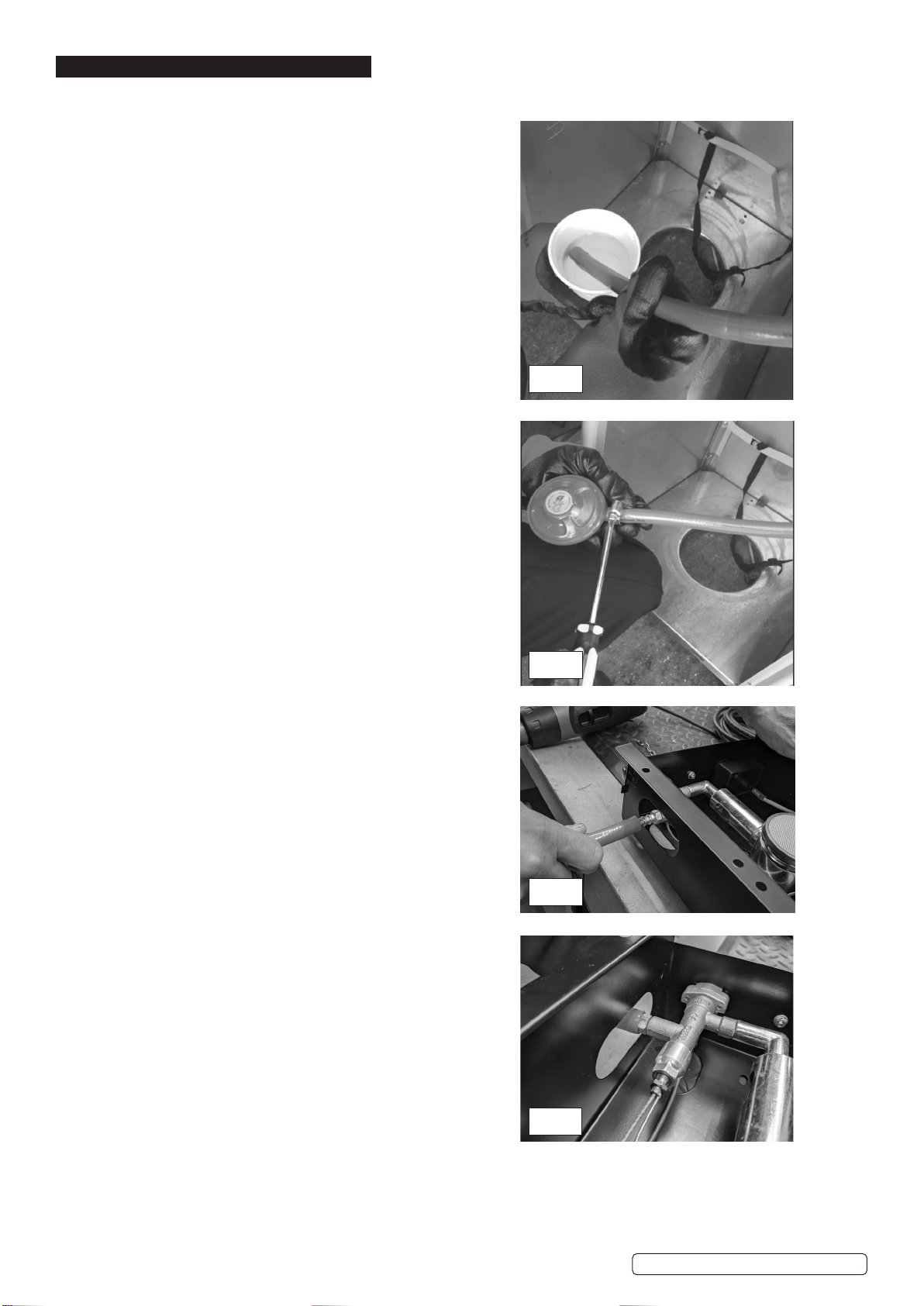
5.2. Toassistconnectingtheregulator,carefullyplacetherubberhoseintoan
insulatedcupofboilinghotwater(Fig.1).Thisallowstherubberhoseto
expand,ensurethehoseclipisslidoverthehoseandthenpushtheopen
hoseendfullyontothegasregulatorinlet.
5.3. Afterconnectingtheregulator,slidethehoseclipbacktoneartheendof
thehoseandtightenwithascrewdriver(Fig.2).
NOTE: Ensure you leak test this joint as directed in Section 6 after
assembly is complete and when you rst connect the gas bottle.
5.4. Now connect the open hose end to the control unit (J) again carefully place
the rubber hose end into an insulated cup of boiling hot water (Fig.1). This
allows the rubber hose to expand, ensure the hose clip is slid over the hose
and then push the open hose end fully onto the gas inlet on the control unit
as shown in Fig. 3.
5.5. Afterconnectingthehoseintothecontrolunit(J)slidethehoseclipbackto
neartheendofthehoseandtightenwithascrewdriver(Fig.2).
NOTE: Ensure you leak test this joint as directed in Section 6 after
assembly is complete and when you rst connect the gas bottle.
WARNING!Ensurefullengagementofhosetoregulatorandcontrol
unit.
WARNING!Checkthatthewormdriveclipsatbothendsofthegashose
arefullytightened.
WARNING! Arrangethegashoseandregulatortoensurethehosedoes
notcomeintocontactwithanyhightemperaturesurfacesasitmaymelt
andcauseare.Afterthecylinderisplacedinsidetheheater,tightly
securethecylinderwiththebelt.
NOTE:Seesection6forLeakCheckprocedure.
Original Language Version DG5,DG6Issue:6(3,4,5)30/06/2021
Fig.1
Fig.2
Fig.3
Fig.4
5. ASSEMBLY
5.1. Itisrecommendedthatyouconnectthegasregulatorhosetotheregulatorandthecontrolunit(J)priortoassemblingtheunit,becareful
nottodamageordislodgecomponentsinthecontrolunit(J).
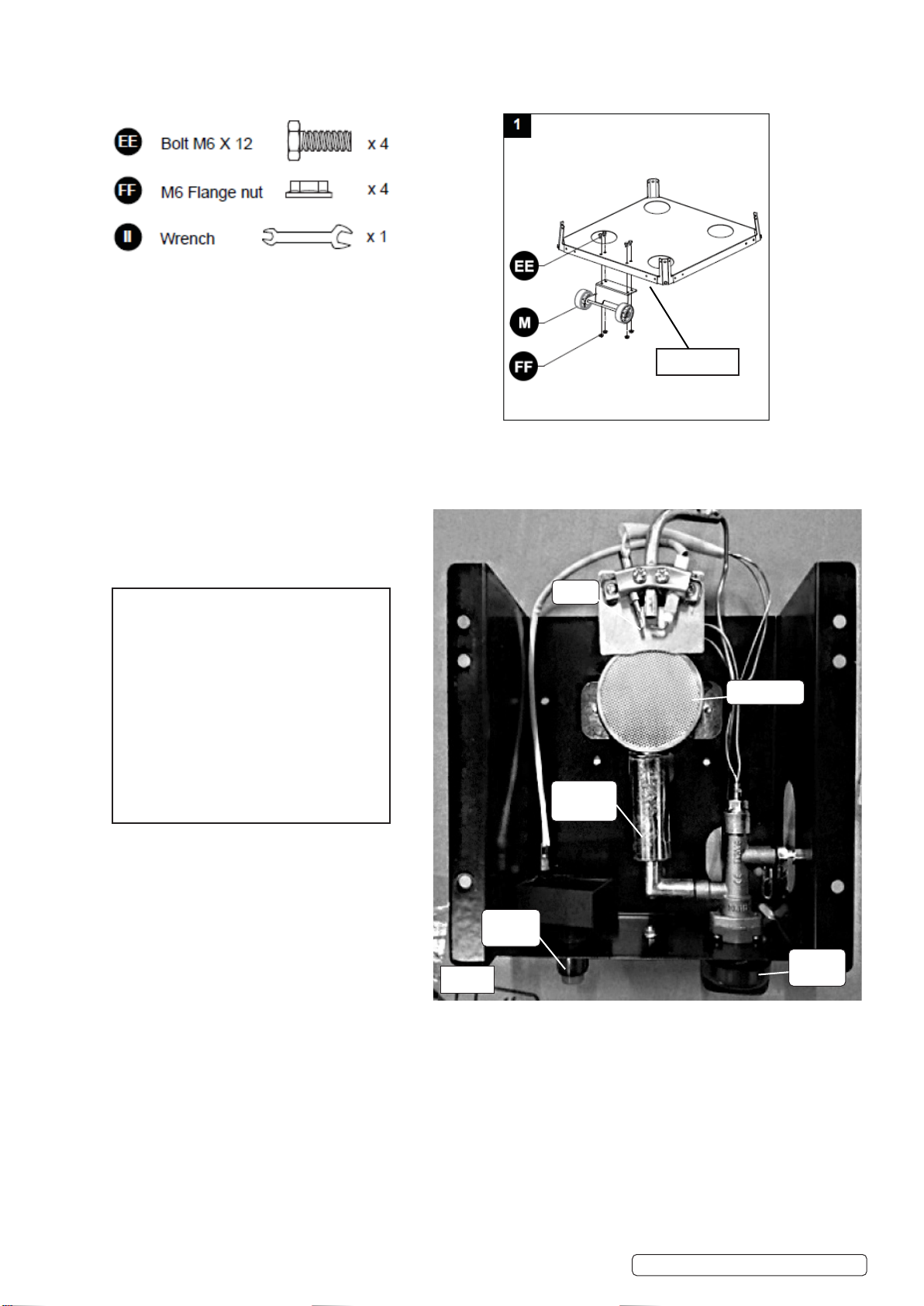
5.6. DIAGRAM 1Fixthewheelassemblytothebottomplate,use4pcsboltM6X12and4pcsangenutM6.
5.7. CONTROL UNIT (CHECK)
5.8. Oncethegashosehasbeensafelyattachedtothecontrolunit(K)andgasbottleregulatorthecontrolunitassemblycannowbe
installedontothemiddleplate(J).Beforemovingontounitassemblycheckforthecorrectorientationofallcomponents(Fig.5).
Original Language Version DG5,DG6Issue:6(3,4,5)30/06/2021
Back of unit
Igniter
Ignition
switch
Control
knob
Burner Mesh
Mixing
chamber
NOTE:
Ensure the control unit assembly (K)
is installed with the controls facing
the front of the unit.
Ensure all components appear as
in (Fig. 5) within the control unit,
if any components are missing or
dislodged. *STOP* Contact the
supplier for assistance.
Fig.5
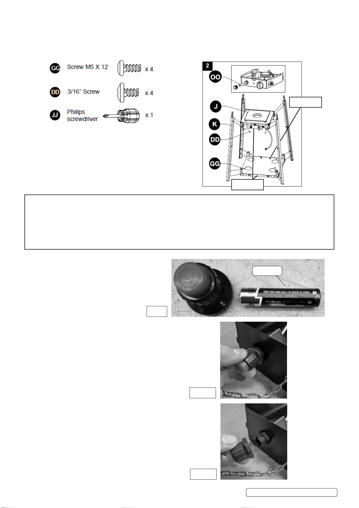
5.9. DIAGRAM 2Unscrewtheswitchbutton,tbattery,rettheswitchbutton.
5.10. Insertthepinsofthebasetotheholesoflowersupport,presstosecurethepins.Use4xM5X12screwstosecurethelowersupport
andbase.
5.11. Insertthepinsofthecontrolboxassemblytotheholesofuppersupport,presstosecurethepins.Use4x3/16”screwstosecurethe
uppersupportandcontrolboxassembly.
NOTE:
It is vital at this stage to ensure that the bottom plate (N) and the middle plate (J) are assembled correctly.
The wheels on the bottom plate (N) are the back of the unit and the magnetic catches on the middle plate
(J) for the door are on the front of the unit, these parts must be on OPPOSITE sides of the unit. This must be
correct at this stage to ensure the unit operates correctly.
AAA Battery
TheignitionswitchmusthaveaAAAbattery
insertedintoit,Unscrewthecollaroftheswitchand
insertabatterythenrescrewtheswitchheadinto
place(Fig.6).
Unscrewthebuttoncollaruntilitcomesawayfromtheunit.(Fig.6.1).
Fig.6.1
SlideinaAAAbatteryandre-screwthebuttonintoposition.(Fig.6.2).
Fig.6.2
Front of unit.
Back of unit.
Fig.6
Original Language Version DG5,DG6Issue:6(3,4,5)30/06/2021
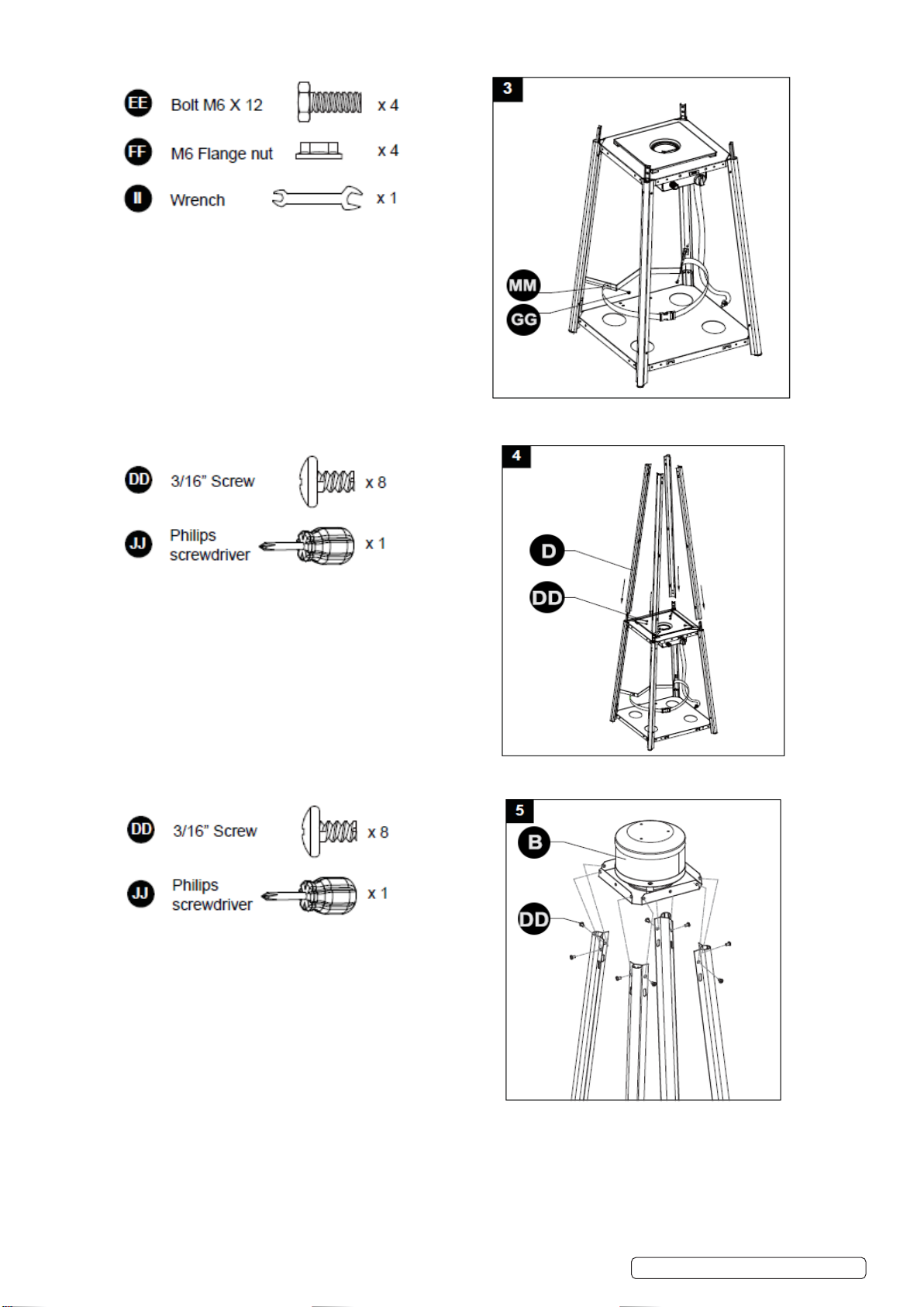
5.12. DIAGRAM 3Assemblethegascylinderbelt.Fixthebelttothetwolowersupportsbehindthefrontdoor,use2xM5x12screws.
5.13. DIAGRAM 4 Assemblethemiddlesupport.Insertthe4pcsuppersupport.Securewith8x3/16”screws.
5.14. DIAGRAM 5Fixtheamescreentotheuppersupports.Use8x3/16”screws.
Original Language Version DG5,DG6Issue:6(3,4,5)30/06/2021

5.15. DIAGRAM 6Fixthereectorontotheamescreen.Screwthe3studsontothetopoftheamescreen.
Place3xØ6mmwashersontopofthestud.Placethereectorontothestudandsecurewith3xØ6mmwashersand3xwingnuts.
5.16. DIAGRAM 7 Carefullyinstalltheglasstubebyliftingitupandinsertingthroughthecentreholeintheupperplate.Ensuretheblack
siliconeringisattachedtotheloweredgeoftheglasstubeasillustrated.Slidetheglasstubethroughtheholeofthelowerplatecover
andontothemiddleplate.Checkandensurethattheglasstubeispositionedproperlyandiscompletelycoveringthecentreholeof
themiddleplate.
5.17. DIAGRAM 8 Assembletheprotectiveguard.Fittheprotectiveguards,pushthehooksintotheslotsintheuppersupportsandletthem
slidedowntosecure.Fixthe4bracketstoretaintheminplace.
Original Language Version DG5,DG6Issue:6(3,4,5)30/06/2021
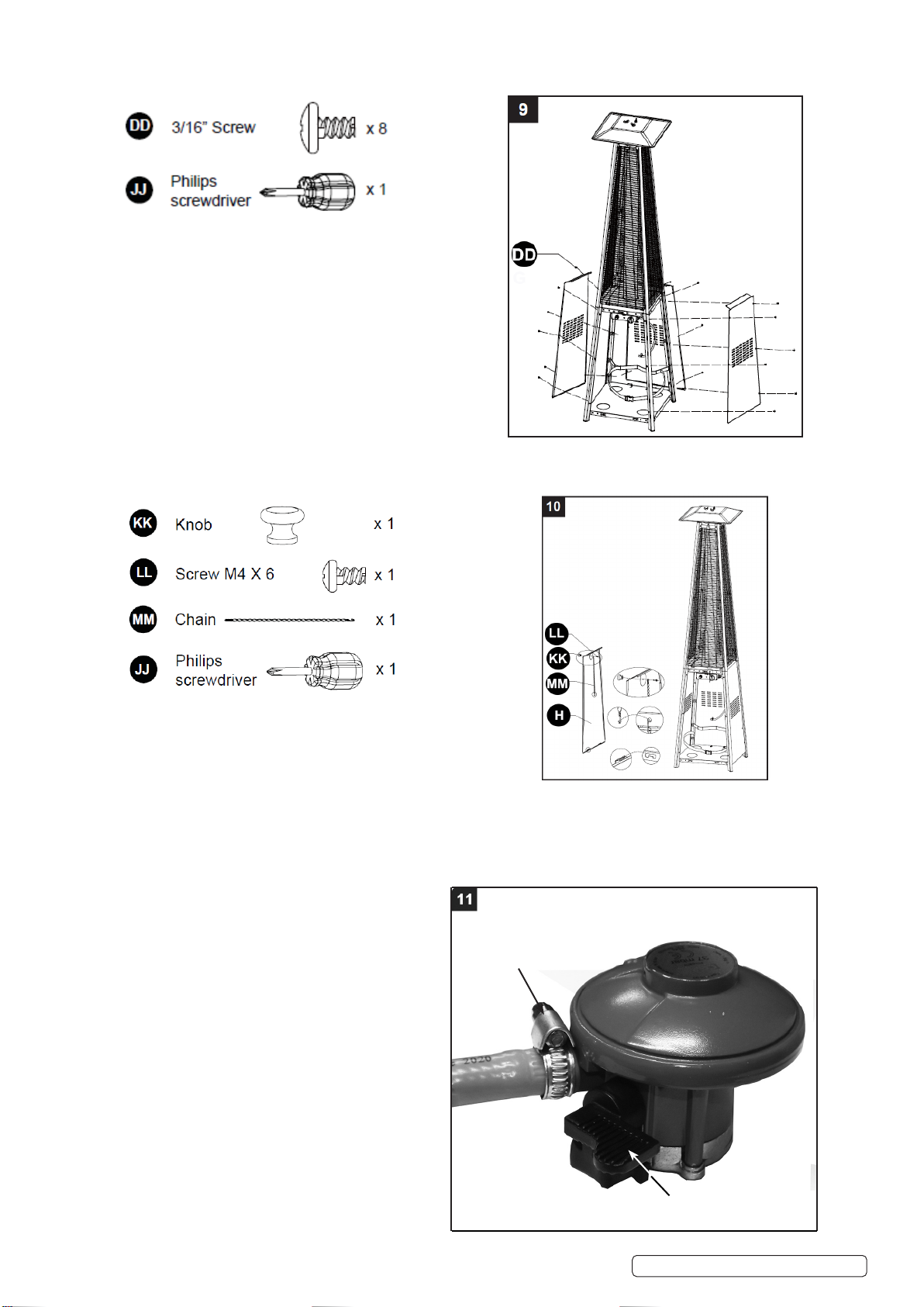
5.18. DIAGRAM 9 Attachthe3sidepanelstotheheaterusing18x3/16”screw.Note: DO NOTtthefrontpanelatthisstage.
5.19. DIAGRAM 10
Fitknobtodoorandchaintotherearofthedoor.UseM4x6screw.Fixtheotherendofchainontotheholeonthecontrolbox
assembly.Locatethehooksonthebottomedgeofthedoorintothecutoutsonthebottomplateandpushthedoorintoposition.
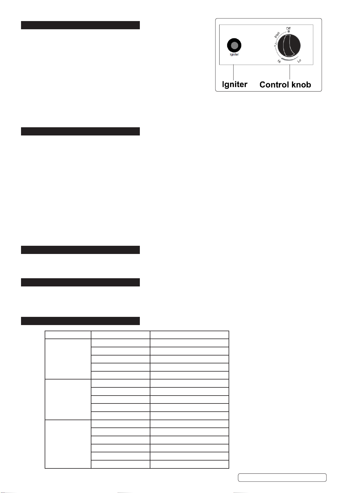
5.20. DIAGRAM 11 (REGULATORARRANGEMENT)
Checkthattheregulatorisclosedandthetapisintheopositioni.e.horizontal.Removethesealcapfromthe
cylinderautomaticvalveandconnectregulatortothegascylinderbypushingregulatordownverticallyandrmlyontothecylinder
valve.Conrmfullandsecureengagementofregulatortothecylindervalve.
NOTE: Ensure you leak test this joint as directed in
Section 6 after assembly is complete and when you
rst connect the gas bottle.
WARNING! Ensure full engagement of hose to regulator
andcontrolunit.
WARNING!Checkthatthewormdriveclipsatbothends
ofthegashosearefullytightened.
WARNING!Arrangethegashoseandregulatortoensure
thehosedoesnotcomeintocontactwithanyhigh
temperaturesurfacesasitmaymeltandcauseare.
Afterthecylinderisplacedinsidetheheater,tightly
securethecylinderwiththebelt.
NOTE:Seesection6forLeakCheckprocedure.
Original Language Version DG5,DG6Issue:6(3,4,5)30/06/2021
Ensuregashoseisfully
engagedtostemandthe
wormdriveisfully
tightened.
TapinOffposition
6. LEAK CHECK
WARNING!Aleaktestmustbeperformed:
-beforerstuse
-annually
-eachtimeacylinderischanged
-orifanypartofthegassystemhasbeenreplaced.
WARNING!Neveruseanopenametocheckforgas
leaks.Makesuretherearenosparksoropenamesin
theareawhilstcheckingforleaks.
6.1. Removeallsourcesofignition.
6.2. Turnallburnercontrolstotheoposition.Turngasregulatoron.Brushahalf
andhalfsolutionofliquidsoapandwaterontoalljointsandconnections(regulator,hose,manifoldsandvalves.)
6.3. Bubbleswillindicateagasleak.Tightenorloosentheloosejointorhavethepartreplacedwitharecommendedgenuinepart.Have
thepatioheaterinspectedbyacertiedgasinstaller.
6.4. IftheleakcannotbestoppedSHUT OFF THE GAS SUPPLY IMMEDIATELY,disconnectitandhavethepatioheaterinspectedbya
certiedgasinstallerordealer.DO NOTusethepatioheateruntiltheleakhasbeencorrected.
7. OPERATION
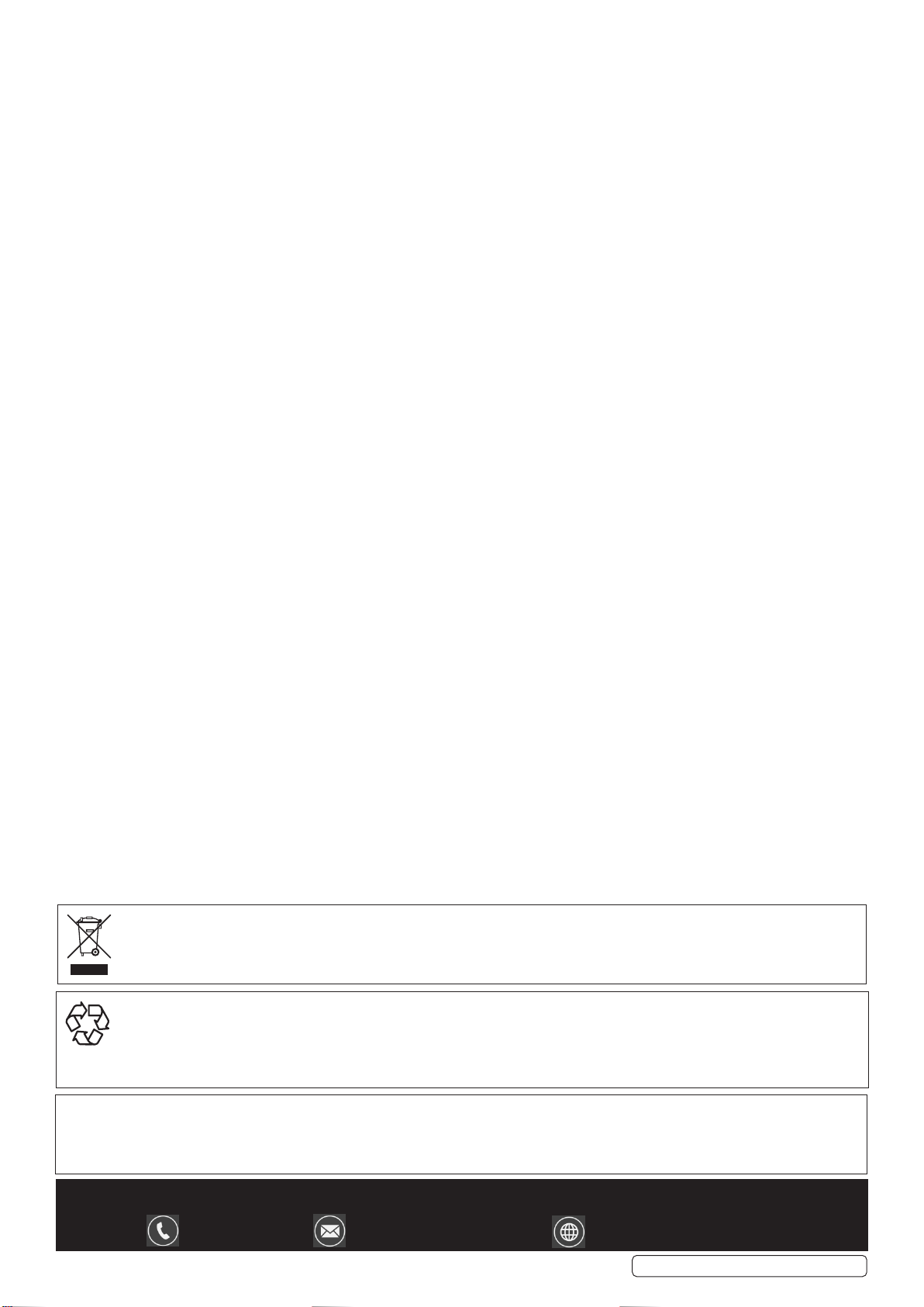
7.1. TO TURN ON THE HEATER
7.1.1. Openthegasregulatorvalvefully.
7.1.2. PressandturnthevariablecontrolknobtothePILOTposition(anticlockwise90°).
7.1.3. Pressdownthecontrolknobfor60seconds.Whilstholdingdownthecontrolknob
presstheigniterbuttonseveraltimesuntilthepilotamelights.Releasethe
controlknobafterthepilotamelights.
Note:Ifanewcylinderhasbeenttedallowatleastoneminuteforairinthegas
pipelinetopurgeoutthroughthepilothole.
Whenlightingthepilotame makesurethatthecontrolknobispresseddown
continuously,whilstpressingtheigniterbutton.Thecontrolknobcanbereleased
afterthepilotamelights.Ifthepilotamedoesnotlightrepeatstep7.1.3.
7.1.4. Afterthepilotamelightsturnthecontrolknobtoitsmaximumpositionandleaveit
therefor5minutesormorebeforeturningthecontrolknobtothedesiredtemperatureposition.
WARNING!Checkthattheglassis NOTbrokenbeforeoperation.
7.2. TO TURN OFF THE HEATER
7.2.1. TurnthecontrolvalvetothePILOTposition.
7.2.2. PressandturnthecontrolknobtotheOFFposition.Turnothegascylindercompletely.
8. STORAGE
8.1. Alwaysclosethegasvalveatthegascylinderandremovetheregulatorfromthecylinder.
8.2. Checkthegasvalvefordamage.Ifdamageissuspectedhaveitinspectedbyagasdealer.
8.3. Storeinachildproof,dryareawithadequateairventilation.Neverstorealiquidgascylinderinacellarorbelowgroundlevel.
9. MAINTENANCE
9.1. CLEANING
9.1.1. Wipesurfaceswithamoist,softrag.DO NOTcleanwithaggressiveorcombustiblecleaners.
9.1.2. Removedebrisfromtheburnertokeepitsafeforuse.
9.1.3. Covertheheaterwithaprotectivecoverwhentheheaterisnotinuse,(Sealeymodelno:DG7notsupplied).
10. TROUBLESHOOTING
Original Language Version DG5,DG6Issue:6(3,4,5)30/06/2021
Problem Probable cause Solution
Pilot will not light Gasvalvemaybeoff Turngasvalveon
Cylinderempty Renewcylinder
Openingblocked Cleanorreplaceopening
Airinsupplysystem Purge air from lines
Loose connections Checkallfittings
Pilotwillnotstayon Debrisaroundpilot Cleardirtyarea
Loose connections Tighten connections
Thermocouplebad Replacethermocouple
Gasleakinline Checkconnections
Lackoffuelpressure Cylindernearlyempty,refillcylinder
Burner will not light Pressure is low Cylindernearlyempty,refillcylinder
Openingblocked Removeandclean
Control not on Turnvalvetoon
Thermocouplebad Replacethermocouple
Pilotlightassemblybent Placepilotlightproperly
Not in correct location Positionproperlyandretry
WEEE REGULATIONS
DisposeofthisproductattheendofitsworkinglifeincompliancewiththeEUDirectiveonWasteElectricalandElectronicEquipment
(WEEE).Whentheproductisnolongerrequired,itmustbedisposedofinanenvironmentallyprotectiveway.Contactyourlocalsolid
wasteauthorityforrecyclinginformation.
Dellonda Ltd., KempsonWay,SuffolkBusinessPark,BuryStEdmunds,Suffolk.IP327AR
01284757575 [email protected]www.dellonda.co.uk
ENVIRONMENT PROTECTION
Recycleunwantedmaterialsinsteadofdisposingofthemaswaste.Alltools,accessoriesandpackagingshouldbesorted,takento
arecyclingcentreanddisposedofinamannerwhichiscompatiblewiththeenvironment.Whentheproductbecomescompletely
unserviceableandrequiresdisposal,drainanyfluids(ifapplicable)intoapprovedcontainersanddisposeoftheproductandfluids
accordingtolocalregulations.
Note:Itisourpolicytocontinuallyimproveproductsandassuchwereservetherighttoalterdata,specificationsandcomponentpartswithoutprior
notice.
Important:NoLiabilityisacceptedforincorrectuseofthisproduct.
Warranty:Guaranteeis12monthsfrompurchasedate,proofofwhichisrequiredforanyclaim.
Original Language Version DG5,DG6Issue:6(3,4,5)30/06/2021
This manual suits for next models
1
Table of contents
Other dellonda Heater manuals


