DeLOCK 12951 User manual

IoT LoRa Radio Module 868 MHz 20 dB TTL (3.3 V)
User manual
Product-No:12951
User manual no:12951-a
www.delock.com

-1-
1. Specification and parameter
1.1 Limit parameter
Main parameter
Performance
Notes
Min.
Max.
Power supply
(
V
)
0 5.2
Voltage over 5.2V will cause permanent
damage to module
Blocking power
(
dBm
)
- -10
Chances of burn is slim when modules
are used in short distance
Operating temperature
(℃)
-40
85
-
1.2 Operating parameter
Main parameter
Performan
ce
Remark
Min
Typ.
Max.
Operating voltage
(
V
)
3.3
5.0
5.2
≥5.0 V ensures output power
Communication level
(
V
)
-3.3 -
For 5V TTL, it may be at risk of
burning down
Operating temperature
(℃)
-40
-
85
Industrial design
Operating frequency
(
MHz
)
862
-868
893
Support ISM band
Power
consumptio
n
Transmitting current [mA]
-
106
-
Instant power consumption
Receiving current [mA]
-
15
-
-
Turn-off current [μA]
-4 -Software is shut down
Max Tx power
(
dBm
)
19.2
-
20.0
-
Receiving sensitivity
(
dBm
)
-144
-146
-147
Air data rate is 2.4kbps
Air data rate
(
bps
)
0.3k
2.4k
19.2k
Controlled via user’s programming
Main parameter
Description
Remark
Distance for reference 3000m
Test condition
:
clear and open area, antenna gain: 5dBi
,
antenna height: 2.5m,air data rate: 2.4kbps
TX length 58 Btye
Maximum capacity of single package, automatic
subcontracting after exceeding
Buffer
512 Btye
-
Modulation
LoRa™
-

-2-
Communication interface
TTL
@3.3V
Package
DIP
-
Connector
2.54mm
-
Size
21 * 36mm
-
Antenna
SMA-K
50 ohm impedance
2. Size and pin definition
No.
Name
Direction
Function
1 M0
Input
(weak pull-up)
Work with M1 to decide 4 working modes of module (not suspended, if
not used, could be grounded).

-3-
2 M1
Input
(weak pull-up)
Work with M0 to decide 4 working modes of module (not suspended, if
not used, could be grounded).
3 RXD Input
TTL UART inputs, connects to external (MCU, PC) TXD output pin. Can
be configured as open-drain or pull-up input.
4
TXD
Output
TTL UART outputs, connects to external RXD (MCU, PC) input pin. Can
be configured as open-drain or push-pull output
5 AUX Output
To indicate module ’ s working status & wakes up the external MCU.
During the procedure of self-check initialization, the pin outputs low
level. Can be configured as push-pull output (suspending is allowed).
6
VCC
Input
Power supply
:
2.3~ 5.2V DC
7
GND
Input
Ground
8
Fixed orifice
-
Fixed orifice
9
Fixed orifice
-
Fixed orifice
10
Fixed orifice
-
Fixed orifice
3. Connect to MCU
No.
Description(STM8L MCU)
1 The UART module is TTL level.
2 For some MCU works at 5VDC, it may need to add 4-10K pull-up resistor for the TXD & AUX pin.

-4-
4. Function description
4.1 Fixed transmission
4.2 Broadcasting transmission
4.3 Broadcasting address
For example: Set the address of module A as 0xFFFF or 0x0000, and the channel as 0x04;

-5-
When module is the transmitter (transparent transmission), all modules under channel 0x04 will receive the data, the
purpose of broadcast is realized.
5.4 Monitor address
For example: Set the address of module A as 0xFFFF or 0x0000, and the channel as 0x04;
When module A is the receiver, it can receive the data sent from all modules under channel 0x04, the purpose of
monitor is realized.
4.5 Reset
When the module is powered, AUX outputs low level immediately, conducts hardware self-check and sets the
operating mode based on user’s parameters. During the process, the AUX remains low level. After the process
completed, the AUX outputs high level and starts to work as per the operating mode combined by M1 and M0.
Therefore, users need to wait the AUX rising edge as the start of module’s normal work.
4.6 AUX description
AUX Pin can be used as indication for wireless send & receive buffer and self-check.
It can indicate whether there are data that are not sent yet via wireless way, or whether all wireless data has been
sent through UART, or whether the module is still in the process of self-check initialization.
4.6.1 Indication of UART output
To wake up external MCU
4.6.2 Indication of wireless transmitting
Buffer (empty): the internal 512 bytes data in the buffer are written to the RFIC (Auto sub-packaging).

-6-
When AUX=1, the user can input data less than 512 bytes continuously without overflow. Buffer (not empty): when
AUX=0, the internal 512 bytes data in the buffer have not been written to the RFIC completely. If the user starts to
transmit data at this circumstance, it may cause overtime when the module is waiting for the user data, or
transmitting wireless sub package.
When AUX = 1, it does not mean that all the UART data of the module have been transmitted already, perhaps the
last packet of data is still in transmission.
4.6.3 Configuration procedure of module
Only happened when power-on resetting or exiting sleep mode
4.6.4 Notes for AUX
No. Description
1
For function 1 & function 2 mentioned above, the priority should be given to the one with low level output, which means if it
meets each of any low level output condition, AUX outputs low level, if none of the low level condition is met, AUX outputs
high level.
2
When AUX outputs low level, it means the module is busy & cannot conduct operating mode checking. Within 1ms since
AUX outputs high level, the mode switch will be completed.

-7-
3
After switching to new operating mode, it will not work in the new mode immediately until AUX rising edge lasts for 2ms .
If AUX stays on the high level, the operating mode switch can be effected immediately.
4
When the user switches to other operating modes from mode 3 (sleep mode) or it’s still in reset process, the module will reset
user parameters, during which AUX outputs low level.
5. Operating mode
There are four operating modes, which are set by M1 and M0, the details are as follows:
Mode
(
0-3
)
M0
M1
Mode introduction
Remark
0 Normal
0
UART and wireless channel are open, transparent
transmission is on
The receiver must work in mode 0
or mode 1
1 wake up
1
0
UART and wireless channel are open, the only
difference with mode 0 is that before transmitting data,
increasing the wake up code automatically, so that it can
awake the receiver under mode 3.
The receiver could be 0,1 or 2
2 power saving
0
1
UART close, wireless is under air-awaken mode, after
receiving data, UART open and send data.
transmitter must be mode 1,
unable to transmit in this mode.
3 sleep
1
1
sleep mode, receiving parameter setting command is
available.
more details on
parameter specification.
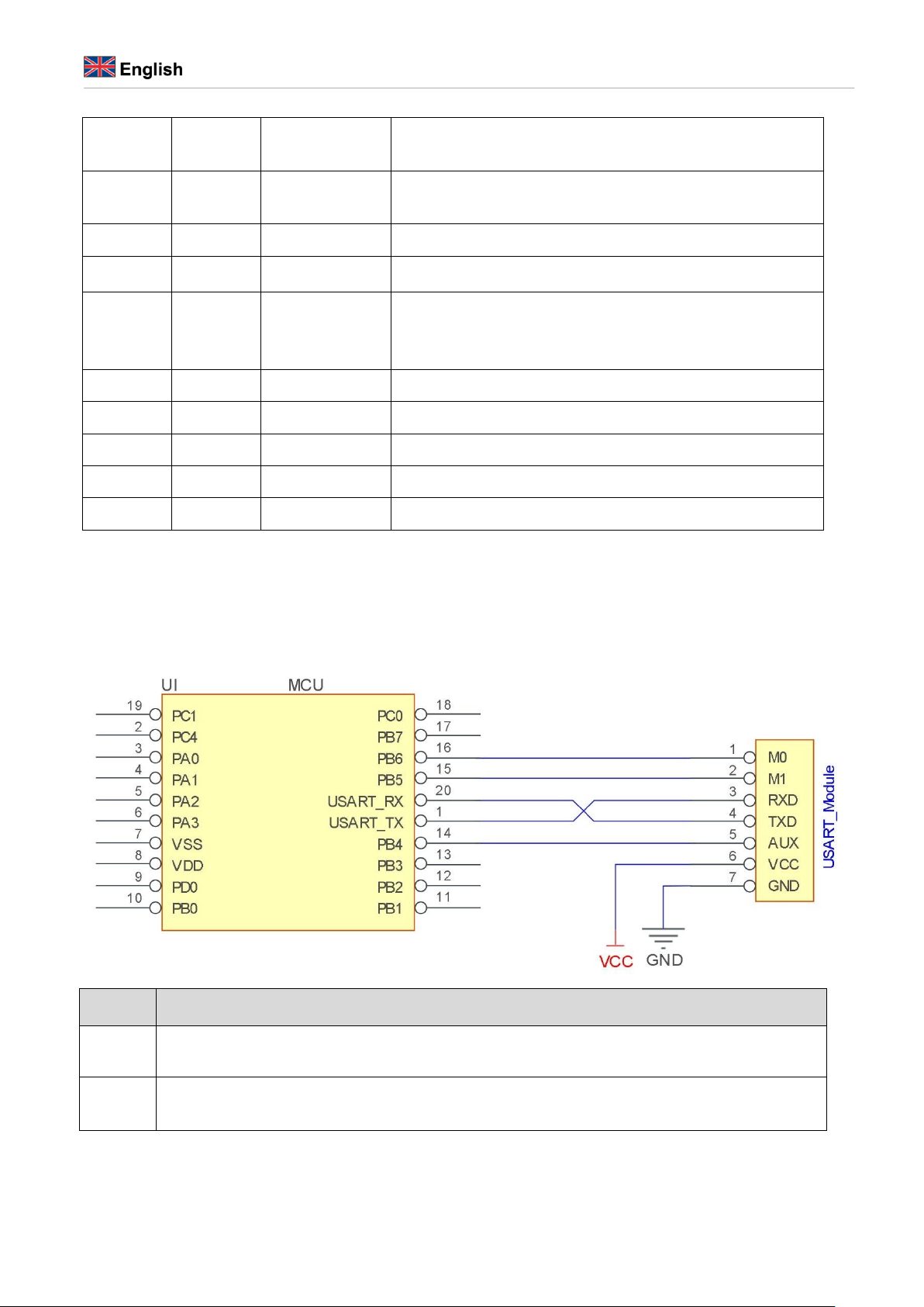
5.1 Mode switch
The user can decide the operating mode by the combination of M1 and M0. The two GPIO of MCU can be used to
switch mode. After modifying M1 or M0, it will start to work in new mode 1ms later if the module is free. If there
are any serial data that are yet to finish wireless transmitting, it will start to work in new mode after the UART
transmitting finished. After the module receives the wireless data & transmits the data through serial port, it will
start to work in new mode after the transmitting finished. Therefore, the mode-switch is only valid when AUX
outputs 1, otherwise it will delay.
For example, in mode 0 or mode 1, if the user inputs massive data consecutively and switches operating mode at the
same time, the mode-switch operation is invalid. New mode checking can only be started after all the user’s data
process completed. It is recommended to check AUX pin out status and wait 2ms after AUX outputs high level
before switching the mode.
If the module switches from other modes to stand-by mode, it will work in stand-by mode only after all the
remained data process completed. The feature can be used to save power consumption. For example, when the
transmitter works in mode 0, after the external MCU transmits data “12345”, it can switch to sleep mode
immediately without waiting the rising edge of the AUX pin, also the user’s main MCU will go dormancy
immediately. Then the module will transmit all the data through wireless transmission & go dormancy 1ms later
automatically, which reduces MCU working time & save power.
Likewise, this feature can be used in any mode-switch. The module will start to work in new mode within 1ms after
completing present mode task, which enables the user to omit the procedure of AUX inquiry and switch mode

-8-
swiftly. For example, when switching from transmitting mode to receiving mode, the user MCU can go dormancy
before mode-switch, using external interrupt function to get AUX change so that the mode-switch can be realized.
This operation is very flexible and efficient. It is totally designed on the basis of the user MCU’s convenience, at the
same time the work load and power consumption of the whole system have been reduced and the efficiency of
whole system is largely improved.
5.2 Normal mode (mode 0)
When M1 = 0 & M0 = 0, module works in mode 0
Transmitting
The module can receive the user data via serial port, and transmit wireless data package of 58 bytes. When the data
inputted by user is up to 58 byte, the module will start wireless transmission. During which the user can input data
continuously for transmission.
When the required transmission bytes are less than 58 bytes, the module will wait 3-byte time and treat it as data
termination unless continuous data inputted by user. Then the module will transmit all the data through wireless
channel.
When the module receives the first data packet from user, the AUX outputs low level.
After all the data are transmitted into RF chip and transmission start , AUX outputs high level.
At this time, it means that the last wireless data package transmission is started, which enables the user to input
another 512 bytes continuously. The data package transmitted from the module working in mode 0 can only be
received by the module working in mode 0 or 1.
Receiving
The wireless receiving function of the module is on, the data packet transmitted from the module working in mode 0
& mode 1 can be received.
After the data packet is received, the AUX outputs low level, 5ms later the module starts to transmit wireless data
through serial port TXD pin.
After all the wireless data have been transmitted via serial port, the AUX outputs high level.
5.3 Wake-up mode (mode 1)
When M1 = 0 & M0 = 1, module works in mode 1
Transmitting
The condition of data packet transmission & AUX function is the same as mode 0. The only difference is that
the module will add preamble code before each data packet automatically. The preamble code length depends
on the wake-up time set in the user parameters. The purpose of the preamble code is waking up the receiving
module works in mode 2. Therefore, the data package transmitted from mode 1 can be received by mode 0,
mode1 and mode 2.
Receiving The same as that in mode 0.
5.4 Power-saving mode (mode 2)
When M1 = 1 & M0 = 0, module works in mode 2
Transmitting UART is closed, the module cannot receive any serial port data from outside MCU.
Hence the function of wireless transmission is not available for the module working in this mode.

-9-
Receiving
In mode 2, it is required the data transmitter works in mode 1.
The wireless module monitors the preamble code at regular time.
Once it gets the preamble code, it will remain as receiving status and waiting for the completion of receiving the
entire valid data package.
Then the AUX outputs low level, 5ms later the serial port is open to transmit received wireless data through
TXD. Finally, AUX outputs high level after process completed.
The wireless module stays in “power-saving – monitoring” working status (polling).
By setting different wake-up time, the module will have different receiving response delay (2s in maximum) and
average power consumption (30uA in minimum).
The user needs to achieve a balance between communication delay time & average power consumption.
5.5 Sleep mode (mode 3)
When M1=1, M0=1, module works in mode 3
Transmitting
N/A
Receiving
N/A
Parameter setting
This mode can be used for parameter setting. It uses serial port 9600 & 8N1 to set module working parameters
through specific instruction format. (pls refer to parameters setting for details)
Notes
When the mode changes from stand-by mode to others, the module will reset its parameters, during which the
AUX keeps low level and then outputs high level after reset completed. It is recommended to check the AUX
rising edge for user.
6. Command format
In sleep mode(Mode 3:M1=1, M0=1), it supports below instructions on list.
(Only support 9600 and 8N1 format when setting)
No. Instruction format Illustration
1
C0+working
parameters
C0 + 5 bytes working parameters are sent in hexadecimal format. 6 bytes in total and
must be sent in succession, ( Save the parameters when power-down ).
2 C1+C1+C1
( Save the parameters when power-down )
3
C2+working
parameters
Three C1 are sent in hexadecimal format. The module returns the saved parameters
and must be sent in succession.
4 C3+C3+C3
C2 + 5 bytes working parameters are sent in hexadecimal format. 6 bytes in total and
must be sent in succession. (Do not save the parameters when power-down)
5 C4+C4+C4
Three C3 are sent in hexadecimal format. The module returns the version
information and they must be sent in succession.

-10-
6.1 Default parameters
type
Default parameter values
::
C0 00 00 1A 17 44
Model Frequency Address Channel Air data rate Baud rate Parity
Transmitting power
E32-433T30D 433MHz 0x0000 0x17 2.4kbps 9600 8N1 1W
6.2 Reading operating parameters
Instruction format
Description
C1+C1+C1
In sleep mode
(
M0=1
,
M1=1
),
User gives the module instruction (HEX format): C1 C1 C1, Module
returns the present configuration parameters.
For example, C0 00 00 1A 17 44.
6.3 Reading version number
Instruction format
Description
C3+C3+C3
In sleep mode
(
M0=1
,
M1=1
)
,User gives the module instruction (HEX format): C3 C3
C3,Module returns its present version number, for example C3 32 xx yy. the second bytes means
frequency. 32 here means the frequency is 433MHZ, 38 means frequency is 470MHz, 45 means
frequency is; 868MHz, 44 means the frequency is 915 MHz, 46 means the frequency is 170MHz;
xx is the version number and yy refers to the other module features.
6.4 Reset command
Instruction format
Description
C4+C4+C4
In sleep mode
(
M0=1
,
M1=1
)
,
User gives the module instruction (HEX format): C4 C4 C4, the module resets for one time. During
the reset process, the module will conduct self-
check, AUX outputs low level. After reset
completing, the AUX outputs high level, then the module starts to work regularly which the
working mode can be switched or be given another instruction.
6.5 Parameter setting command
No. Item Description Remark
0 HEAD
Fix 0xC0 or 0xC2, it means this frame data is control command
Must be 0xC0 or 0xC2
C0: Save the parameters
when
power-down
C2: Do not save the parameters when
power-down

-11-
1 ADDH
High address byte of module
(the default 00H)
00H-FFH
2 ADDL
Low address byte of module
(the default 00H)
00H-FFH
3 SPED
7
6
UART parity bit
UART mode can be different between
communication parties
0
0
8N1 (default)
0
1
8O1
1
0
8 E1
1
1
8N1 (equal to 00)
5
4
3
TTL UART baud rate(bps)
UART baud rate can be different
between communication parties
The UART baud rate has nothing to do
with wireless transmission parameters
& won’t affect the wireless transmit /
receive features.
0
0
0
1200
0
0
1
2400
0
1
0
4800
0
1
1
9600 (default)
1
0
0
19200
1
0
1
38400
1
1
0
57600
1
1
1
115200
2
1
0
Air data rate(bps)
The lower the air data rate, the longer the
transmitting distance, better anti-
interference performance and longer
transmitting time
The air data rate must keep the same for
both communication parties.
0
0
0
0.3k
0
0
1
1.2k
0
1
0
2.4k (default)
0
1
1
4.8k
1
0
0
9.6k
1
0
1
19.2k
1
1
0
19.2k (same to 101)
1
1
1
19.2k (same to 101)
General Specifications
Except for E32 (400T20S)
4 CHAN
7
6
5
reserved
Write 0
Communication channel
00H-1FH, correspond to

-12-
4-0, channel (410M + CHAN*1M), default 17H(433MHz)
410~441MHz
5 OPTION
7
Fixed transmission enabling bit(similar to MODBUS)
In fixed transmission mode, the first three
bytes of each user's data frame can be
used as high/low address and channel.
The module changes its address and
channel when transmit. And it will revert
to
original setting after complete the
process.
0
Transparent transmission mode
1 Fixed transmission mode
6
IO drive mode (default 1)
This bit is used to the module internal pull-
up resistor. It also increases the level’s
adaptability in case of open drain. But in
some cases, it may need external pull-up
resistor.
1
TXD and AUX push-pull outputs, RXD pull-up inputs
0 TXD、AUX open-collector outputs, RXD open-collector
inputs
5
4
3
wireless wake-up time
The transmit & receive module work in
mode 0, whose delay time is invalid &
can be arbitrary value.
The transmitter works in mode 1 can
0
0
0
250ms (default)
0
0
1
500ms
0
1
0
750ms
0
1
1
1000ms
transmit the preamble code of the
corresponding time continuously.
When the receiver works in mode 2, the
time means the monitor interval time
(wireless wake-up). Only the data from
transmitter that works in mode 1 can be
received.
1
0
0
1250ms
1
0
1
1500ms
1
1
0
1750ms
1 1 1 2000ms
2
FEC switch
After turn off FEC, the actual data
transmission rate increases while
anti-interference ability decreases. Also
the transmission distance is relatively
short.
Both communication parties must keep
on the same pages about turn-on or turn-
off FEC.
0
Turn off FEC
1 Turn on FEC (default)
1
0
Transmission power (approximation)
The external power must make sure the
ability of current output more than 1A and
ensure the power supply ripple within 100mV.
Low power transmission is not
recommended due to its low power supply
0
0
30dBm (default)
0
1
27dBm
1
0
24dBm

-13-
1 1 21dBm
efficiency.
For example: The meaning of No.3 "SPED" byte:
The binary bit of the byte
7
6
5
4
3
2
1
0
Configures by user
0
0
0
1
1
0
1
0
Meaning
UART parity bit 8N1
UART baud rate is 9600
Air data rate is 2.4k
Corresponding hexadecimal
1
A
Support Delock
If you have further questions, please contact our customer support support@delock.de
You can find current product information on our homepage: www.delock.com
Final clause
Information and data contained in this manual are subject to change without notice in advance. Errors and misprints excepted.
Copyright
No part of this user's manual may be reproduced, or transmitted for any purpose, regardless in which way or by which means, electronically or
mechanically, without explicit written approval of Delock.
Edition: 05/2019

Declaration of conformity
Products with a CE symbol fulll the RED directive (2014/53/EU) and RoHS directive
(2011/65/EU+2015/863), which were released by the EU-comission.
The declaration of conformity can be downloaded here: http://www.delock.de/service/conformity
WEEE-notice
The WEEE (Waste Electrical and Electronic Equipment)-directive, which became effective as
European law on February 13th 2003, resulted in an all out change in the disposal of disused
electro devices. The primarily purpose of this directive is the avoidance of electrical waste (WEEE)
and at the same time the support of recycling and other forms of recycling in order to reduce
waste. The WEEE-logo on the device and the package indicates that the device should not be
disposed in the normal household garbage. You are responsible for taking the disused electrical
and electronical devices to a respective collecting point. A separated collection and reasonable
recycling of your electrical waste helps handling the natural resources more economical.
Furthermore recycling of electrical waste is a contribution to keep the environment and thus also
the health of men. Further information about disposal of electrical and electronical waste, recycling
and the collection points are available in local organizations, waste management enterprises, in
specialized trade and the producer of the device.
EU Import: Tragant Handels- und Beteiligungs GmbH
Beeskowdamm 13/15, 14167 Berlin, Germany
Table of contents
Other DeLOCK Control Unit manuals