DeLonghi DE 302 IB-1 Installation guide

DE’LONGHI
COOKING
INSTALLATION and SERVICE INSTRUCTIONS
USE and CARE INSTRUCTIONS
DE 302 IB-1
INDUCTION BUILT-IN COOKTOPS
distributed by
DeLonghi Australia Pty Ltd
DeLonghi New Zealand Ltd

2
Dear Customer,
Thank you for having purchased and given your preference
to our product.
The safety precautions and recommendations reported
below are for your own safety and that of others. They
will also provide a means by which to make full use of the
features offered by your appliance.
Please keep this booklet in a safe place. It may be useful
in future, either to yourself or to others in the event that
doubts should arise relating to its operation.
This appliance must be used only for the task it
has explicitly been designed for, that is for cooking
foodstuffs. Any other form of usage is to be considered
as inappropriate and therefore dangerous.
The manufacturer declines all responsibility in the
event of damage caused by improper, incorrect or
illogical use of the appliance or be faulty installation.
PRODUCT LABEL
This appliance has been designed and constructed in accordance with the following codes
and specications:
AS/NZS 60335.1 General Requirements for Domestic electrical appliances
AS/NZS 60335.2.6 Particular Requirements for Domestic electrical cooking appliances
AS/NZS CISPR 14.1 Electromagnetic Compatibility Requirements.

3
IMPORTANT SAFETY PRECAUTIONS AND RECOMMENDATIONS
IMPORTANT: This appliance is designed and manufactured
solely for the cooking of domestic (household) food and is
not suitable for any non domestic application and therefore
should not be used in a commercial environment.
The appliance guarantee will be void if the appliance is used
within a non domestic environment i.e. a semi commercial,
commercial or communal environment.
Read the instructions carefully before installing and using
the appliance.
■After having unpacked the appliance, check to ensure that it is not
damaged.
In case of doubt, do not use it and consult your supplier or a
professionally qualied technician.
■Packing elements (i.e. plastic bags, polystyrene foam, nails, packing
straps, etc.) should not be left around within easy reach of children,
as these may cause serious injuries.
■ Some appliances are supplied with a protective lm on steel and
aluminium parts. This lm must be removed before using the
appliance.
■ IMPORTANT: The use of suitable protective clothing/gloves is
recommended when handling or cleaning this appliance.
■Do not attempt to modify the technical characteristics of the
appliance as this may become dangerous to use. The manufacturer
declines all responsibility for any inconvenience resulting from the
inobservance of this condition.
■Do not operate your appliance by means of an external timer or
separate remote-control system.
■Do not carry out cleaning or maintenance operations on the
appliance without having previously disconnected it from the electric
power supply.
■Do not use a steam cleaner because the moisture can get into the
appliance thus make it unsafe.
■Do not touch the appliance with wet or damp hands (or feet).
■Do not use the appliance whilst in barefoot.

4
■If you should decide not to use this appliance any longer (or
decide to substitute another model), before disposing of it, it is
recommended that it be made inoperative in an appropriate manner
in accordance to health and environmental protection regulations,
ensuring in particular that all potentially hazardous parts be made
harmless, especially in relation to children who could play with
unused appliances.
■The various components of the appliance are recyclable. Dispose
of them in accordance with the regulations in force in your country.
If the appliance is to be scrapped, remove the power cord.
■After use, ensure that the controls are in the off position.
■Children less than 8 years of age shall be kept away unless
continuously supervised.
■This appliance can be used by children aged from 8 years and
above and persons with reduced physical, sensory or mental
capabilities or lack of experience and knowledge if they have been
given supervision or instruction concerning use of the appliance in
a safe way and understand the hazards involved. Children shall not
play with the appliance. Cleaning and user maintenance shall not
be made by children without supervision.
■The manufacturer declines all liability for injury to persons or damage
to property caused by incorrect or improper use of the appliance.
■ WARNING: During use the appliance and its accessible parts
become hot; they remain hot for some time after use.
– Care should be taken to avoid touching heating elements on the
hob.
– To avoid burns and scalds, young children should be kept away.
■Make sure that electrical cables connecting other appliances in the
proximity of the cooktop cannot come into contact with the hob.
■ WARNING: Unattended cooking on a hob with fat or oil can be
dangerous and may result in re. NEVER try to extinguish a re
with water, but switch off the appliance and then cover ame e.g.
with a lid or a re blanket.
■ WARNING: Danger of re: do not store items on the cooking
surfaces.
■Do not place or leave empty pans on the glass ceramic hob.
■Do not allow heavy or sharp objects to drop on the glass ceramic
hob.

5
■Do not scratch the hob with sharp objects. Don’t use the hob as a
work surface.
■ WARNING: If the hob is cracked or otherwise damaged by falling
objects etc., disconnect the appliance from the electrical power
supply to avoid the possibility of electric shock and call Customer
Service.
■ WARNING: When correctly installed, your product meets all safety
requirements laid down for this type of product category. However
special care should be taken around the underneath of the appliance
as this area is not designed or intended to be touched and may
contain sharp or rough edges, that may cause injury.
■ INDUCTION HOBS:
– Metallic objects such as knives, forks, spoons and lids should not
be placed on the hob surface since they can get hot.
– Do not use metallic kitchen utensils (e.g. ladles). It is preferable
to use plastic or wood kitchen utensils.
– Please use pans of recommended size (see minimum pan
diameter recommended). It is not advisable to use pans smaller
than the cooking zone. The pans have to be placed in the centre
of the cooking zone.
– Do not use defective pans or pans with a curved bottom.
– Please use suitable pans marked for induction cooking.
– Please keep your distance from the electromagnetic elds by
standing 5-10 cm from the cooking zones. When possible use
the rear cooking zones.
– Magnetic objects (e.g. credit cards, oppy disks, memory cards)
and electronic instruments (e.g. computers) should not be placed
near the induction hob.
– The heating of magnetic tins is forbidden! Close tins may explode
by exceeding pressure while heating. There is a burning risk with
open tins as well, because the integrated temperature protection
can’t work well.
– IMPORTANT WARNING: The induction hob complies with
European Standards for domestic cooking appliances. Therefore
it should not interfere with other electronic units. Persons with
cardiac pacemakers or any other electrical implants must check
with their doctor if they can use an induction cooking system (and
check any possible interferences with the implants).

6
INSTALLATION
CAUTION:
■This appliance must be installed in accordance with these installation instructions.
■This appliance shall only be serviced by authorised personnel.
■This appliance is to be installed only by an authorised person in compliance
with the current electrical regulations and in observation of the instructions
supplied by the manufacturer.
Failure to comply with this condition will render the guarantee invalid.
■Incorrect installation, for which the manufacturer accepts no responsibility, may
cause personal injury of damage.
■Always disconnect the appliance from mains power supply before carrying out
any maintenance operations or repairs.
FITTING REQUIREMENTS
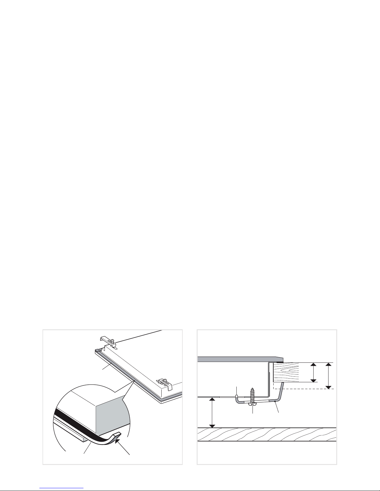
This cooktop can be built into a working surface 30 to 40 mm thick and 600 mm deep.
In order to install the ceramic hob into the kitchen xture, a hole with the dimensions shown
in gure 1 has to be made, keeping in consideration the following:
■The cooktop shall not be installed directly above a dishwasher, fridge, freezer, washing
machine or clothes dryer, as the humidity may damage the cooktop electronics.
■If the cooktop is installed above an oven, the oven shall be provided with cooling fan.
The two appliances should be connected to the electrical supply with independent
connections.
■IMPORTANT WARNING! This cooktop requires adequate supply of fresh, cool
air to fully function. The base of the cooktop must have direct unrestricted
ventilation to the room where the cooktop is installed. Follow the requirements
of gure 3 or 4.
■There must be a distance of at least 650 mm between the hob and any wall cupboard
or extractor hood positioned immediately above (see g. 2).
■We would point out that the adhesive which bonds the plastic laminate to the
furniture must withstand temperatures not less than 150° C to avoid delamination.
■The walls of the units must be capable of resisting temperatures of 75 °C above
room temperature.
■Do not seal the cooktop into the benchtop with silicone or glue; this makes
future servicing difcult. Delonghi will not cover the costs of removing the
cooktop, or of damage caused by this removal.
■The walls surrounding the cooktop must be made of heat-resistant material.
■Do not install the appliance near inammable materials (eg. curtains).
WARNING
When correctly installed, your product meets all safety requirements laid down for
this type of product category. However special care should be taken around the
underneath of the appliance as this area is not designed or intended to be touched
and may contain sharp or rough edges, that may cause injury.

7
490 50 (1)
270
290
510
A
A68 mm
from the top of
countertop to
bottom of cooktop
(1) at least 50 mm between the
back side of the cut-out and
the back of the countertop.
min 5 mm
min 30 mm
min 25 mm
min 5 mm
min 30 mm
min 25 mm
Minimum clearances and
ventilation requirements
(oven installed below)
Minimum clearances and
ventilation requirements
(cupboard or drawer space below)
Oven with
cooling fan
Figure 3 Figure 4
Figure 2
500 mm
650 mm
450 mm
60 mm minimum between the side
of the cut-out and the side wall
Figure 1

8
FASTENING THE COOKTOP
Each cooktop is provided with an installation kit including brackets and screws for fastening
the cooktop to benches from 30 to 40 mm thick.
The kit includes four “F” brackets and four self-threading screws “S” (g. 6).
■ Cut the unit according to the dimensions in g. 1.
■Turn the hob upside down and rest the glass side on a soft surface.
■Spread the seal “G” around the edge of the hob (g. 5).
■Fasten the brackets “F” to the appropriate socket holes, without tightening the screws
“S” for the moment. Make sure that the tabs are mounted correctly, as shown. Rotate
the tabs so that the cooktop can be put into the cutout.
■Put the cooktop into the cutout and position it correctly.
■Put the brackets “F” into place; tooth “A” of the brackets should go into the hole (g. 6).
■Tighten screws “S” until the cooktop is completely secured to the bench.
■ Using a sharp cutter or trimmer knife, trim the excess sealing material around the edge
of the cooktop. Take care not to damage the workbench.
3 cm
min
A
3 cm
4 cm
F
S
Adhesive side
G
G
Figure 5 Figure 6
25 mm

9
ELECTRICAL REQUIREMENTS
■The appliance must be connected to the mains checking that the voltage corresponds
to the value given in the rating plate and that the electrical cable sections can withstand
the load specied on the plate.
■A suitable isolating switch providing full disconnection from the mains power supply
shall be incorporated in the permanent wiring, mounted and positioned to comply with
the local wiring rules and regulations. The isolating switch must be of an approved
type and provide a 3 mm air gap contact separation in all poles (or in all active [phase]
conductors if the local wiring rules allow for this variation of the requirements).
■The isolating switch shall be easily accessible to the customer with the cooktop installed.
■The power supply cable must not touch the hot parts and must be positioned so that it
does not exceed 75°C above ambient.
■To connect the appliance to the mains electricity supply, do not use adapters, reducers
or branching devices as they can cause overheating and burning.
N.B. The connection of the appliance to earth is mandatory.
If the installation requires alterations to the domestic electrical system call a qualied
electrician. He should also check that the domestic electrical system is suitable for the
power drawn by the appliance.
Replacing the power cord (not supplied with the appliance) must be done by a
qualied electrician in accordance with the instructions supplied by the manufacturer
and in compliance with established electrical regulations.
CONNECTION OF THE POWER SUPPLY CABLE
Important! This cooktop must be connected to the electricity supply only by an
authorised person.
To connect the feeder cable to the hob it is necessary to carry out the following operations:
■Turn the cooktop over and unhook the terminal board cover by inserting a screwdriver
into the two hooks “A” (g. 7).
■Open the cable gland by unscrewing screw “F” (g. 8), unscrew the terminal screws.
■The supply cable, of suitable type and section, is connected to the terminal board
following the diagram in g. 9.
VOLTAGE AND POWER CONSUMPTION
220-240 V 50/60 Hz 3700 W 16.08 A

10
Figure 7 Figure 8
A
F
220-240 V
E
N
L
E E arth
N Neutral
L Live
FEEDER CABLE SECTION
This hob must be connected to electrical supply using V105 insulated cable.
220-240 V ac 3 x 2,5 mm2(*)
(*) Connection with wall box connection
If the supply cord (not supplied with the appliance) is damaged, it must be replaced
by the manufacturer or its service agent or a similarly qualied person in order to
avoid a hazard.
Figure 9

11
MS
UI
LB
ID200
ID160
TB
ELECTRIC DIAGRAMS
ELECTRIC DIAGRAM KEY
ID160 Induction zone, Ø 160 mm
ID200 Induction zone, Ø 200 mm
UI User interface
LB Lin-Bus
MS Main supply (L, N)
TB Terminal block
Figure 10

12
USE AND CARE
FEATURES AND TECHNICAL DATA
Figure 11
1. Induction cooking zone Ø 160 mm Normal Power: 1200 W
Booster Power: 1400 W
2. Induction cooking zone Ø 200 mm Normal Power: 2300 W
Booster Power: 3000 W
3. Touch controls
Note: The Nominal and Booster Power may change depending on the size and material of
the pan set on the cooking zone.
2
3
1

13
2 31
5
8
4
7
6
TOUCH CONTROLS
1. ON/OFF key
2. Rear cooking zone display
3. Front cooking zone display
4. Front cooking zone selector key
5. Rear cooking zone selector key
6. Automatic cooking (timer) display
7. Increasing key (power or timer)
8. Decreasing key (power or timer)
Notes:
■Each selection (by touching one of the keys) is indicated by an acoustic signal (beep).
■ The touch control area is switched off automatically (and a warning beep sounds):
– if one or more keys are touched for more than 10 seconds;
Attention: Detach the appliance from the mains if the ceramic glass is cracked and
contact the After-Sales Service. Metallic objects such as knives, forks, spoons and
lids should not be placed on the hob surface since they can get hot.
Figure 12

14
HOW TO USE THE COOKING HOB
= Cooking zone Off (not activated)
= Cooking zone On (activated but not operating).
If all the zones are in zero setting, the touch control system switches off
automatically (touch controls Off) after about 10 seconds.
÷ = Power levels
= “Booster” function
= Remaining heat indicator
= Pan detection indicator
= Child Lock safety
Note: Each lit gure (excluding the “Automatic cooking timer” display) refers to the relevant
cooking zone.
The ceramic hob is tted with induction cooking zones.
These zones, shown by painted disks on the ceramic
surface, are controlled by a touch control system.
In the front central area of the hob, the displays of the
touch control system
indicate:
INDUCTION COOKING SYSTEM
When your induction hob is switched On and a cooking zone has been selected, the
electronic circuits produce induced currents that instantaneously heat the bottom of the
pan which then transfers this heat to the food. Cooking takes place with hardly any energy
loss between the induction hob and the food.
Your induction hob operates only if a correct pan with the right features is placed on a
cooking zone. Please refer to COOKWARE FOR INDUCTION COOKING.
If the pan detection symbol appears on the display, your pan is not suitable and your
induction hob will not operate. After 10 minutes without detecting any pan, the cooking
zone switches Off automatically.
Figure 13

15
REMAINING HEAT INDICATORS
When the temperature of a cooking zone is still hot, the relevant remaining heat
indicator lights up on the display to alert you of the hot surface.
Avoid touching the hob surface over the cooking area. Please pay special attention to
children.
When the is lit on the display, it is still possible to start cooking again; just operate the
cooking zone as indicated in the chapter
POWER IGNITION AND ADJUSTMENT OF A
COOKING ZONE
.
COOKWARE FOR INDUCTION COOKING
The induction cooking system OPERATES ONLY if using correct cookware suitable for
induction cooking.
The bottom of the pan has to be ferromagnetic to generate the electromagnetic eld
necessary for the heating process (meaning a magnet has to stick to the bottom of the
pan).
Pans made from the following materials are not suitable:
■glass, wood, porcelain, ceramic, stoneware;
■pure stainless steel, aluminium or copper without magnetic bottom.
To check if a pan is suitable or not:
■ test the bottom of the pan with a magnet: if the magnet sticks, the pan is suitable.
■if a magnet is not available pour a small amount of water inside the pan and place the
pan on a cooking zone. Switch on the cooking zone: if the symbol (pan detection)
appears on the cooking zone display (instead of the power level), the pan is not
suitable.
Important note: the cooking zones will not operate if the pan diameter is too small (
pan detection symbol will appear on the cooking zone display). To correctly use the cooking
zones follow the indications given in the following table.
Induction cooking zone Minimum pan diameter recommended
(referred to the bottom of the pan)
Cooking zone Ø 160 mm 110 mm
Cooking zone Ø 200 mm 145 mm
Pay attention: The pan shall always be centred over the middle of the cooking zone. It
is possible to use oversized pans but the bottom of the pan cannot touch other cooking
zones.
Always use pans with thick, completely at bottom.
Do not use pans with concave or convex bottom; these could cause overheating of the
cooking zone.
Note: Some types of pans could cause noise when used on an induction cooking zone.
The noise does not mean any failure on the appliance and does not inuence the cooking
operation.

16
HOW TO SWITCH ON/OFF THE COOKTOP
Switching ON
Touch the key until the touch control
system is lit (g. 14). The displays of the
cooking zones read “ 0”.
Notes:
■If the safety Child Lock protection
is active, the cooktop can be used
only after having deactivated this
protection (see chapter CHILD LOCK
SAFETY).
■ Auto switch-Off: If a cooking zone is
not turned On within 15 seconds, the
cooktop will automatically switch off.
Switching OFF
The cooktop may be switched Off at any time by pressing the key .
If any cooking zones are turned On, they will be turned Off.
POWER IGNITION AND
ADJUSTMENT OF A COOKING
ZONE
To turn On a cooking zone the cooktop
must be switched On (see section “HOW
TO SWITCH ON/OFF THE COOKTOP”).
■Select a cooking zone by touching
the relevant key of the cooking zone
to be used (g. 15).
■Press the key and keep it
pressed until the desired power level,
ranging between 1and 9is set. As
an alternative, press the key . The
choice starts from level (maximum
level) down to (minimum level).
■To reset the power level press the
key and keep it pressed until
power level zero (0) .
■The cooking zone display shows the
selected level.
■ The power level can be modied at
any time.
Figure 14
Figure 15
Figure 16

17
BOOSTER FUNCTION
This function allows the cooking zone to operate at the “Booster” maximum power (above
the nominal power) for maximum 5 minutes; it could be used, for example, to rapidly heat
up large amount of water.
– The “Booster” function is always limited to a maximum of 5 minutes.
To activate the “Booster” function:
■Set the power level “ 9” on the selected cooking zone, then just touch the key until
the relevant display shows “ P ” (g. 17).
■ At the end of the “Booster” program (5 minutes) the cooking zone is automatically set
to the power level “ 9”.
■ Note: if a cooking zone is still hot, it is not possible to use the “Booster” function
and “ P” will ash if you try to activate. The cooking zone is automatically set to the
maximum power level (“ 9”).
To deactivate the “Booster” function:
■Set a different power level on the selected cooking zone.
or
■Switch Off the cooktop.
IMPORTANT NOTES:
■The “Booster” function is not suitable for use with non water based cooking.
■Do not use this function for heating oil (e.g. deep fat frying).
Figure 17

18
OPERATION TIME LIMIT OF
THE COOKING ZONES
Each cooking zone is automatically
switched Off after a maximum preset
time if no operation is performed.
The maximum preset time limit
depends on the set power level, as
illustrated in this schedule.
Each operation on the cooking hob by
using the touch controls will reset the
maximum operation time at its initial
value.
POWER LEVEL OF
COOKING ZONES
OPERATION
TIME LIMIT
480 minutes
360 minutes
300 minutes
300 minutes
240 minutes
90 minutes
90 minutes
90 minutes
90 minutes
5 minutes

19
EXAMPLES OF COOKING POWER SETTING
0Cooking zone not operating
1to 2Melting
Reheating
Sauces, butter, chocolate, gelatine
Dishes prepared beforehand
2to 3Simmering
Defrosting
Rice, pudding, sugar syrup
Dried vegetables, sh, frozen products
3to 4Steam Vegetables, sh, meat
4to 5Water Steamed potatoes, soups, pasta,
fresh vegetables
6to 7Medium cooking
Simmering
Meat, lever, eggs, sausages
Goulash, roulade, tripe
7to 8Cooking Potatoes, fritters, wafers
9Frying, roasting
Boiling water
Steaks, omelettes, fried dishes
Water
PRapidly heat up large amount of water
COOKING
ZONE
POWER
LEVEL
COOKING
ZONE
Ø 160 mm
(Watt power)
COOKING
ZONE
Ø 200 mm
(Watt power)
36 70
60 120
100 180
140 276
215 420
336 645
500 960
770 1470
1200 2300
1400 3000

20
PROGRAM FOR AUTOMATIC
SWITCHING OFF OF A COOKING
ZONE
This function permits to set a timer from “ 1”
to “ 99 ” minutes for automatic turning Off the
cooking zone/s.
With the cooktop switched On:
■Select the cooking zone and set the
desired power level.
■Within 8 seconds, touch the timer keys
and (the led indicating the
programmed zone starts blinking) and
set the timer:
By pressing the key the initial value
is “ 0 ” .
By pressing the key the initial value
is “ 30 ”.
■The time can be changed at any time
following the same procedure here
above indicated (selecting previously the
cooking zone).
■To program another cooking zone,
repeat as described above.
NOTE: The led indicating the cooking
zone closest to the end of the program, is
blinking. In the case of one programmed
zone only, the led is blinking.
Now the program for automatic switching Off
is complete.
At the end of the countdown the cooking
zone will switch Off automatically, an acoustic
signal (beep) will sound (for 2 minute only),
“ 00 ” will ash on the timer display and the
led next to the heater display will blink.
The program for automatic switch Off can be
cancelled at any time:
■by resetting the timer to “ 00 ”).
■by pressing the and keys at the
same time.
■ IMPORTANT: Remember to switch Off the
zone manually.
Figure 18
Figure 19
Figure 20
Figure 21
Table of contents
Other DeLonghi Cooktop manuals

DeLonghi
DeLonghi PVC 95 N Quick guide

DeLonghi
DeLonghi LGHW60 Quick guide

DeLonghi
DeLonghi DEGHSL60 Quick guide

DeLonghi
DeLonghi PVC 61 SK Quick guide

DeLonghi
DeLonghi DGHS70 Quick setup guide

DeLonghi
DeLonghi DEGH90STF Quick guide

DeLonghi
DeLonghi NSL 460 X Quick guide

DeLonghi
DeLonghi DEH60S User manual

DeLonghi
DeLonghi DEGCT424FSS User manual

DeLonghi
DeLonghi DEGH60STF Operating instructions