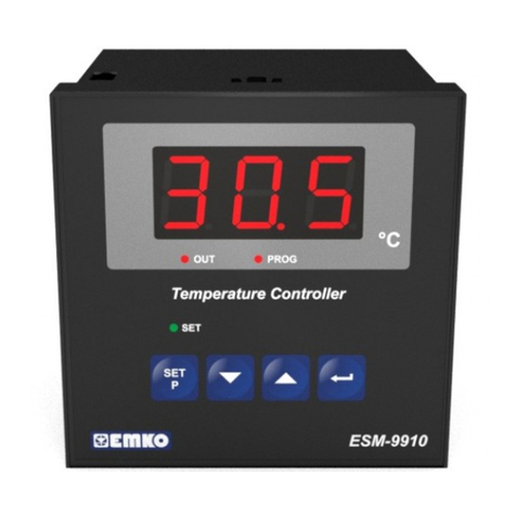
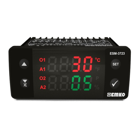
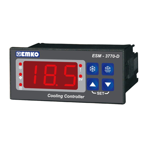
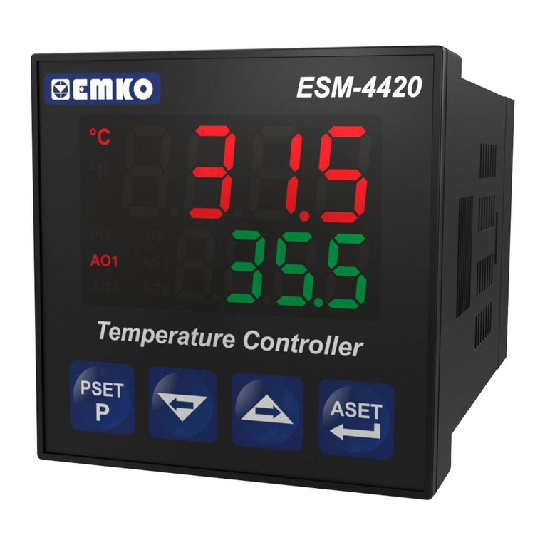
6. Changing and Saving Temperature Set Value
Main Operation Screen
When SET button pressed ‘’S’’ led will
be active and temperature set value will
be displayed.
SET Value Screen
Temperature set value can
be changed with increment
and decrement buttons.
When SET button pressed
temperature set value can be saved.
‘’S’’ will be inactive and goes back to
main operation screen.
Main Operation Screen
Temperature set value parameter (Default=30) MODBUS ADDRESS:40001
Temperature set value, can be programmed between minimum temperature set value and
maximum temperature set value .
4.2 Device Label and Connection Diagram
4. Electrical Wiring Diagram
4.1 Supply Voltage Input Connection of the Device
Note-1 :External fuse is recommended.
Make sure that the power supply voltage is the same
indicated on the instrument.
Switch on the power supply only after that all the electrical
connections have been completed.
Supply voltage range must be determined in order. While
installing the unit, supply voltage range must be controlled
and appropriate supply voltage must be applied to the unit.
c
There is no power supply switch on the device. So a power
supply switch must be added to the supply voltage input.
Power switch must be two poled for seperating phase and
neutral, On/Off condition of power supply switch is very
important in electrical connection.
External fuse that on Vpower supply inputs must be on
phase connection.
External fuse that on Zpower supply inputs must be on (+)
connection.
c
230VVCONNECTION DIAGRAM
5.Front Panel Definition and Accessing to the Menus
BUTTON DEFINITIONS
1. Increment Button :
** It is used to increase the value in the Set screen and Programming mode.
2. Decrement, Silencing Buzzer and Downloading to Prokey Button :
** It is used to decrease the value in the Set screen and Programming mode.
** It is used to silence the buzzer.
** If Prc =0, it is used to download from device to prokey.
3. Set Button :
** In the main operation screen; if this button pressed, set value will be displayed. Value can be
changed using increment and decrement buttons. When Set button pressed again, value is
saved and returns back to main operating screen.
** To access the programming screen; in the main operation screen, press this button for 5
seconds.
** It is used to saving value in the Set screen and programming screen.
4. Alarm Set Button :
** In the main operation screen; if this button is pressed, Alarm set value will be displayed. Value
can be changed using increment and decrement buttons. When Set button is pressed again,
value is saved and returns back to main operating screen.
LED DEFINITIONS
5. Cooling led :
** This led indicates that cooling control is selected and process output relay is active. If any of
compressor protection time active, this led blinks.
6.Heating led :
** This led indicates that heating control is selected and process output relay is active.
7.Alarm led :
** It is active in all alarm status.
8.Celcius led :
o
** Indicates that device is in C mode.
9.Fahrenheit led :
o
** Indicates that device is in F mode.
10.Alarm Set led :
** It is active when alarm statuses.
11.Set led :
** Indicates that device is in Set value changing mode.
12.Program led :
**Blinks in programming mode .
Cooling
Heating
Sensor Offset Parameter ( Default = 0 ) MODBUS ADDRESS:40007
from -20 to 20 °C for NTC(-50°C, 100°C) or PTC(-50°C, 150°C),
from -36 to 36 °F for NTC(-58°F, 212°F) or PTC(-58°F, 302°F),
from -10.0 to 10.0°C for NTC(-50.0°C,100.0°C) or PTC(-50.0°C,150.0°C),
from -18.0 to 18.0°F for NTC(-58.0°F,212.0°F) or PTC(-58.0°F,302.0°F),
Compressor Start Delay at Power On Parameter ( Default = 0)
MODBUS ADDRESS:40009
When power is first applied to the device, compressor is on when this time delay is expired.
It can be adjusted from 0 to 20 minutes.
Compressor Stop-Start Delay Parameter ( Default = 0) MODBUS ADRES:40010
When compressor is inactive, this time delay must be expired for activation of the
compressor. It can be adjusted from 0 to 20 minutes.
Compressor Start-Start Delay Parameter ( Default = 0) MODBUS ADRES:40011
This time delay must be expired between two activation of the compressor. It can be
adjusted from 0 to 20 minutes.
6.3 Modbus Adresses of Device Status Parameters (Read Input Register)
Operating Type Parameter ( Default = 0) MODBUS ADDRESS:40008
If parameter value is ‘0’ device skips to parameter
5 6 9 10
121187
1.Switch off the device.
2.Put in PROKEY then energize the device.
3.When the device is energized, the parameter values in PROKEY, start downloading to the device
automatically. At first, message is shown on the display, when loading has finished,
message is shown.
4.After 10 seconds device starts to operate with new parameter values.
5.Remove the PROKEY.
1-Before mounting the device in your panel,
make sure that the cut-out is of the right size.
2-Insert the device through the cut-out. If the
mounting clamps are on the unit, put out them
before inserting the unit to the panel.
3- Insert the mounting clamps to the fixing sockets
that located left and right sides of device and make
the unit completely immobile within the panel
3
1-Pull mounting clamps from left and right fixing
sockets.
2-Pull the unit through the front side of the panel
Before starting to remove the unit from
panel, power off the unit and the related
system.
c
2.3 Panel Mounting
2.4 Removing from the Panel
3. Using Prokey
DOWNLOADING FROM DEVICE TO PROKEY
1.The device is programmed by using the parameters.
2.Energize the device then put in PROKEY and press button. Message is shown on the
display. When the loading has finished, message is shown.
3.Press any button to turn back to main operation screen.
4.Remove the PROKEY.
DOWNLOADING FROM PROKEY TO DEVICE
NOTE: message is shown when an error occurs while programming. If you want to reload, put
in PROKEY and press button. If you want to quit, remove PROKEY and press button. The
device will turn back to main operation screen.
NOTE: message is shown when an error occurs while programming. If you want to reload,
switch off the device and put in PROKEY then energize the device. If you want to quit remove
PROKEY and press button. The device will turn back to main operation screen.
TO USE PROKEY, VALUE OF THE PrC PARAMETER MUST BE ‘0’.
IF PrC=1 AND BUTTON IS PRESSED MESSAGE WILL BE SHOWN. 10s. LATER
DEVICE TURNS BACK TO THE MAIN OPERATION SCREEN OR YOU CAN PRESS SET
BUTTON TO TURN BACK TO MAIN OPERATION SCREEN.
1
3
6.2 Programming Mode Parameter List
Hysteresis Parameter for Compressor Output ( Default = 1 )
MODBUS ADDRESS:40004
from 1 to 20°C for NTC (-50°C, 100°C) or PTC (-50°C, 150°C),
from 1 to 36°F for NTC (-58°F, 212°F) or PTC (-58°F, 302°F),
from 0.1 to 10.0°C for NTC(-50.0°C,100.0°C) or PTC (-50.0°C,150.0°C),
from 0.1 to 18.0°F for NTC (-58.0°F,212.0°F) or PTC (-58.0°F,302.0°F),
In ON/OFF control algorithm, temperature
value is tried to keep equal to set value by
opening or closing the last control element.
ON/OFF controlled system, temperature
value oscillates continuously. Temperature
value’s oscillation period or amplitude around
set value changes according to controlled
system. For reducing oscillation period of
temperature value, a threshold zone is formed
below or around set value and this zone is
named hysteresis.
ON
OFF
Temperature
Control
Output
Set
HSt
Time
HSt
Time
Minimum Temperature Set Value Parameter (Default = Minimum Value of Device
Scale ) MODBUS ADDRESS:40005
Temperature set value can not be lower than this value.
This parameter value can be adjusted from minimum value of device scale to maximum
temperature set value parameter
Maximum Temperature Set Value Parameter (Default = Maximum Value of Device
Scale )MODBUS ADDRESS:40006
Temperature set value can not be bigger than this value.
This parameter value can be adjusted from minimum temperature set value parameter
to maximum value of the device scale
Decimal Seperator Enabling Parameter ( Default = 0 ) MODBUS ADDRESS:40003
Disable.
Enable.
Temperature Unit Selection Parameter ( Default = 0 ) MODBUSADDRESS:40002
°C selected.
°F selected.
Sensor Defect Parameter ( Default = 0 ) MODBUS ADDRESS:40012
Compressor is active during this time period in case of probe defect (Default = 0)
MODBUS ADDRESS:40013
If probe defect parameter is 2, then this parameter is observed. It can be adjusted
from 0 to 99 minutes.
Compressor is OFF in case of sensor defect.
Compressor is ON in case of sensor defect.
Compressor operates periodically according to and Time periods in
case of sensor defect.
Compressor is inactive during this time period in case of probe defect
( Default = 0 )MODBUS ADDRESS:40014
If probe defect parameter is 2, then this parameter is observed. It can be adjusted
from 0 to 99 minutes.
Buzzer Function Selection Parameter ( Default = 0 ) MODBUS ADDRESS:40023
Buzzer is inactive.
Buzzer is active if an alarm occurs.
Buzzer is active during this time
When this parameter is 1, if decrement button is pressed, is observed. In this
condition buzzer is active till buzzer silence button is pressed.
( Default = ) MODBUS ADDRESS:40024
If buzzer function selection parameter value =0, this parameter can not be
observed. Buzzer stays active during this time. It can be adjusted from 1 to 99 minutes
Programming Section Accessing Password 27
.
( Default = 0 ) MODBUS ADDRESS:400
It is used for accessing to the programming section. It can be adjusted from 0 to 9999. If it is
selected 0, password will not be asked
PROKEY communication selected.
Communication Mode Selection Parameter 25( Default = 0 ) MODBUS ADDRESS:400
RS 485 communication selected.
Slave ID Parameter 26( Default = 1 ) MODBUS ADDRESS=400
Device communication address parameter (1 to 247).
Power Supply Connection
c
a
EXTERNAL
FUSE
(1A T)
Note-1
Supply
Switch
Supply Voltage
45
LN
2
Buzzer is active during sensor failures.
Buzzer is active during alarm or sensor failures.
6.1 Changing and Saving Alarm Set Value
230V ( %15) 50/60Hz ,
115V ( %15) 50/60Hz ,
Z
V±
V±
10...30 V -1.5 W
Must be determined in order.
, , , , and Parameters are observed if Operation type
is selected “Cooling”. If operation type is selected “Heating ” ,skip to the parameter.
i
Process and Alarm
Relay Outputs
Supply Voltage Input
Temperature Sensor
Input (NTC or PTC)
230V ( %15) 50/60Hz
115V ( %15) 50/60Hz
Z
V±
V±
10...30 V
Must be determined in order.
ü
OF
OCP
S
58
11
12
1
23
9
A
6
7 10
A
S
4
OF
OCP
S
ü
S
A
OF
OCP
S
ü
ü
S
A
OF
OCP
S
ü
S
A
OF
OCP
S
ü
S
A
21 4 5 6 7
P/N : ESM-3712-HCN
L
N
aa
3
Alarm Type Selection Parameter ( Default = 2 )MODBUS ADRESS:40015
Sensor Break Alarm
Process High Alarm
Process Low Alarm
Deviation High Alarm
Deviation Low Alarm
Deviation Band Alarm
Deviation Range Alarm
Alarm Set Value Low Limit Parameter ( Default = Minimum Value of Device Scale)
MODBUS ADDRESS:40016
Alarm set value can not be lower than this value.This parameter value can be adjusted
from minimum process set value parameter to alarm set value high limit parameter
value.
Alarm Set Value High Limit Parameter ( Default = Maximum Value of Device Scale)
MODBUS ADDRESS:40017
Alarm set value can not be greather than this value.This parameter value can be
adjusted from alarm set value low limit parameter value to maximum process set value
parameter.
Alarm On Delay Time Parameter( Default = 0 ) MODBUS ADDRESS:40018
It can be adjusted from 0 to 99 minutes.
Alarm Off Delay Time Parameter( Default = 0 ) MODBUS ADDRESS:40019
It can be adjusted from 0 to 99 minutes.When this parameter is 99, if increment button is
pressed, is observed and alarm latching output is selected. To make the alarm latching
output passive,decrement button must be pressed in main operation screen.
Alarm Delay Parameter After Power On
This parameter defines the delay for the alarm is being active after power on.It can be
adjusted from 0 to 99 minutes.
( Default = 0 )MODBUS ADDRESS:40020
Alarm Set Value Parameter ( Default = 20 )MODBUS ADDRESS:40021
Alarm output is controlled according to this value.For alarm type selection paramater
=1 or 2,this parameter value is can be adjusted from alarm set value low limit
parameter to alarm set value high limit parameter,for alarm type selection parameter
=3,4,5 or 6 this parameter value is can be adjusted from 0 to alarm set value high limit
parameter.
Alarm Hysteresis Parameter
Alarm hysteresis value.
( Default = 0 )MODBUS ADDRESS:40022
This parameter is can be adjusted 0 to %50 of the device scale.
MODBUS ADRES:30001 Temperature Value
o
MODBUS ADRES:30002 Led Status : 0.bit C Led,6.bit Compressor Led,
7.bit Alarm Led, 13.bit Program Led,
14.bit Set Led
MODBUS ADRES:30003 Device Status : 0.bit Alarm Status
2.bit Buzzer Status
3.bit Sensor Break Status
MODBUS ADRES:30004 Output Status 0.Bit Compressor Output,1.bit Alarm Output
MODBUS ADRES:30005 Device Type and Device Version
A
6.4 Operation Graphics of Alarm Output and Alarm Types
Power
Time
Alarm
Status
Alarm
Output
Active
Led
°C
Time
Time
Time
Alarm
Output
Power
Time
Alarm
Status
Alarm
Output
Active
Led
°C
Time
Time
Time
Alarm
Output
=
( Alarm Latching Output is Selected )
Decrement
Button must
be pressed
to make alarm
output is
passive.
6.4 Operation Graphics of Alarm Output and Alarm Types
ON
OFF
Alarm
Output
Process Value
Process Low Alarm
ON
OFF
Alarm
Output
Process Value
Deviation High Alarm
Deviation Low Alarm
ON
OFF
Alarm
Output
Process Value
( + )
ON
OFF
Alarm
Output
Process Value
( - )
Deviation Band Alarm
ON
OFF
Alarm
Output
Process Value
( - )
( + )
= Process Set Value
i= Alarm Set Value
Deviation Range Alarm
ON
OFF
Alarm
Output
Process Value
( - ) ( + )
Process High Alarm
Main Operation Screen
When ALARM SET button pressed ‘’A’’
led will be active and temperature set
value will be displayed.
ALARM SET Screen
Alarm set value can be
changed with increment and
decrement buttons.
OF
OCP
S
OF
OCP
S
ü
S
A
ü
S
A
AA
Main Operation Screen
OF
OCP
S
ü
S
A
A
ALARM SET Screen
When SET button pressed
Alarm set value can be
saved.
OF
OCP
S
ü
S
A
A
Alarm set Value saved,
’A’ will be inactive and goes back to
main operation screen.
ü
S
A
If no operation is performed in Alarm set value changing mode and process set value changing
mode for 20 seconds, device turns to main operation screen automatically.
i
1
2
PROKEY
RS-485
or
67
a
16(8)A
@250V 1HPV
LN
245
1
PTC
L
N
16A T Sigorta
NO
C
3
NO
COMP. ALARM
5A@250VV
230 VV± 15%
50/60Hz - 1.5VA
+-
230 VV± 15%
50/60Hz - 1.5VA
P/N : ESM-3712-HCN - 5.12.0.1/01.00/2.1.0.0
LINE
PROKEY
RS-485
or
C NO
COMP.
1 2 3 4 5 67
ALARM
NO
16(8)A @
250V 1HPV5A@250VV
LOAD
PTC
INPUT SCALE
(-50 ,150 ;°C °C °F °F-58 ,302 )
