Yamaha 40XMH User manual

MODEL BC FOR 40 HP YAMAHA SERIES
ASSEMBLY INSTRUCTIONS
YAMAHA MODEL 40XMH, 2 CYLINDER, 2 STROKE, 42.9 CU. IN.
1
1. Place the engine on the transom of your boat in the normal fashion. Disconnect the shift rod coupling. Remove
the 5 bolts holding the gearbox to the exhaust housing and remove the gearbox assembly.
2. Remove the water pump assembly from the propeller drive, including the lower stainless steel plate and the
dowel pins.
3. Install the jet driveshaft assembly into the spiral pump housing locking it in place with the four ¼-20 x ¾ bolts
and lockwashers. Use grease on the threads. Tighten to 8 ft-lbs.
4. Insert the clear plastic ½ long x 3/8 dia. Sleeve in the 3/8 hole in the main housing, just ahead of the cooling
water pump.
Install the water pump assembly on top of the stainless steel plate, using 4—M8 x 30MM bolts and the special
steel washers under the bolt heads. Be sure also, to install the water pump impeller drive key and dowel pins.
Grease the threads. Before tightening the bolts, press the 2 ¾ long x ½ dia. Plastic shift rod guide into the clear
plastic sleeve, through the stainless steel plate, until it bottoms. Tighten the bolts.
Remove the nut and hex coupling from the gearbox and motor mid section shift rods. Thread the nut and
coupling all the way onto the shift rod guide #1911, and tighten the nut against the coupling. Thread the
coupling onto the motor shift rod and tighten it against the shift rod.
5. Remove the plastic water tube guide and rubber sleeve from the outlet of the cooling pump. Install the 5/8 dia.
X 3/8 long plastic spacer in the outlet, followed by the rubber sleeve and the brass water tube extension. If
there is a burr on the end of the motor cooling tube, file it smooth so the “O” ring inside the water tube
extension will slide on.
6. The large ¾” adapter plate is attached to the exhaust housing to hold the jet drive. Two 6 x 16mMM dowels
locate the plate, four M10 x 35MM bolts with lockwashers and one M8 x 30 MM bolt with lock washer secure
it. Grease the bolt threads.
7. Next, attach the jet drive to the motor. Use two 5/16-18 x 2-1/2 bolts (front), tow 5/16-18 xxx 2-3/4 bolts (rear)
from below with lockwashers, one 3/8-16 x 1-1/2 bolt and lockwasher, above rear, inside the motor mid-section
and two 3/16 x ½ dowel pins.
Grease the bolt threads, driveshaft spline generously, and rubber water tube pilot and guide the jet into place.
Tighten the 5 bolts.
8. Next, install the impeller. Grease the shaft threads, key and impeller bore. Place the plastic sleeve inside the
impeller, hold the key in the nose of the impeller with your forefinger and slide onto the driveshaft. Install the
eight shim washers and nut retainer on the shaft, up against the impeller, and bring he nut up snug by hand.
Place the water intake in position and secure with 2 bolts. Observe the clearance between the impeller blade
edge and the intake liner. Then remove the intake.
When, after use in sand and gravel, the blade clearance becomes more than about 1/32 inch between the
impeller edge and the water intake liner, one or more of the stainless shim washers can be transferred from the
bottom stack to the top of the impeller, which moves the impeller down into the tapered casing to reduce the
clearance.
Shims should not be used above the impeller on new installations, where no wear has occurred, unless the blade
clearance exceeds 1/32 inch. Insufficient blade clearance will do more harm than good from any performance
gains it might provide.

MODEL BC FOR 40 HP YAMAHA SERIES
ASSEMBLY INSTRUCTIONS
YAMAHA MODEL 40XMH, 2 CYLINDER, 2 STROKE, 42.9 CU. IN.
2
When the impeller clearance is satisfactory, bump the nut up snug with a wrench. If the ears of the retainer do
not line up with the flats on the nut, spin the nut off, turn the retainer over and tighten the nut again. In one of
these two positions you will have alignment and can fold the ears up against the nut to retain it. The flat in the
retainer is angled to the ears to allow this.
9. Place the intake casing in position with the lower end at the rear and tighten the six ¼-20 fiber lock nuts. No
lockwashers are used. Grease the threads.
10. If your jet drive was ordered for use with a steering tiller handle, see attached page 4, “Shift Cable and Handle
Assembly Instructions attached, #1914
11. If your motor uses remote controls, attach the shift cable and cable anchor bracket to the jet drive. Slide the
bracket all the way forward and lock the bolts. With the shift handle in forward and the reverse gate in forward,
and with the cam roller at the end of the slot, adjust the cable and/or cable anchor position to this condition.
Shift to reverse and back to forward. The roller should be at the end of the cam slot such that the gate cannot be
forcibly rotated toward reverse. Pull on the gate by hand to verify this. If this forward lock condition is no met,
readjust the cable positions.
12. When converting to jet drive, your motor will have to be raised to height shown in diagram on page 3, using a
straight edge under the boat. Test run the boat and then raise or lower the motor 5/16 inch at a time to obtain the
best results. If you raise it too much it will suck air and cavitate, either on start up or when banking on turns.
When cavitating, the motor overspeeds in spurts and shakes considerably in the motor mount. This is not a
normal condition and should be avoided by proper adjustment of motor height on each individual boat. If you
lower it too much you will have excessive drag, therefore mount the motor as high as possible without allowing
cavitation.
The motor has four sets of upper mounting holes. You will use one set to begin with. Mark pencil lines on the
boat transom through the other sets. Then if you wish to go up or down 5/16 inch, you can drill one alternate
set of holes 5/16 inch up or down from the pencil marks. By alternating between these two sets of transom
holes and the four sets of motor holes, the motor can be moved in 5/16 inch increments over almost one inch.
The transom height should be about 21 inches measured vertically from the boat bottom for short shaft motors
and 26 inches for long shaft.
CAUTION
When starting the engine for the first time, watch to see that cooling water comes out of the small hole at the
rear side of engine just below the powerhead. This is to check your assembly of the cooling water pump and its
connections.

MODEL BC FOR 40 HP YAMAHA SERIES
ASSEMBLY INSTRUCTIONS
YAMAHA MODEL 40XMH, 2 CYLINDER, 2 STROKE, 42.9 CU. IN.
3
SETTING MOTOR HEIGHT
CAUTION
When starting the engine for the first time, watch to see that the cooling water comes out of the small hole
at the rear side of the engine just below the power head. This is to check your assembly of the cooling
water pump and its connections.
MAINTENANCE AND LUBRICATION
See last page
STRAIGHT
EDGE

TILLER SHIFT CABLE ASSY
YAMAHA MODEL BC 40 HP
1914
4
1. Cut out the paper template for the shift handle and attach it to the shift handle with masking tape. Drill
through using a ¼ inch drill. After drilling through the first side, align the drill carefully to come out
square and centered on the second side.
2. Install the four inch bolt with washer through the handle followed by the black handle #1906, washer
and nut. Tighten the nut.
3. Clamp the cable anchor on the engine pan up against the rim. Center it with the raised rib inside the
pan so that the mounting bolts will straddle the rib. Drill through the pan using a ¼ inch drill. Install
two ¼-20 x 5/8 hex head bolts and fiber lock nuts.
4. Attach the shift cable to the bracket with the shim between the cable and bracket, using two 10-24 x
5/8 screws and lock nuts.
5. Thread the rod end on the cable, threaded on about 3/8 inch. Slide the rod end on the shift handle bolt
and install the outer lock nut, flush with the end of the bolt. Be sure this leaves about 1/16 inch slide
play for the rod end between the nuts.
6. Direct the other end of the cable through the gap between the motor mount and motor mid section to the
starboard side. Attach the cable anchor bracket to the jet drive, centered over the slots. Attach the
cable to the anchor bracket and the reverse gate cam rod end.
7. The cable anchor brackets have the lower holes slotted so that the cable can be lined up for free cable
travel. Make this adjustment at both ends of the cable and tighten the screws.
8. Place the shift handle in forward, solidly in the detent. The reverse gate cam roller must be at the end
of the slot in the cam. If these conditions are not met, slide the cable anchor bracket on the jet drive
and/or adjust the threaded rod end on the cable.
9. Shift to reverse and back to forward. Do not be concerned if the gate does not reach reverse. There is
clearance at this position and water pressure will close the gate.
10. In forward, with the roller at the end of the cam slot, the gate cannot be forcibly rotated toward reverse.
Pull on the gate by hand to verify this.
11. Lock the nuts on the cable against the rod ends to complete the adjustment.
CAUTION! YOU MUST RETURN THE THROTTLE TO IDLE BEFORE SHIFTING.

MAINTENANCE AND LUBRICATION
OUTBOARD JET DRIVE
3
BEARING LUBRICATION
A grease gun and tube of grease is supplied with your jet drive. We recommend greasing
the bearing every 10 hours. Make greasing a part of your cleanup after the days use.
Pump in just enough grease to fill the lube hose. Then reconnect the lube hose coupling to
the zerk grease fitting.
Every 30-40 hours, pump in extra grease so as to purge any moisture. The texture of the
grease coming out gives an indication of conditions inside the bearing housing. A gradual
increase in moisture content indicates seal wear. If the grease begins to turn dark, dirty
gray, the bearing and seals should be inspected and replaced if necessary. Some
discoloration of the grease is normal during the break in period on new sets of seals.
We have selected a water resistant grease of the proper consistency for this application. If
you use a substitute grease, be sure it is water resistant and of the same consistency.
IMPELLER
Your jet drive is equipped with a key to protect the unit in the event of a rock jam. This can be
reached by removing the water intake, and then the driveshaft nut, similar to a propeller drive.
After replacing the key, pull the shaft nut up tight to remove any play between the impeller and
shaft. Note the position of the impeller shim washers, and replace them in the same order.
REVERSE GATE MECHANISM
Occasionally check adjustment of the gate shifting linkage. In “forward” the gate should be
firmly locked in position. Pull on the gate by hand to verify this. This will prevent wave action
from accidentally shifting the gate into reverse as the boat is violently maneuvered
GENERAL
Check all mounting bolts, intake screws, linkage connections, etc., occasionally to be sure they
are tight.
SALT WATER USE
Aluminum and stainless steel have been used in the construction of your jet drive. These
materials have either been treated or are inherently resistant to corrosion. It is recommended,
however, that when not in use the motor be tipped up so that the jet unit is out of the water.
When used in salt water more than in fresh water, remove mounting hardware, grease, and
reassemble once a year. Failure to do this may result in hardware that is difficult if not
impossible to remove at a later date.
GUARANTEE
Due to inflexible government regulation, we do not have a written warranty. We have, however,
a good reputation for fairness with our customers which we intend to maintain. If you think you
have a warranty situation, regarding material, workmanship, call us before making repairs.
Specialty Manufacturing Company
Outboard Jets
2035 Edison Avenue
San Leandro, CA 94577

SHIFT CABLE ASSEMBLY
YAMAHA MODEL BC
TILLER STEERING
1914
REF QTY PART DESCRIPTION
NO.
1 1 547 CABLE 4 FT MOR 33C SUPREME
2 1 543 CLAMP CHRYS 154317
3 1 542 SHIM MORSE A035777
4 2 561 FIL HD SLOTTED 10-24 X 5/8
5 2 619 NYLOC 10-24
6 1 553.2 BALL END 1/4X10-32 CABLE
7 1 1913 SHIFT HANDLE SHAFT ASSY BC
8 2 633 WASHER 1/4 X 1
9 1 1906 SHIFT HANDLE BC YAM
10 4 623 NYLOC 1/4-20
11 2 572 BOLT HEX HD 1/4-20 X 5/8
12 1 1905.1 CABLE ANCHOR BC FORMED

MODEL BC
ANODE KIT 1693

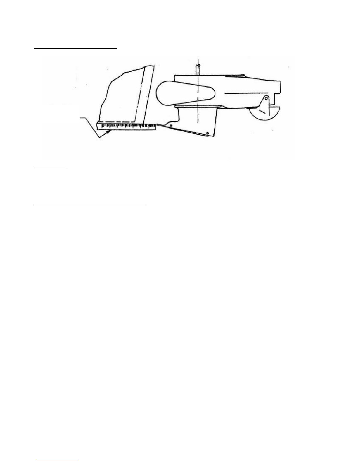
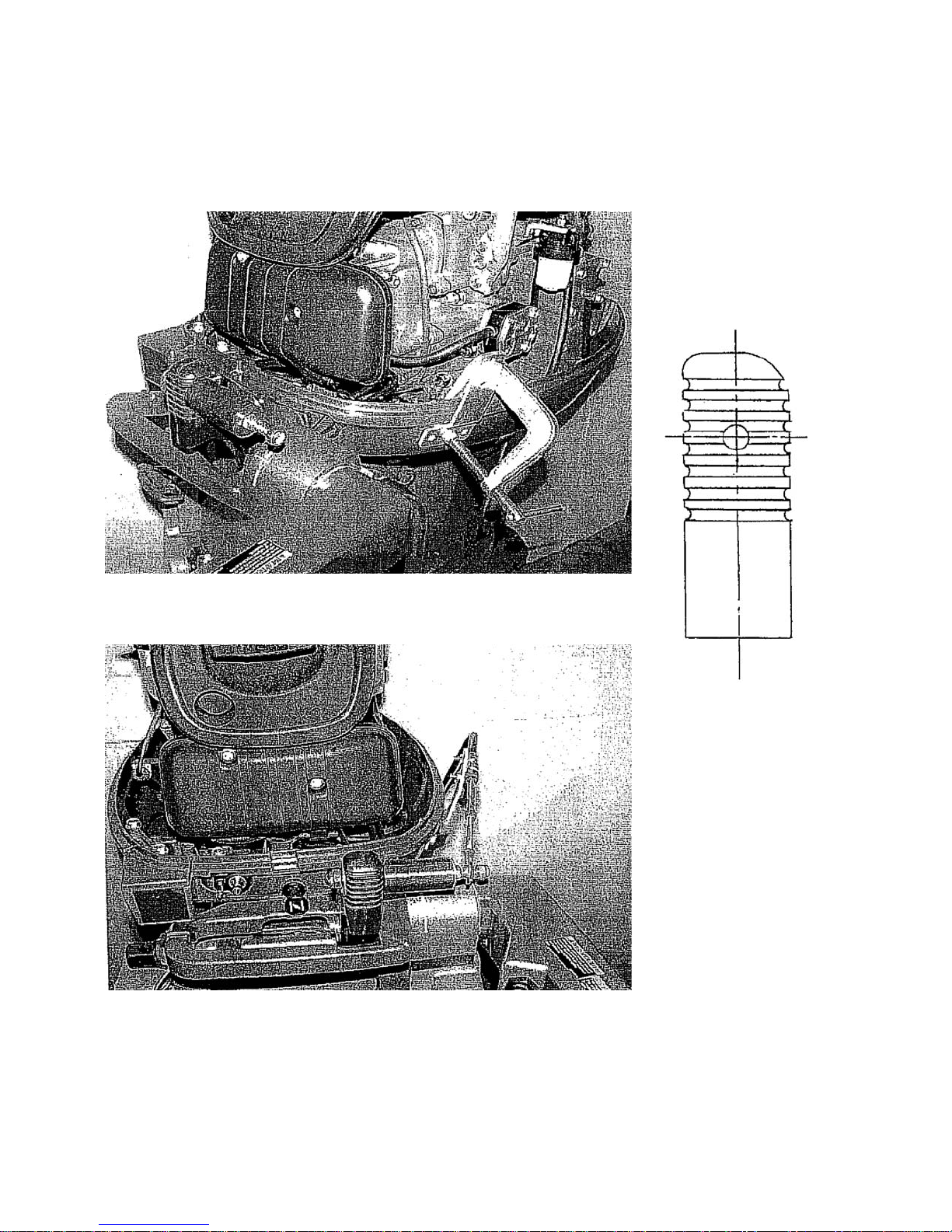
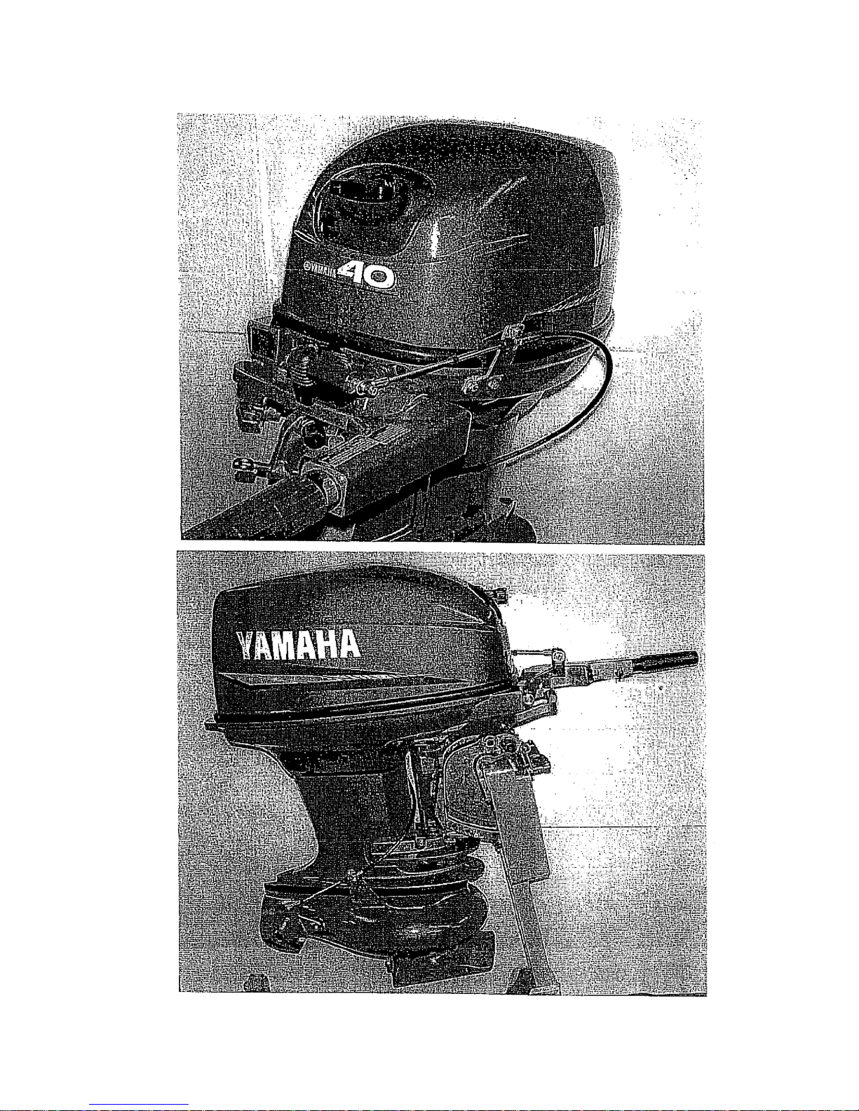
MODEL BC YAMAHA 40XMH 2 STROKE 2 CYL 40HP, 42.9 CU. IN.
REF QTY PART DESCRIPTION REF QTY PART DESCRIPTION
NO. NO.
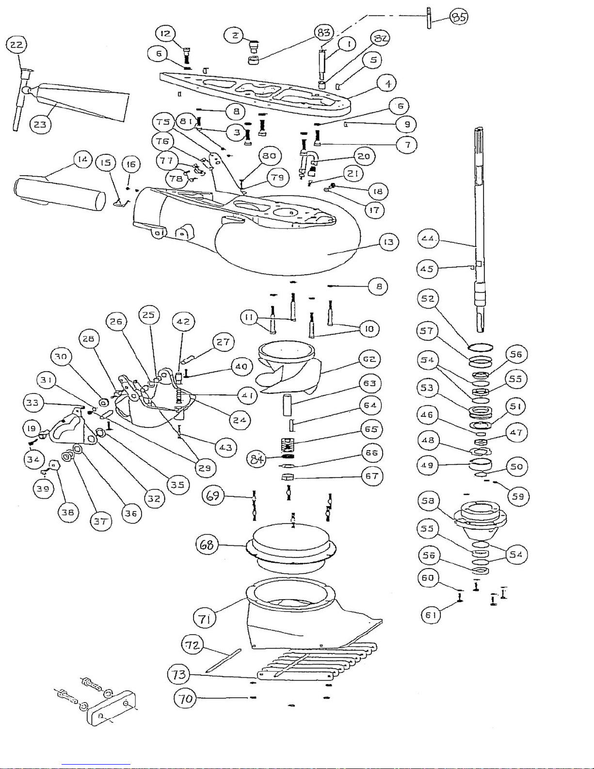
1 1 1910 SHIFT ROD TUBE BC 48 1 1536 THRUST WASHER
2 1 1377 WATER TUBE EXTENSION - AJ 49 1 504 BEARING 7205B-UA
3 1 591 BOLT HEX HD M8-1.25 X 30MM 50 1 511 TRUARC 5100-98
4 1 1366 ADAPTER PLATE AJ 51 1 1535 SPACER
5 2 616 DOWEL PIN 6 X 16 MM 52 1 512 TRUARC N5002-212ZD
6 5 636 WASHER SPRING LOCK M10 53 1 433 UPPER SEAL CARRIER W/ SEALS & O RINGS
7 4 592 BOLT HEX HD M10-1.25 X 35MM 54 4 517 SPIROLOX RR-150S
8 5 640 WASHER SPRING LOCK 5/16 55 2 506 SEAL INNER
9 2 631 DOWEL PIN 3/16 X 1/2 56 2 507 SEAL OUTER 6324-S
10 2 603 BOLT HEX HD 5/16-18 X 2 1/2 57 2 526 O RING 568-135 3/32X1 15/16X2 1/8
11 2 599 BOLT HEX HD 5/16-18 X 2 3/4 58 1 1932 BEARING CARRIER W/SEALS & O RINGS BC
12 1 607 BOLT HEX HD 3/8-16 X 1 1/2 59 3 521 O RING 568-011 1/16X5/16X7/16
1918 VOLUTE WITH GATE BC 60 4 638 WASHER SPRING LOCK 1/4
13 1 1917 VOLUTE WITH EXHAUST TUBE BC 61 4 573 BOLT HEX HD 1/4-20 X 3/4
14 1 80 EXHAUST TUBE ASSY MEDIUM 2 62 1 8.23 IMPELLER 6 1/8 W/36 SLEEVE
15 1 846 CLIP EXHAUST TUBE 1 62 1 1737 IMPELLER 6 1/8 W/36 SLEEVE, STAINLESS
16 2 621 NYLOC 10-32 63 1 36.1 SHAFT SLEEVE PLASTIC MEDIUM
17 1 1025 WASHER FIBER M8 64 1 1705 IMPELLER TEE KEY - 1/2 ROUND
18 1 1024 BOLT HEX HD M8-1.25 X 12 65 8 21 SHIM WASHER MEDIUM
19 1 553.2 BALL END 1/4X10-32 CABLE 66 1 805 NUTKEEPER MED/PKG 2 PER BAG
20 1 975 LUBE HOSE ASSY 67 1 22.1 SHAFT NUT 5/8-18 BRASS
21 1 539 ZIRC FITTING 1/4-28 1447 INTAKE ASSY 6 1/8 FLANGED W\ GRILL & LINER
22 1 550 GREASE GUN 68 1 1521 LINER 6 1/8 FLANGED
23 1 552 GREASE 10 OZ TUBE 630-AA 69 6 1300 STUD - INTAKE MEDIUM
24 1 1175 REVERSE GATE, MEDIUM 70 6 623 NYLOC 1/4-20
25 2 535 NYLINER 3/8 1D X 11/16 71 1 1326 INTAKE PAINTED ONLY MED FLANGED
26 1 1177 SPRING GATE PIVOT 3/8 72 2 14 GRILL ROD
27 2 822 PIN GATE PIVOT 3/8 MEDIUM 73 9 16 GRILL BAR MEDIUM
28 1 1043 SHAFT ROLLER 171 BRACKET ASSY MORSE W/CLAMP & HARDWARE
29 2 624 NYLOC 1/4-28 75 1 156 BRACKET CABLE SUPPORT
30 1 1042 ROLLER ASSY 76 1 542 SHIM MORSE A035777
31 1 635 1/4 WASHER AN960C416 77 1 543 CLAMP CHRYS 154317
32 1 1035 SHIFT CAM MEDIUM 78 2 561 FL HD SLOTTED 10-24 X 5/8
33 1 623 NYLOC 1/4-20 79 2 635 1/4 WASHER AN960C416
34 1 573 BOLT HEX HD 1/4-20 X 3/4 80 2 572 BOLT HEX HD 1/4-20 X 5/8
35 1 1037 BUSHING CAM 81 2 619 NYLOC 10-24
36 1 1038 WASHER CAM 82 1 1650 CUSHION-SHIFT ROD GUIDE
37 2 1039 SHIM-CAM 83 1 1912 SPACER-WATER TUBE
38 1 1036 CAM ECCENTRIC DRILLED 84 1 1718 TORSIONAL DAMPER 5/8
39 1 574.1 BOLT HEX HD 1/4-20 X 1 PATCH 85 1 1911 SHIFT ROD GUIDE
40 2 574 BOLT HEX HD 1/4-20 X 3/4 PATCH
41 1 1170 SPRING GATE BUMPER
42 1 1169 GATE BUMPER
43 1 559.2 FIL HD SLOTTED 10-32 X 1 1/4 PATCH
44 1 1908 SHAFT ONLY, BC, 14T 26 3/8 LG
1909 SHAFT ASSY COMPLETE, BC, 14T W/1275 KEY
45 1 1275 KEY, TEE WATER PUMP
46 1 41 SHAFT BEARING THRUST RING
47 1 477 COLLAR BACKFIT 7205
SIZE TORQUE
1/4-20 (M6) 8-9 FT-LBS
5/16-18 (M8) 12 FT-LBS
3/8-16 (M10) 22 FT-LBS
TILLER STEERING
SHIFT CABLE ASSY 1914
BEARING, SEAL, SNAP & “O” RING KIT 803.1

MODEL BC

MODEL BC
Table of contents
Other Yamaha Engine manuals

Yamaha
Yamaha T 135 SE User manual

Yamaha
Yamaha F15B User manual

Yamaha
Yamaha F25A User manual

Yamaha
Yamaha F60C User manual

Yamaha
Yamaha MZ175 User manual

Yamaha
Yamaha MZ250 User manual

Yamaha
Yamaha 396 Service manual

Yamaha
Yamaha F200 User manual

Yamaha
Yamaha YSE series User manual

Yamaha
Yamaha VF150 User manual