Delta OHM HD2016 User manual
Operating manual
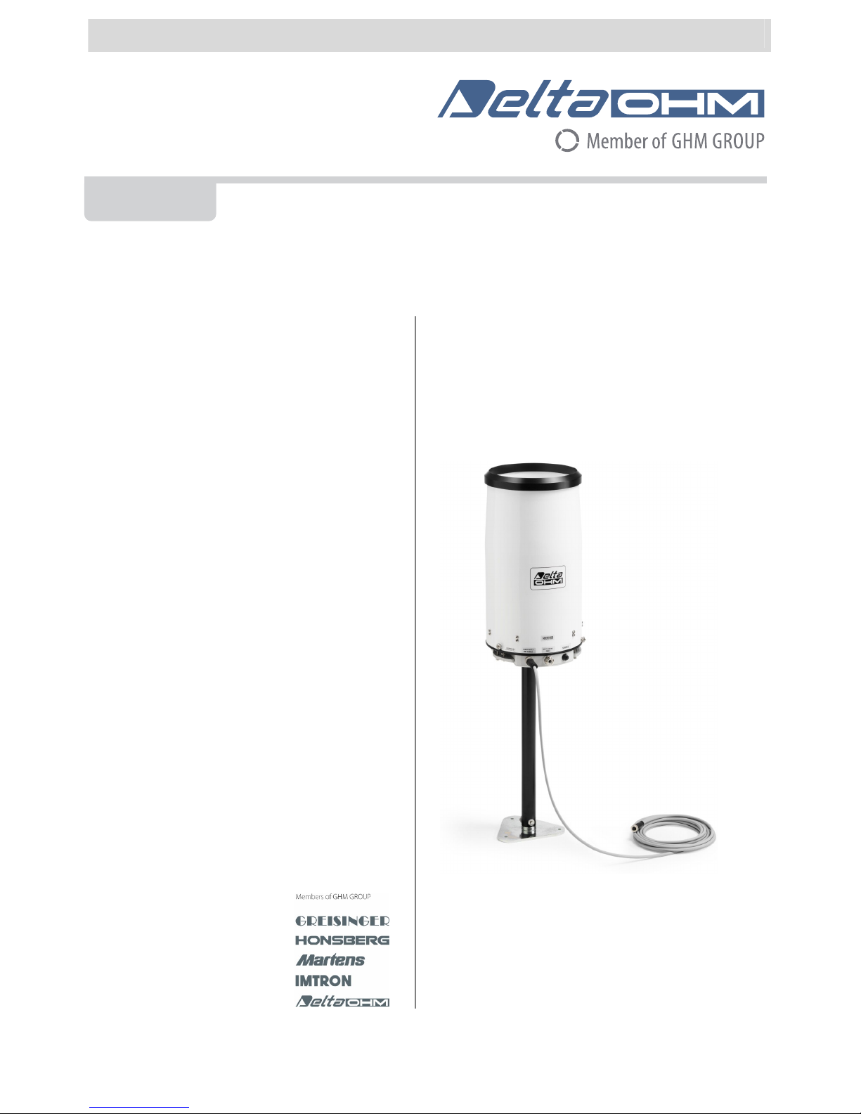
Weighing rain gauge
HD2016
www.deltaohm.com
Companies / Brands of
GHM
English
Keep for future reference.

HD2016 - 2 - V1.4
TABLE OF CONTENTS
1INTRODUCTION.................................................................................................... 3
2DESCRIPTION....................................................................................................... 4
3INSTALLATION ..................................................................................................... 6
3.1ELECTRICAL CONNECTIONS ..................................................................................... 6
3.2CHOOSING THE DIGITAL OUTPUT AND THE PROTOCOL....................................................... 7
3.3RS485 CONNECTION ............................................................................................ 8
3.4SDI-12 CONNECTION ........................................................................................... 9
3.5CONTACT OUTPUT ................................................................................................ 9
3.6UNLOCKING THE LOAD CELL .................................................................................. 10
3.7FIXING THE RAIN GAUGE ...................................................................................... 10
4ASCII PROPRIETARY PROTOCOL ........................................................................ 12
5MODBUS-RTU PROTOCOL.................................................................................... 17
6SDI-12 PROTOCOL .............................................................................................. 19
7NOTES ON WEIGHT MEASUREMENTS .................................................................. 23
8STATUS REGISTER .............................................................................................. 23
9MAINTENANCE.................................................................................................... 24
10TECHNICAL CHARACTERISTICS .......................................................................... 27
11INSTRUMENT STORAGE ...................................................................................... 27
12SAFETY INSTRUCTIONS...................................................................................... 28
13ORDERING CODES .............................................................................................. 29

HD2016 - 3 - V1.4
1INTRODUCTION
HD2016 is a rain gauge that detects the weight of the rainfall collected by a 400 cm2inlet. The
sensor is a load cell located at the base of the rainfall collecting reservoir. The signal of the
load cell is processed by the internal electronic board of the rain gauge in order to output the
information on the rainfall.
Many acquisition systems can be connected to the rain gauge, thanks to the multiplicity of out-
puts available:
•RS485 with Modbus-RTU or proprietary ASCII protocol
•SDI-12
•Voltage-free pulse contact output
Delta OHM offers a wide range of acquisition systems /data loggers for gathering the data de-
tected by the rain gauge.
The rain gauge is able to provide the total rainfall, the partial rainfall (from the last reset
command or from the last reading command), the average rainfall rate in the last minute and
in the last hour.
The measured rainfall is regularly saved into a non-volatile memory, which retains the infor-
mation even in case of power failure.
The automatic discharge of the rainfall collected allows using a compact and lightweight struc-
ture for the installation of the rain gauge.
So as to ensure accurate measurement even with low temperature climatic conditions, a ver-
sion with heating which is automatically activated below +4 °C has been developed
(HD2016R) so that snow deposits and ice formations are prevented.
If the discharge of the water collected takes place during a rainfall, a retention valve, located
at the top of rain gauge, temporarily holds the current rainfall, so to avoid losing the amount
of rainfall that falls while discharging.
The rain gauge is equipped with sophisticated features that allow reducing the effects of wind,
ensuring a better accuracy and stability of the measurement. An NTC temperature sensor al-
lows keeping under control the internal temperature of the instrument.
The corrosion resistant materials used and the absence of moving parts guarantee a reduced
maintenance and a long operating life. The rainfall collecting parts are treated with a non-
adherent product for a better water flow.
The rain gauge is factory calibrated and ready for use. A self-diagnostic system periodically
checks the correct operation of the instrument and reports any anomalies.
The rain gauge requires 10…15 Vdc power supply.
When submitting your order, a bird dissuader, made of eight 3 mm diameter spikes, 60
mm in height, can be installed on the rain gauge upon request.
HD2016 - 4 - V1.4
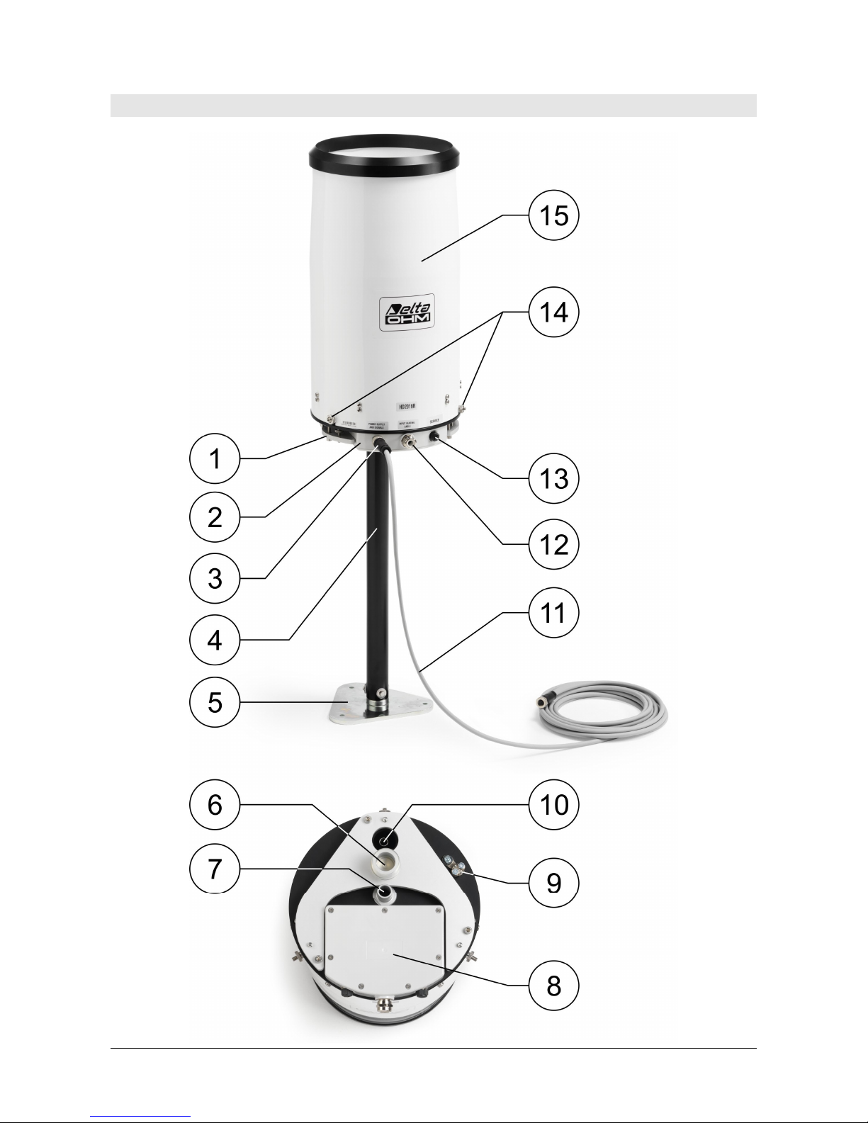
2DESCRIPTION

HD2016 - 5 - V1.4
1. Optional flange for the installation of the rain gauge raised above ground.
2. Electronic board housing.
3. M12 connector for the connection of the measuring circuit power supply and signals.
4. Optional support rod for the installation of the rain gauge raised above ground.
5. Optional flat base for fixing the support of the rain gauge raised above ground.
6. Place for the support rod.
7. Discharge of the rainfall collected.
8. Cover of the electronic board housing. To access the electronic board, loosen the 7 screws
that secure the cover.
9. Terminal for protective earth connection.
10. Overflow drain.
11. Optional cable for the connection of the measuring circuit power supply and signals.
12. Cable gland for the heater power supply.
13. Port reserved for technical service.
14. Screws for fixing the cylindrical cover.
15. Cylindrical cover.
HD2016 - 6 - V1.4
3INSTALLATION
The instrument must be installed in an open area (any close objects should be at a distance
equal to at least 4 times their height), away from buildings, busy roads, trees, etc., ensuring
the space over it is free from all objects which could obstruct rain measurements, and in an
easily accessible position for the filter to be cleaned periodically.
Although the rain gauge is equipped with features that allow reducing the effects of wind, for
the best measurement accuracy it is recommended to avoid installation in areas exposed to
turbulence (for example, do not install the instrument on the top of a hill, but on the side).
The rain gauge can be installed on the ground or raised 500 mm above the ground. Other sizes
above the ground are available on request.
For ground installation, three adjustable support feet, so that the instrument can be levelled
correctly, and holes for fixing to the floor have been provided.
For raised installations, a flange to be fastened to the base of the instrument, and on which
the support rod must be inserted, is provided. The rod may end with a flange so that it can be
fixed to the floor.
For the measurement to be correct, it is important that the rain gauge is placed perfectly lev-
elled; the base of the rain gauge is fitted with a bubble level.
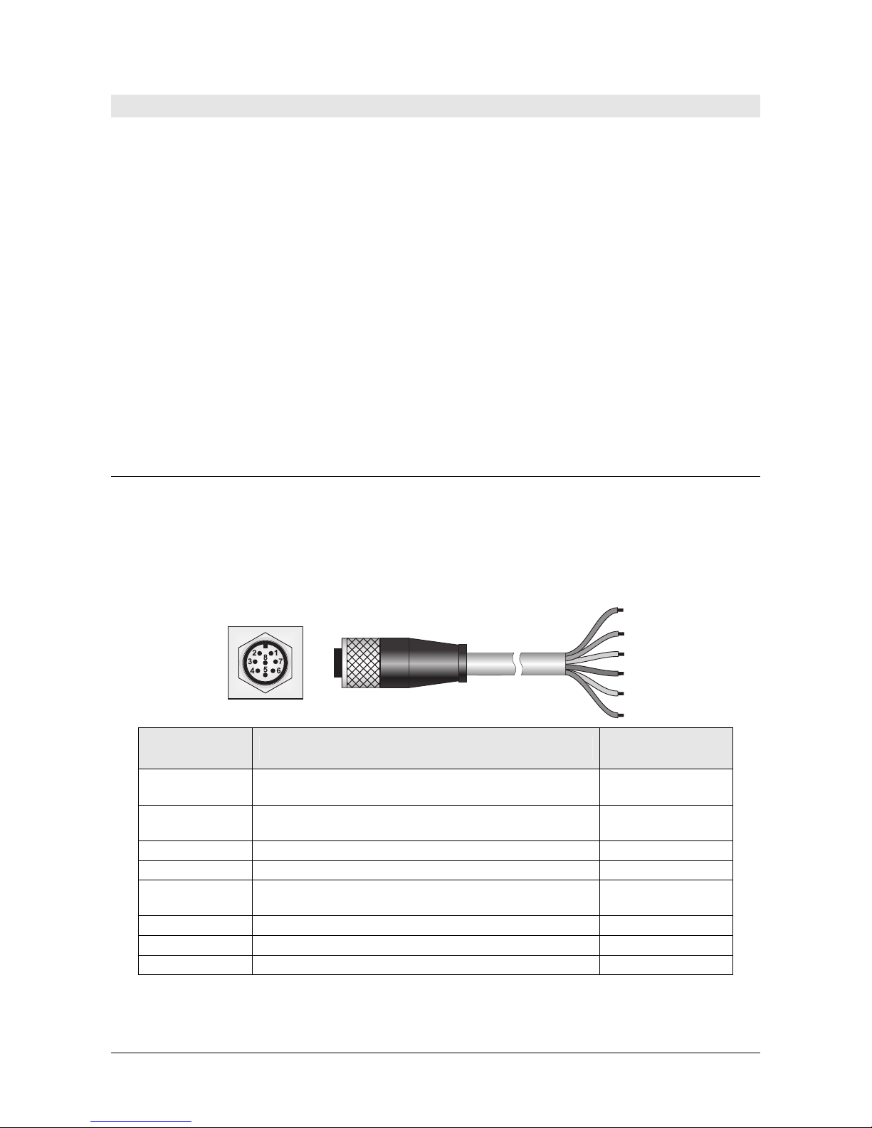
3.1 ELECTRICAL CONNECTIONS
The measuring circuit power supply and the outputs (RS485, SDI-12 or contact) are connected
via the male 8-pole M12 connector of the instrument (point 3 on page 4). Use a cable with a
female 8-pole M12 connector and 0.7 mm2(AWG 19) minimum wires section. Use a shielded
cable over long distances.Upon request, CP18… cables with 5 or 10 m standard length
are available (other lengths available upon request). The connections of the M12 connec-
tor and CP18… cable are listed below.
Connector
numbering Function CP18… cable
numbering
1 Measuring circuit power supply negative (GND)
SDI-12 output negative
12, 7, 6
(wires in parallel)
2 Measuring circuit power supply positive (+Vdc) 1, 2, 4
(wires in parallel)
3 Not connected
4 DATA – (RS485) 9
5 DATA + (RS485) or SDI-12 line
(depending on the setting of the switch SW1)
5
6 1st pole of the voltage-free contact 8
7 Not connected
8 2nd pole of the voltage-free contact 11
Fig. 3.1.1: M12 connector and CP18… cable
Connect the Protective Earth via the terminal under the base of the rain gauge (point 9
on page 4).
CP18… cable
Instrument
M12 male connector
HD2016 - 7 - V1.4
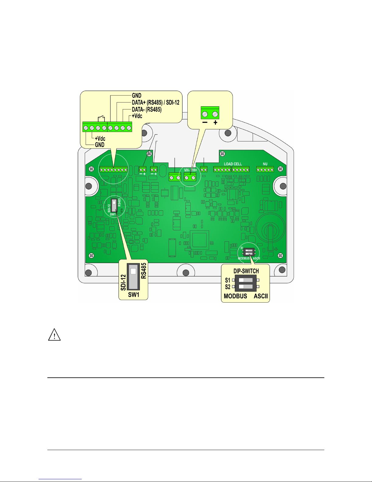
The heater power supply (only HD2016R) is connected directly to the internal terminal block.
Unscrew the cover of the electronic board (point 8 on page 4) and pass the cable through the
cable gland (point 12 on page 4). Use a cable with 2.5 mm2(AWG 13) minimum wires section.
The heater power supply is isolated from the measuring circuit.
The following figure shows the electronic board.
Fig. 3.1.2: electronic board
WARNING FOR VERSION HD2016R:
In order to prevent possible burns by coming into contact with the heater,
make sure that the heater is NOT powered when the cylindrical cover of the
rain gauge is removed for cleaning or maintenance operations.
3.2 CHOOSING THE DIGITAL OUTPUT AND THE PROTOCOL
The selection of the type of digital output is done by means of the switch SW1 on the electronic
board. Set the switch toward the RS485 or SDI-12 indication depending on the desired output.
The switch is set at the factory toward the RS485 indication (unless otherwise requested).
The switch S1 of the DIP switch on the electronic board allows selecting the communication
protocol of the digital output at the instrument power-on. Set the switch S1 toward the MOD-
BUS indication to select the standard protocol (Modbus-RTU or SDI-12 depending on the digital
output selected with the switch SW1), or set the switch toward the ASCII indication to select
the ASCII proprietary protocol. If the standard protocol is selected, it is possible to switch to
the ASCII proprietary protocol while the instrument is operating as described in the paragraph
H
ea
t
er
power supply
Upper valve
Discharge valve
NTC
Heater
resistance
contact
output
HD2016 - 8 - V1.4
“ ASCII proprietary protocol ”. By default, the standard protocol is selected (Modbus-RTU or
SDI-12 depending on the digital output selected with the switch SW1).
The setting of the switch SW1 and the DIP switch are read only at instrument pow-
er-on, therefore they must be set before powering the instrument. The change of the
setting of the switch SW1 and the DIP switch while the instrument is powered has no effect
until the instrument is turned off and back on.
Note: the switch S2 of the DIP switch does not perform any function.
To change the other instrument settings, see the paragraph “ ASCII proprietary protocol ”.
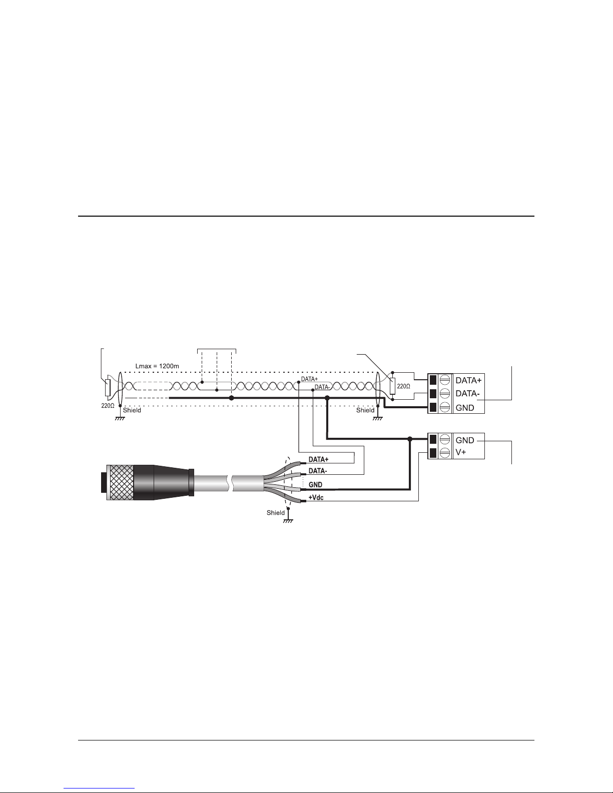
3.3 RS485 CONNECTION
In the RS485 connection, the instruments are connected through a twisted-pair shielded cable
for signals and a third wire for ground.
Line terminations should be placed at the two ends of the network. The rain gauge has a
built-in termination resistor, but it is not connected by default; if the rain gauge is at one end
of the network, you can connect the built-in termination resistor by using the command COt of
the ASCII proprietary protocol.
The RS485 output of the rain gauge is not isolated from the power supply.
Fig. 3.3.1: RS485 connection
The maximum number of devices that can be connected to the RS485 line (Bus) depends on the
load characteristics of the devices to be connected. The RS485 standard requires that the total
load does not exceed 32 unit loads; if the load is greater, divide the network into segments and
add a signal repeater between a segment and the successive one. Line termination should be
applied at both ends of each segment.
The maximum length of the cable depends on the transmission speed and the cable character-
istics. Typically, the maximum length is 1200 m. The data line should be kept separated from
any power lines in order to prevent interference with the transmitted signal.
Each instrument on the network is univocally identified by an address. Multiple transmitters
with the same address should not be placed in the network. Before connecting the in-
strument to the network, set the address and, if necessary, the communication parameters.
Power supply
CP18… cable
Termination
T
ermination
Data logge
r
input
Other sensors with
RS485 out
p
ut
HD2016 - 9 - V1.4
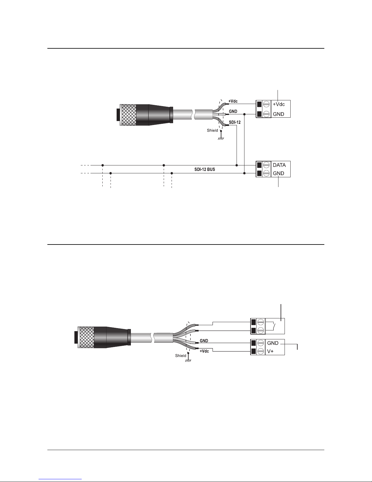
3.4 SDI-12 CONNECTION
More SDI-12 sensors can be connected in parallel. The distance between a sensor and the ac-
quisition system should not exceed 60 m. Before connecting the instrument to an SDI-12 net-
work containing other sensors, set the address by using the proper SDI-12 command.
Fig. 3.4.1: SDI-12 connection
3.5 CONTACT OUTPUT
The voltage-free contact output simulates the pulse output of a tipping bucket rain gauge. The
contact is isolated and is normally open. At 1 minute intervals, the output generates a pulse
train (TON ≈60 ms, TOFF ≈60 ms) as a function of the rainfall measured in the previous min-
ute. Each pulse corresponds to an amount of rainfall configurable from 0.001 to 1 mm/pulse
(default=0.2) by using the command CP0 of the ASCII proprietary protocol.
Fig. 3.5.1 – contact output connection
Power supply
CP18…
cable
Othe
r
SDI-12
sensor
Data logge
r
input
Othe
r
SDI-12
sensor
Power supply
CP18… cable
contact 1st
pole
Data logge
r
input
contact 2nd
pole
HD2016 - 10 - V1.4
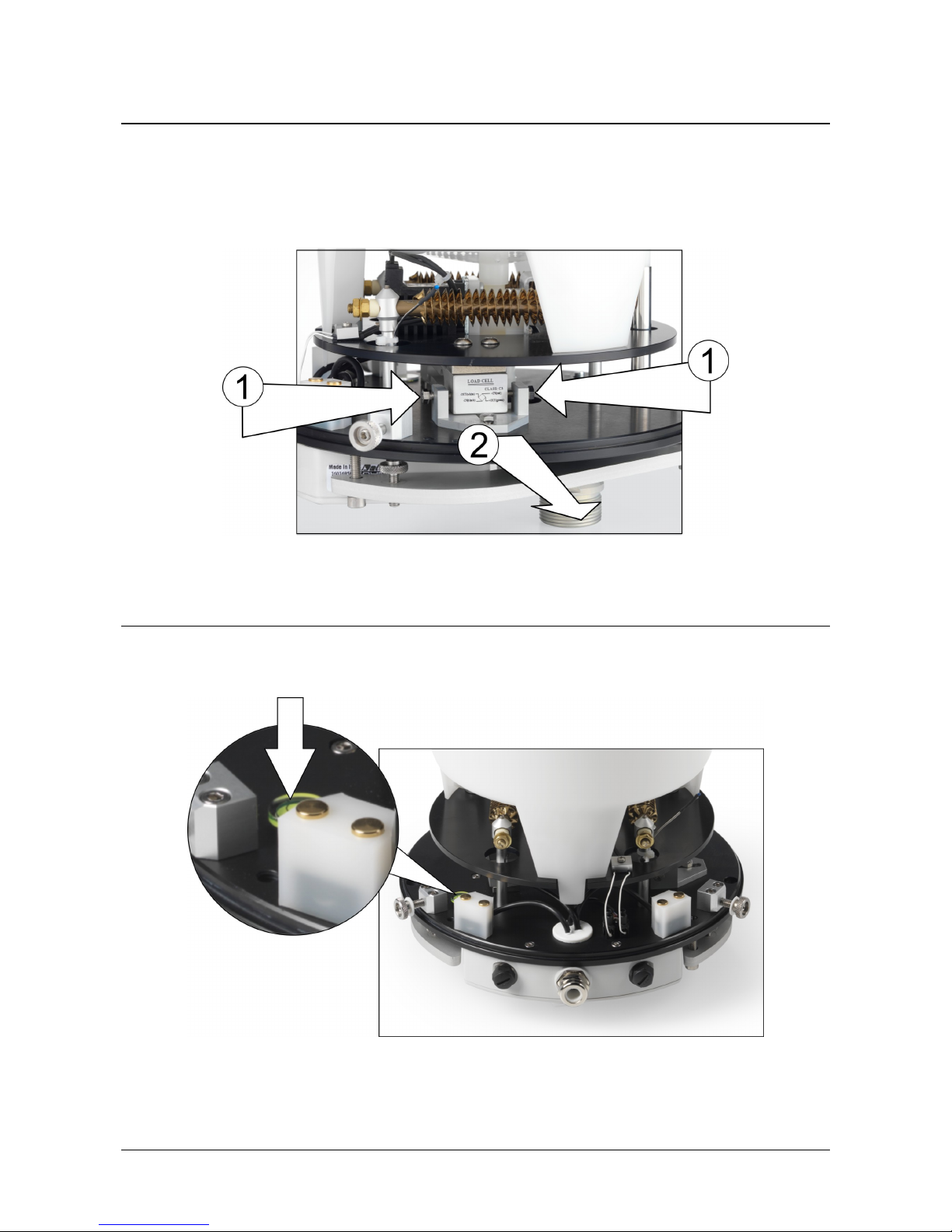
3.6 UNLOCKING THE LOAD CELL
The load cell is locked for the transport of the rain gauge. Loosen the three nuts (point 14 on
page 4) at the base of the cylindrical cover (point 15 on page 4) and remove the cylindrical
cover by pulling it upwards. Unlock the load cell located at the base of the rain gauge by loos-
ening the two screws on the sides of the cell and translating the locking support outward (fig.
3.6.1). Replace the cylindrical cover and tighten the 3 fixing nuts.
Fig. 3.6.1: unlocking the load cell
3.7 FIXING THE RAIN GAUGE
For the measurement to be correct, it is important that the rain gauge is placed perfectly lev-
elled; the base of the rain gauge is fitted with a bubble level.
Fig. 3.7.1: location of the bubble level
For ground installation, secure the three support feet to the base of the instrument. Adjust the
height of the feet so that the instrument is perfectly levelled. The instrument can be fixed to
the floor by using the holes provided in the feet, close to the adjustment screws.
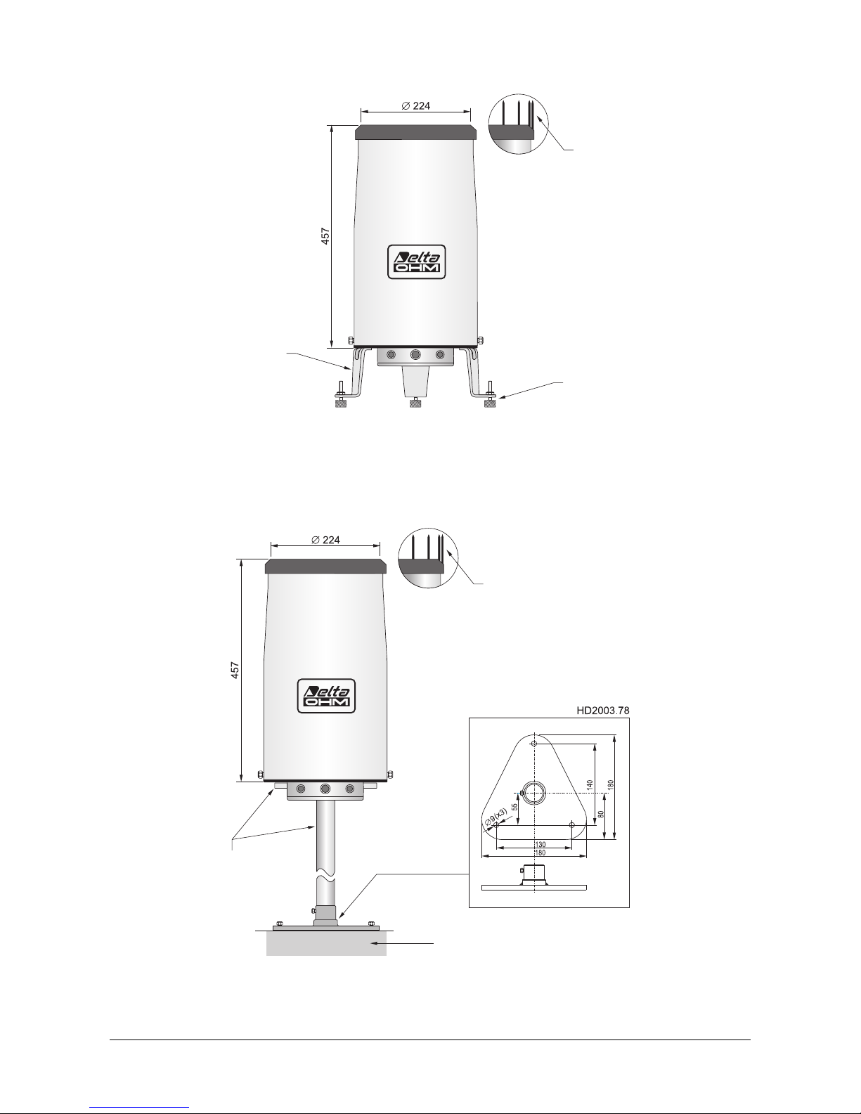
HD2016 - 11 - V1.4
Fig. 3.7.2: rain gauge ground installation
For raised installation, secure the flange of the HD2016.33K kit to the base of the instrument
and screw the support rod to the flange; the rod may end with a flange (HD2003.78) to be
fixed to the floor.
Fig. 3.7.3: rain gauge installation raised above ground
Bird dissuade
r
HD2016.33K
(flange +
support rod)
Flat
base
Floo
r
Bird dissuade
r
Feet
Adjustement screws
for levelling

HD2016 - 12 - V1.4
4ASCII PROPRIETARY PROTOCOL
The ASCII proprietary protocol is mainly used to set the operating parameters of the instru-
ment by sending serial commands from a PC. The protocol can be used both with RS485 and
SDI-12 physical interface.
The rain gauge should be connected to the PC by using a converter from RS485 or SDI-12
(depending on the rain gauge output used) to USB or RS232C (depending on the PC port
used). The use of the RS48 cable incorporating an RS485/USB converter is recommended. If a
USB converter is used, it is necessary to install the relevant USB drivers in the PC.
NOTES ON THE INSTALLATION OF UNSIGNED USB DRIVER:before installing unsigned USB driver into operating sys-
tems starting from Windows 7, it is necessary to restart the PC by disabling the driver signing request. If the
operating system is 64-bit, even after installation the request of driver signing have to be disabled each time
the PC is restarted.
The ASCII proprietary protocol can be activated both at instrument power-on and while the in-
strument is operating with the Modbus-RTU or SDI-12 protocols.
In order to activate the ASCII proprietary protocol at the rain gauge power-on, the DIP switch
S1 on the electronic board must be set to OFF (toward the ASCII indication, see the figure
3.1.2 on page 7) before turning the instrument on. If activated at power-on, the protocol op-
erates with the following communication parameters:
•Baud Rate = 57600
•Data bits = 8
•Parity = None (N)
•Stop bits = 1
•Flow control = None
If the rain gauge is powered with the DIP switch S1 set to ON (toward the MODBUS indication
on the electronic board), the Modbus-RTU or SDI-12 protocol, depending on the physical inter-
face used, is activated by default. In this case, the ASCII proprietary protocol can be activated
without turning the rain gauge off and without changing the setting of the DIP switch S1 by the
following procedure:
1. In the PC, start a serial communication program (many free programs suitable for the pur-
pose can be found on the Internet), then set the COM port number to which the instrument is
connecting and the communication parameters with which the instrument is operating
(19200 8E1 by default for RS485 Modbus-RTU, 1200 7E1 for SDI-12).
2. Send the command ||| (sequence of three 124 decimal code ASCII characters followed by
the Enter key). The instrument replies with @.
3. Within 10 seconds from the reply of the instrument, send the command @(64 decimal
code ASCII character followed by the Enter key). The instrument replies with address: &,
where nnn is the address of the instrument (if the instrument does not receive the com-
mand @ within 10 seconds, the ASCII proprietary protocol is not activated; in this case, re-
peat from point 2). The ASCII proprietary protocol is now active keeping the communication
parameters of the previous protocol (therefore, it is not necessary to change the settings of
the serial communication program).
To disable the ASCII proprietary protocol after use and return to the previous protocol, send
the command #(or power cycle the instrument).
After activation of the ASCII proprietary protocol, the serial commands given below can be
sent.
To change the rain gauge parameters, the serial command CAL USER ON must be sent first
(the instrument replies with address: USER ENABLED!). In order to cancel the command
CAL USER ON, send the command CAL END (the instrument replies with address: LOCKED).
The command CAL USER ON is automatically disabled after 5 minutes of inactivity. If the set-
tings should be only read, the command CAL USER ON is not required.
HD2016 - 13 - V1.4
Instrument general information
Command Reply Description
P0 address: & Ping
G0 HD2016 Model
G2 SN=number Serial number
G3 Firm. Ver.=version Firmware version
G4 Firm. Date=yyyy/mm/dd Firmware date
GD F cal:yyyy/mm/dd hh:mm:ss Factory calibration date
Reservoir discharge
Command Reply Description
CD address: & Runs the reservoir discharge cycle
CVL address: state&Changes the state of the reservoir discharge valve:
state=Opened ⇒valve has been opened
state=Closed ⇒valve has been closed
COa address: & Activates the discharge after 20 minutes from the
end of the rainfall if the reservoir filling percentage is
greater than or equal to 80% (2400 cc)
COb address: & Activates the discharge after 20 minutes from the
end of the rainfall if the reservoir filling percentage is
greater than or equal to 10% (300 cc)
RDE address: delay Reads the delay time before running the discharge at
the end of a rainfall (default = 20 minutes)
CDE nnn address: & Activates the discharge after nnn minutes (20 ≤nnn ≤
480) from the end of the rainfall if the reservoir filling
percentage is greater than the set threshold
RTE address: percentage Reads the reservoir filling percentage that enables the
discharge (default = 10% ⇒300 cc)
CTE nn address: & Activates the discharge (after the delay time set) if
the reservoir filling percentage is greater than nn %
(1 ≤nn ≤99)
Note: the discharge takes place normally at the end of a rainfall after the delay time set; if the reservoir
should overfill during a rainfall, the discharge will take place during the rainfall and the upper retention valve
will close to maintain the current rainfall in the upper part of the rain gauge; at the end of the discharge
phase, the rainfall collected in the upper part of the rain gauge will be discharged in the main reservoir and
weighted.
Upper retention valve
Command Reply Description
ROv address: state Reads the enabling state of the upper retention valve:
state=0⇒valve is not enabled
state=1⇒valve is enabled
COv naddress: & Enables/disables the use of the upper retention valve:
n=0⇒disable ; n=1⇒enable
CVH address: state&Change the state of the upper retention valve:
state=Opened ⇒valve has been opened
state=Closed ⇒valve has been closed
HD2016 - 14 - V1.4
Heater
The HD2016R rain gauge has a temperature sensor that detects the internal temperature of the instru-
ment (not the air temperature). The heater is activated when the internal temperature falls below the
value set with the command CTL (default 4 °C) and is switched off when the internal temperature rises
above the value set with the command CTH (default 10 °C).
Command Reply Description
RTH address: temperature Reads the heater deactivation temperature
(default = 10.0 °C)
CTH nn.d address: & Sets the heater deactivation temperature to the value
nn.d
(activation temperature ≤nn.d ≤10.0 °C)
RTL address: temperature Reads the heater activation temperature
(default = 4.0 °C)
CTL nn.d address: & Sets the heater activation temperature to the value
nn.d
(4.0 °C ≤nn.d ≤deactivation temperature)
RTD address: state Reads the heater enabling state:
state=Enabled ⇒heater is used
state=Disabled ⇒heater is not used
CTD naddress: & Enables/disables the use of the heater:
n=0⇒disable ; n=1⇒enable
CHS address: state&Changes the activation state of the heater:
state=On ⇒heater has been switched on
state=Off ⇒heater has been switched off
Resolution of contact output
Command Reply Description
RP0 address: resolution Reads the resolution, in mm/pulse, of the contact
output (default = 0.200 mm/pulse)
CP0 n.ddd address: & Sets the resolution of the contact output to the value
n.ddd mm/pulse (max. 1 mm/pulse)
Counters reset
Command Reply Description
CS address: & Resets the partial rainfall value
CLR address: & Resets all the counters
It must be run before the total weight counter reaches
the maximum value 999,999,999 mg
RS485 settings
Command Reply Description
ROt address: state Reads the connection state of the termination resistor
of the RS485 output:
state=0⇒termination resistor not connected
state=1⇒termination resistor connected
COt naddress: & Connect/disconnect the termination resistor of the
RS485 output: n=0⇒disconnect ; n=1⇒connect
RMA address: address address Reads the Modbus address (default = 1)
CMA nnn address: & Sets the Modbus address to nnn (1…247)
RMB address: baud rate index MB baud Reads the Modbus Baud Rate:
Baud rate index=0⇒9600
Baud rate index=1⇒19200 (default)
CMB naddress: & Sets the Modbus Baud Rate of index n:
n=0⇒9600 ; n=1⇒19200
HD2016 - 15 - V1.4
Command Reply Description
RMP address: mode index MB mode Reads the Modbus transmission mode:
mode index=0⇒8N1
mode index=1⇒8N2
mode index=2⇒8E1 (default)
mode index=3⇒8E2
mode index=4⇒8O1
mode index=5⇒8O2
(N=no parity, E=even parity, O=odd parity)
CMP naddress: & Sets the Modbus transmission mode:
n=0⇒8N1 ; n=1⇒8N2 ; n=2⇒8E1
n=3⇒8E2 ; n=4⇒8O1 ; n=5⇒8O2
(N=no parity, E=even parity, O=odd parity)
RMW address: delay index MB Tx delay Reads the receiving mode after the Modbus trans-
mission:
delay index=0⇒Violate protocol and go in receiving
mode right after Tx
delay index=1⇒Respect protocol and wait for 3.5
characters after Tx (default)
CMW naddress: & Sets the receiving mode after the Modbus transmis-
sion:
n=0⇒Violate protocol and go in receiving mode
right after Tx
n=1⇒Respect protocol and wait for 3.5 characters
after Tx
Printing the measures
Command Reply Description
SR naddress: measured value Single print of the measure of index n:
n=0 ⇒Status register content in hexadecimal
n=2 ⇒Partial rainfall, in µm, from the last reading
command
n=4 ⇒Total rainfall in µm
n=6 ⇒Partial rainfall, in µm, from the last reset
command
n=8 ⇒Average rainfall rate, in µm/min, calculated
in the last minute
n=10 ⇒Average rainfall rate, in µm/h, calculated in
the last hour
n=12 ⇒Rain gauge internal temperature in °C
n=14 ⇒Rainfall total weight (Pmg) in mg (*)
n=16 ⇒Rainfall total weight, in mg, considering the
evaporation (Wmg) (*)
n=18 ⇒Weight, in mg, of the current reservoir
content (Tmg) (*)
n=20 ⇒Partial rainfall, in mils, from the last reading
command
n=22 ⇒Total rainfall in mils
n=24 ⇒Partial rainfall, in mils, from the last reset
command
n=26 ⇒Average rainfall rate, in mils/min, calculated
in the last minute
n=28 ⇒Average rainfall rate, in mils/h, calculated
in the last hour
n=30 ⇒Rain gauge internal temperature in °F
(*) For details on weight measurements, please see
the paragraph “Notes on weight measurements”.
RR naddress: measured value Continuous print (once per second) of the measure of
index n (see the command SR for the indexes)
HD2016 - 16 - V1.4
Command Reply Description
S0 String with 16 fields Single print of all the measures:
campo 1 ⇒& followed by a control code
campo 2 ⇒Filling percentage of the rain gauge
reservoir
campo 3 ⇒Weight, in mg, of the current reservoir
content (Tmg) (*)
campo 4 ⇒Rainfall total weight, in mg, considering
the evaporation (Wmg) (*)
campo 5 ⇒Rainfall total weight (Pmg) in mg (*)
campo 6 ⇒Partial rainfall, in µm, from the last reset
command
campo 7 ⇒Average rainfall rate, in µm/min, calcu-
lated in the last minute
campo 8 ⇒Average rainfall rate, in µm/h, calculated
in the last hour
campo 9 ⇒Reservoir status (Evap if in evaporation,
Rain if in precipitation) followed by * (va-
lid data) or ! (invalid data)
campo 10 ⇒Indicates how long the status reported in
the previous field has been active
campi 11…15 ⇒Confidential information
campo 16 ⇒Internal temperature in °C
(*) For details on weight measurements, please see
the paragraph “Notes on weight measurements”.
R0 String with 16 fields Continuous print (once per second) of all the meas-
ures (see the command S0 for the fields)
ST address: & voltage status_register Prints the supply voltage in Volt and the content of
the status register in hexadecimal
SS address: status_register Prints the content of the status register in hexadeci-
mal
HD2016 - 17 - V1.4
5MODBUS-RTU PROTOCOL
For enabling the Modbus-RTU protocol, set on the electronic board, before powering the in-
strument, the DIP switch S1 to ON, toward the MODBUS indication, and the switch SW1 to-
ward the RS485 indication (see the figure 3.1.2 on page 7).
In Modbus-RTU mode, the instrument sends the detected measurements only if specifically re-
quested by the PC, PLC or data logger.
The default communication parameters are:
•Baud Rate = 19200
•Data bits = 8
•Parity = Even (E)
•Stop bits = 1
•Flow control = None
The communication parameters can be changed by using the appropriate serial commands of
the ASCII proprietary protocol or, alternatively, directly with Modbus commands by changing
the value of the Holding Registers described later.
The function code 04h (Read Input Registers) allows reading the values measured by the in-
strument. The following table lists the Input Registers available.
Modbus Input Registers
Register
address Datum Format
0 Content of the status register 16-bit integer
1 Not used 16-bit integer
2,3 Partial rainfall, in µm, from the last reading command 16-bit integer
4,5 Total rainfall in µm 16-bit integer
6,7 Partial rainfall, in µm, from the last reset command 16-bit integer
8,9 Average rainfall rate, in µm/min, calculated in the last minute 16-bit integer
10,11 Average rainfall rate, in µm/h, calculated in the last hour 16-bit integer
12,13 Rain gauge internal temperature in °C 16-bit integer
14,15 Rainfall total weight (Pmg) in mg (*) 16-bit integer
16,17 Rainfall total weight, in mg, considering the evaporation (Wmg) (*) 16-bit integer
18,19 Weight, in mg, of the current reservoir content (Tmg) (*) 16-bit integer
20,21 Partial rainfall, in mils, from the last reading command 16-bit integer
22,23 Total rainfall in mils 16-bit integer
24,25 Partial rainfall, in mils, from the last reset command 16-bit integer
26,27 Average rainfall rate, in mils/min, calculated in the last minute 16-bit integer
28,29 Average rainfall rate, in mils/h, calculated in the last hour 16-bit integer
30,31 Rain gauge internal temperature in °F 16-bit integer
(*) For details on weight measurements, please see the paragraph “Notes on weight measurements”.
The measures are signed 32-bit integer values. Two consecutive 16-bit registers must be ac-
cessed to read a measure. The register with lower address (for example the register with ad-
dress 12 for the temperature in °C) contains the most significant bits.
Some operating parameters of the instrument can be changed directly with Modbus commands
by setting the value of the Holding Registers with the function code 06h (Write Single Register)
or 10h (Write Multiple Registers). The following table lists the Holding Registers available.
HD2016 - 18 - V1.4
Modbus Holding Registers
Register
address Datum Format
0 Indicator of the correct execution of the last writing command.
If 0, the command has been executed correctly.
If 1, command execution errors occurred.
16-bit integer
1 Indicator of the correct permanent storage of the parameters.
If 0, the parameters have stored correctly.
If 1, storage errors occurred.
16-bit integer
2 Content of the status register 16-bit integer
8 Heater enabling/disabling.
Write A500h to enable the use of the heater.
Write A501h to disable the use of the heater.
16-bit integer
9 Reset of all the counters.
Write A55Ah to reset the counters.
16-bit integer
10 Reset of the partial rainfall value.
Write A55Bh to reset the value.
16-bit integer
11 Reservoir discharge cycle.
Write A55Ah to run the discharge cycle.
16-bit integer
100 Modbus address (from 1 to 247, default=1). 16-bit integer
101 Modbus Baud Rate.
If 0, the Baud Rate is 9600. If 1, the Baud Rate is 19200 (default).
16-bit integer
102 Modbus transmission mode.
0⇒8N1, 1⇒8N2, 2⇒8E1 (default), 3⇒8E2, 4⇒8O1, n=5⇒8O2
(N=no parity, E=even parity, O=odd parity)
16-bit integer
103 Receiving mode after the Modbus transmission (Tx).
0⇒Violates the protocol and goes immediately in reception mode after Tx
1⇒Respects the protocol and waits for 3.5 characters after Tx (default)
16-bit integer
In order to check whether the last writing operation has been completed successfully, verify
that the Holding Register with address 0 contains 0 by using the function 03h (Read Holding
Registers).
The 06h and 10h writing functions change only the value of the parameters in the RAM mem-
ory, the change is therefore cancelled in case of power supply failure in the instrument. For
making the change permanent, write the hexadecimal value FF00 in the Coil with ad-
dress 2 by using the 05h function code (Write Single Coil). The command 05h must
be sent within 10 seconds from the last 06h or 10h command.
Modbus Coils
Register
address Datum
2 Permanent storage of the parameters.
In order to check whether the permanent storage has been completed successfully, verify that
the Holding Register with address 1 contains 0, by using the function 03h (Read Holding Regis-
ters).
HD2016 - 19 - V1.4
6SDI-12 PROTOCOL
For enabling the SDI-12 protocol, before powering the instrument set on the electronic board
the DIP switch S1 to ON, toward the MODBUS indication, and the switch SW1 toward the
SDI-12 indication (see the figure 3.1.2 on page 7).
The instrument is in compliance with the version 1.3 of the protocol. The communication pa-
rameters of the protocol are:
•Baud Rate = 1200
•Data bits = 7
•Parity = Even (E)
•Stop bits = 1
Communication with the instrument is performed by sending a command in the following format:
<Address><Command>!
With <Address> = address of the instrument the command is sent to
<Command> = type of operation requested to the instrument
The instrument reply is as follows:
<Address><Data><CR><LF>
With <Address> = address of the replying instrument
<Data> = information sent by the instrument
<CR> = ASCII character Carriage Return
<LF> = ASCII character Line Feed
The table below shows the available SDI-12 commands. For consistency with the documenta-
tion of the SDI-12 standard, the instrument address is indicated in the table with the letter a.
The rain gauge leaves the factory with address preset to 0. The address can be changed by us-
ing the proper SDI-12 command reported in the table.
SDI-12 commands
Command Instrument reply Description
a! a<CR><LF> Verifies the presence of the in-
strument.
aI! allccccccccmmmmmmvvvssssssss<CR><LF>
with:
a = address of the instrument (1 character)
ll = SDI-12 compliant version (2 characters)
cccccccc = manufacturer (8 characters)
mmmmmm = instrument model (6 characters)
vvv = firmware version (3 characters)
ssssssss = serial number (8 characters)
⇒Example of reply:
013DeltaOhmHD2016A0013201518
with:
0 = instrument address
13 = SDI-12 version 1.3 compliant
DeltaOhm = manufacturer’s name
HD2016 = instrument model
A00 = firmware version
13201518 = serial number
Requests for information from
the instrument.
aAb!
Where:
b = new
address
b<CR><LF>
Note: if the b character is not an acceptable address, the
instrument replies with a instead of b.
Modification of the instrument
address.
HD2016 - 20 - V1.4
Command Instrument reply Description
?! a<CR><LF> Request of the address of the
instrument. If more than one
sensor is connected to the bus,
a conflict occurs.
TYPE M(START MEASUREMENT)AND TYPE C(START CONCURRENT MEASUREMENT)COMMANDS
Total rainfall (mm) and rainfall rate
aM!
aC!
atttn<CR><LF>
with: ttt = number of seconds necessary for the instrument
to make the measure available (3 characters)
n = number of detected variables (1 character for
aM!, 2 characters for aC!)
Note: ttt = 000 means that datum is immediately available.
Request to detect:
- total rainfall (mm)
- rainfall rate
aD0! a+SR+IM+IH+RT<CR><LF>
with:
SR= content of the status register in hexadecimal
IM= average rainfall rate, in mm/min, calculated in the
last minute
IH= average rainfall rate, in mm/h, calculated in the last
hour
RT= total rainfall in mm
Reads:
- total rainfall (mm)
- rainfall rate
Rainfall (mm), rainfall rate and temperature (°C)
aM1!
aC1!
atttn<CR><LF>
with: ttt = number of seconds necessary for the instrument
to make the measure available (3 characters)
n = number of detected variables (1 character for
aM1!, 2 characters for aC1!)
Note: ttt = 000 means that datum is immediately available.
Request to detect:
- rainfall (mm)
- rainfall rate
- temperature (°C)
aD0! a+SR+IH+RT<CR><LF>
with:
SR= content of the status register in hexadecimal
IH= average rainfall rate, in mm/h, calculated in the last
hour
RT= total rainfall in mm
Reads:
- total rainfall (mm)
- rainfall rate
aD1! a+RP+IM+T <CR><LF>
with:
RP= partial rainfall, in mm, from the last reset command
IM= average rainfall rate, in mm/min, calculated in the
last minute
T = rain gauge internal temperature in °C
Reads:
- partial rainfall (mm)
- rainfall rate
- temperature (°C)
Table of contents
Other Delta OHM Industrial Equipment manuals


Popular Industrial Equipment manuals by other brands


Unitary products group
Unitary products group PS8 installation manual

Siemens
Siemens Simatic ET 200pro FC operating instructions

Schischek
Schischek InMax Revolution manual

Swann
Swann AMI Deltacon Power Operator's manual

Scheppach
Scheppach rs 350 Translation of original instruction manual

Astrea
Astrea Evolve AA20CRK Replacement guide


