Manual, Tool Changer, QC-201
Document #9620-20-B-201 Base Tool Changer-12
Pinnacle Park
1031 Goodworth Drive
Apex, NC 27539
Tel: 919.772.0115
Fax: 919.772.8259
www.ati-ia.com
B - 10
4. Maintenance
The tool changer and optional modules are designed to provide a long life with little
maintenance required.
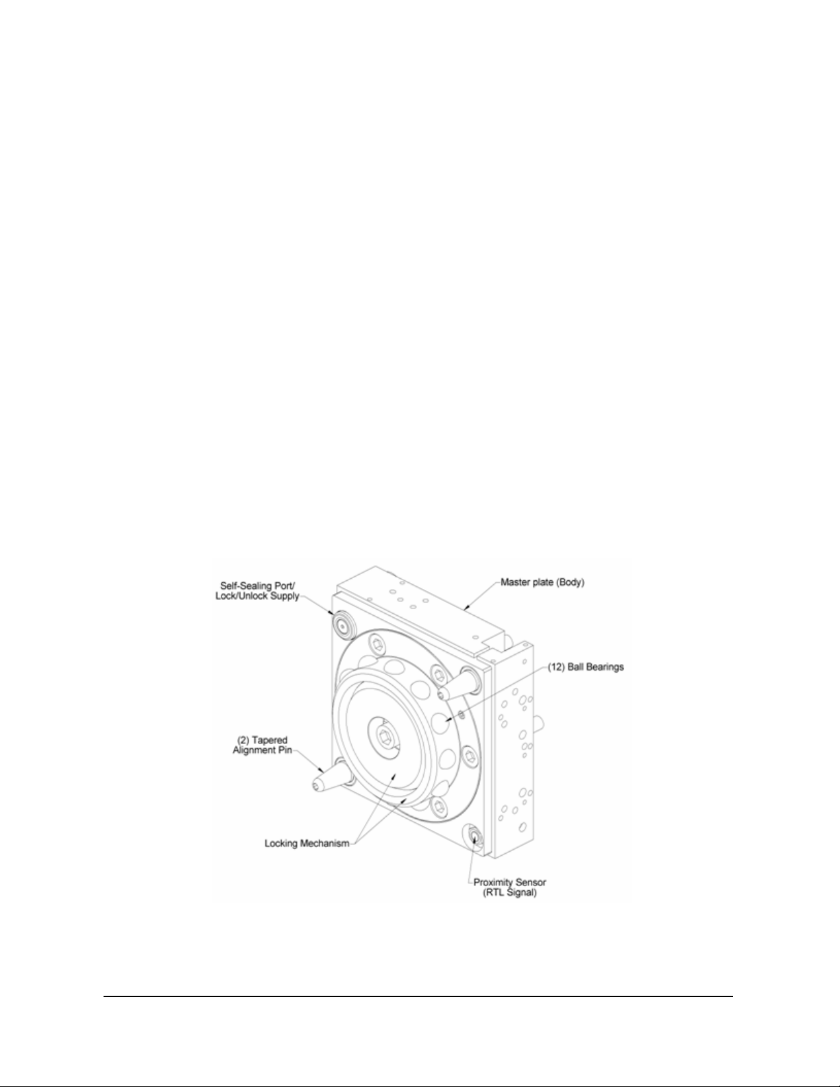
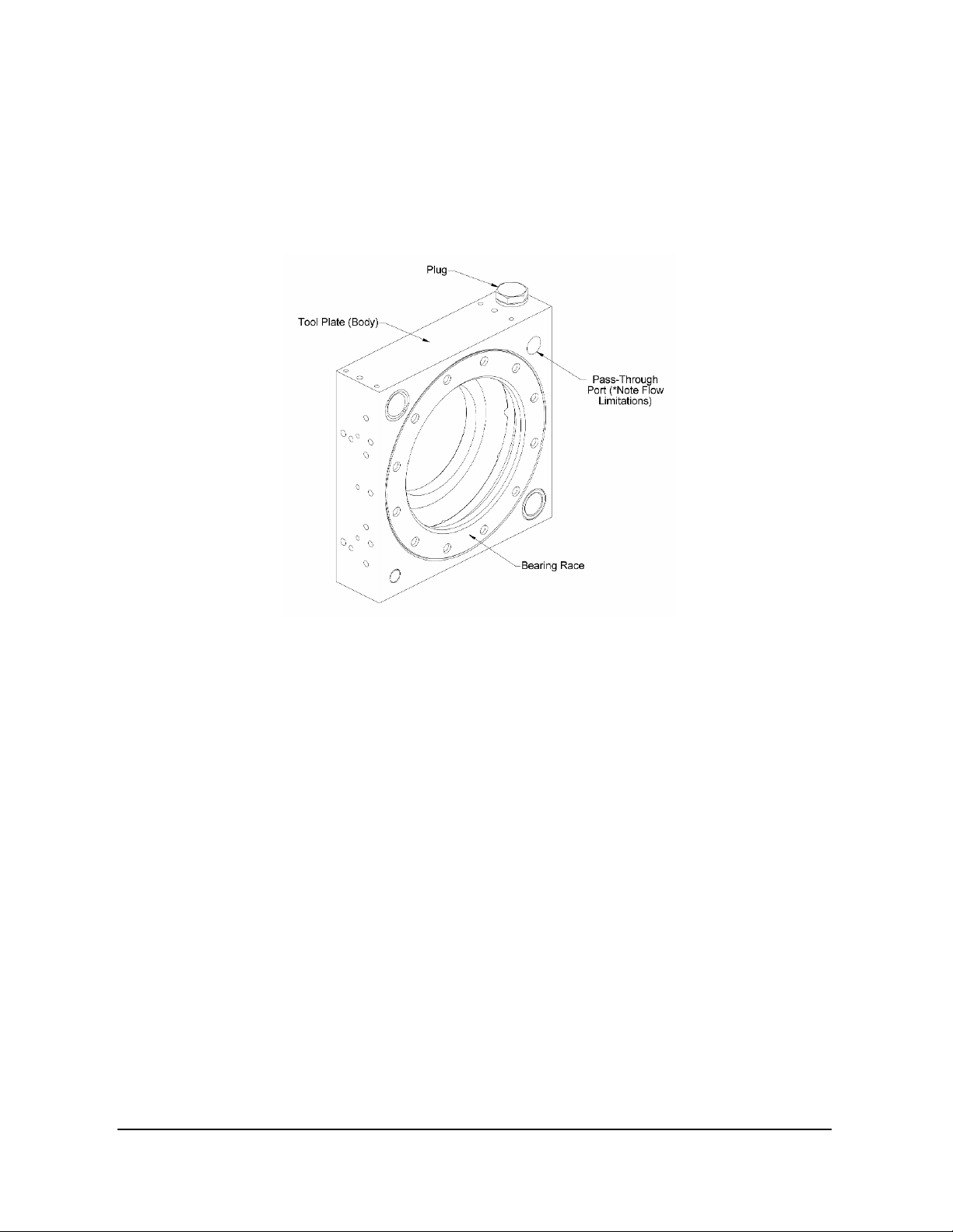
A visual inspection of the locking mechanism is recommended every 100,000 cycles or on a
semi-annual basis, whichever comes first. The ball bearings, alignment pins, bearing race and
alignment pin holes should be inspected for wear and lubrication. Component parts are to be
cleaned thoroughly prior to re-lubricating. A NLGI #2, lithium-based grease with
molybdenum disulfide additive is suggested for ball and alignment pin lubrication.
If alignment pin replacement is required the new alignment pins must be installed with a
torque of 60 in-lbs, and Loctite 242 or similar must be used.
An inspection of the tool stand and tool should be performed periodically for evidence of
wear, bending or other problems that could affect Master and Tool Plate alignment during
coupling and uncoupling.
Rubber bushings should be periodically inspected for wear, abrasion and cuts that can result
from improper handling.
If the tool changer is being used in dirty environments (e.g. welding or deburring applications)
care should be taken to limit the exposure of the tool changer. Unused Tool assemblies should
be covered to prevent debris from settling on the mating surface. Also, the Master Plate
assembly should be exposed for only a short period of time during tool change and down time.
In this instance the customer should determine a suitable inspection schedule.
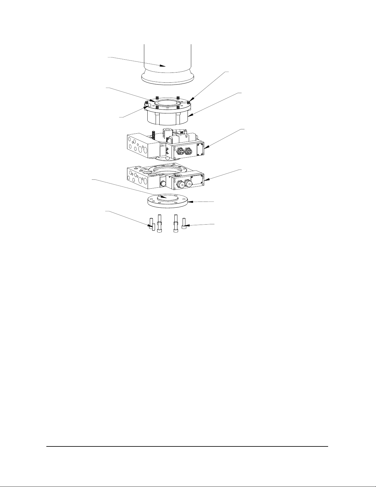
Detailed assembly drawings are provided in Section 8—Drawings of this manual.
4.1 Preventive Maintenance
The tool changer and optional modules are designed to provide a long life with regular
maintenance required.
A visual inspection and preventative maintenance schedule is provided in the table below
depending upon the application.
Detailed assembly drawings are provided in Section 8—Drawings of this manual.
ATTENTION: The cleanliness of the work environment strongly influences the trouble-free
operation of the changer. The dirtier the environment, the greater the need for protection
against debris. Protection of the entire EOAT, the master, the tool and all of the modules
may be necessary. Protective measures include the following: 1) Placement of tools stands
away from debris generators, 2) covers incorporated into the tool stands (see Section 2.3—
Tool Stand Design), and 3) guards, deflectors, air curtains, and similar devices built into the
ATTENTION: All tool changers are initially lubricated using MobilGrease® XHP222
Special grease. The end user must apply additional lubricant to the locking
mechanism components and alignment pins prior to start of service (See Section
4.2—Cleaning, Lubrication, Adjustment and Replacement). Tubes of lubricant for this
purpose are shipped with every tool changer. Note: MobilGrease® XHP222 Special is
a NLGI #2 lithium complex grease with molybdenum disulfide.