Delta OHM HD2307.0 User manual


HD2307 - 2 - V1.7
CON TEN TS
GEN ERAL CH ARACTERI STI CS............................................................................................................................ 3
DESCRI PTI ON OF TH E FUN CTI ON S ............................................................................................................... 6
TH E PROGRAM M I NG M EN U ................................................................................................................................ 9
PROBES AN D M EASUREM EN TS ....................................................................................................................... 10
TEMPERATURE MEASUREMENT ................................................................................................................................... 10
CALI BRATI ON OF THE PROBE...................................................................................................................................... 10
CALI BRATI ON SEQUENCE –INSTRUMENT ON LI NE WI TH THE PROBE(S): .............................................................. 11
CONNECTI NG THE TP47 CONNECTOR FOR THE 3AND 4WI RE PT100 AND 2OR 4- WI RE PT1000
PROBES:....................................................................................................................................................................... 12
DIRECT CONNECTION OF 4WIRE PT100 SENSORS.......................................................................................................... 14
W ARN I N GS AN D OPERATI N G I N STRUCTI ON S ..................................................................................... 15
I N STRUM EN T SI GN ALS AN D FAU LTS ......................................................................................................... 16
I NSTRUM EN T STORAGE...................................................................................................................................... 16
LOW BATTERY W ARN I N G AN D BATTERY REPLACEM EN T ............................................................... 17
WARNI NG ABOUT BATTERY USE ................................................................................................................................. 17
NOTES ABO UT W ORKI N G AN D OPERATI VE SAFETY .......................................................................... 18
I N STRUM EN T TECH N I CAL CH ARACTERI ST I CS ..................................................................................... 19
TECHNI CAL I NFORMATI ON ON THE RTD THERMOMETER ......................................................................................... 19
TECHNI CAL DATA OF PROBES AND MODULES I N LI NE WI TH THE I NSTRUMENT....................................................... 20
TEMPERATURE PROBES PT100 SENSOR USI NG SI CRAM MODULE ................................................................... 20
Pt 100/ Pt 1000 probes wit h TP47 connect or wit hout SI CRAM m odule .......................................... 20
ORD ERI N G CODES ................................................................................................................................................. 21

HD2307 - 3 - V1.7
GEN ERAL CHARACTERI STI CS
The RTD Therm om et er Model H D2 3 0 7 .0 is a portable inst rum ent t hat m easures t he
t em perat ure.
I t is fit ted with a large LCD display for ex cellent v isualizat ion of t he m easured dat a.
The RTD Therm om et er Model H D2 3 0 7 .0 m easures t he t em perat ure using im m ersion,
penet ration, contact or air probes. I n this case, the sensor can be a 3 or 4 w ire Pt100,
or 2 or 4 wire Pt 1000.
The probes are fit ted with t he autom at ic det ection m odule, w it h t he fact ory calibr at ion
set t ings already being m em orized inside.
The unit s of m easurem ent are t he follow ing:
1. ° C Celsius degrees
2. ° F Fahrenheit degrees
Using t he Max, Min and Av g funct ion of t his inst rum ent respect iv ely obtains t he
m axim um , m inim um or average values.
Ot her available funct ions ar e:
•t he r elat ive m easurem ent REL;
•the HOLD function;
•the autom atic turning off which can also be disabled.
HD2307 - 4 - V1.7
RTD Therm om et er
H D 2 3 0 7.0

HD2307 - 5 - V1.7
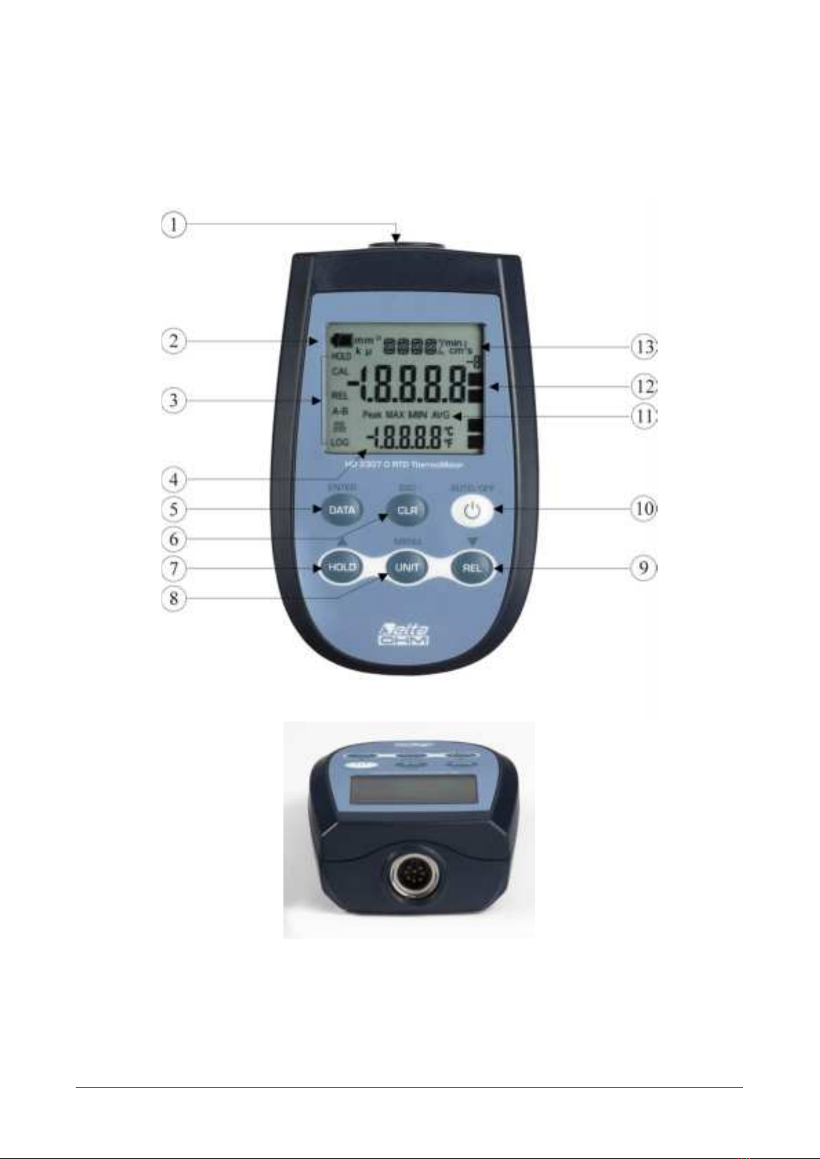
HD2 3 0 7 .0
1. I nput for probes, 8-pole DI N45326 connector.
2. Bat tery sym bol: displays t he bat tery charge level.
3. Funct ion indicators.
4. Secondary display line.
5. DATA/ EN TER key: during norm al operat ion displays t he m ax im um ( MAX) , t he
m inim um ( MI N) and t he av erage ( AVG) of current m easurem ent s; in t he m enu,
confirm s the current selection.
6. CLR/ ESC key: during norm al operat ion reset s t he m axim um , t he m inim um and
t he average of current m easurem ent s; in the m enu, it reset s t he value set wit h the
arrows.
7. HOLD / key: freezes t he m easurem ent dur ing nor m al operat ion; in the m enu,
increases t he current value.
8. UN I T/ MEN U key: it allows select ion of t he unit of m easurem ent; when pressed
toget her with the DATA key, it allows to open t he m enu.
9. REL/ key: during norm al oper at ion enables t he relat ive m easurem ent ( displays
the difference bet ween t he current value and the logged value when the key is
pressed); in t he m enu, decreases the current value
10.ON -OFF/ AUTO-OFF key: t urns t he inst rum ent on and off; when pressed together
with the HOLD key, disables the AutoPowerOff funct ion.
11.MAX ( m ax im um value) , MI N ( m in im um v alue) and AV G ( average value) sy m bols.
12.Main display line.
13.Line for sym bols and com m ents.
HD2307 - 6 - V1.7
DESCRI PTI ON OF THE FUN CTI ON S
The keyboard of the RTD Therm om eter Model H D2 3 0 7 .0 is com posed of double-
funct ion keys. The funct ion on t he key is t he "m ain funct ion", w hile t he one above t he
key is the " secondary funct ion".
When t he inst rum ent is in st andard m easurem ent m ode, t he m ain funct ion is act ive.
I n t he m enu, t he secondary funct ion is enabled; press the D ATA+ U N I T keys together
t o open t he m enu.
The pr essing of a key is accom pan ied by a short confir m at ion " beep": a longer " beep"
sounds if the wrong key is pressed. Each key specific funct ion is descr ibed in det ail
below.
This key has t wo functions:
•ON / OFF: press this key t o turn t he instrum ent on and off.
The t urning on enables all display segm ent s for a few seconds, st art s an Au t o-t e st
including the det ect ion of t he probe connect ed to the input , and set s t he instrum ent
ready for norm al m easurem ent .
•AUTO/ OFF: the Au t o Po w e r O ff funct ion can be disabled by sim ult aneously
pressing t his key and t he " HOLD" key when t urning the inst rum ent on.
During turning on, should no probes be connect ed, t he "NO_ PRBE_ SER_ N UM "
m essage is displayed in t he line for sym bols for a few seconds, and in t he m ain line a
series of dashes appears while the " ERR" m essage replaces the t em perat ure.
When t he probe is insert ed int o a funct ioning inst rum ent , t he " N EW _ PROB_ DET"
( New probe det ect ed) m essage appears: as t he dat a ar e captured upon t urning t he
inst rum ent on, it is necessary to turn it off and on again.
Ca u t ion ! Replace t he probes when t he inst rum ent is off.
ON -OFF and AUTO-OFF

HD2307 - 7 - V1.7
The inst rum ent has an AutoPowerOff funct ion t hat autom at ically t ur ns the inst rum ent
off after about 8 m inutes if no key is pressed during the intervening t im e.
Press sim ultaneously t he ON / OFF key and the H OLD key t o disable t h is funct ion.
I n t his case, rem em ber t o t urn t he inst rum ent off using t he ON / OFF key: disabling of
t he autom at ic t urning off is shown by t he blinking bat tery sym bol.
The DATA key is used for the following functions:
•DATA: during norm al m easurem ent , by pressing t his key once t he m axim um
( MAX) value of t he m easurem ent s capt ured by t he pr obe connect ed t o t he
inst r um ent is display ed, updat ing it w it h t he acquisit ion of new sam ples;
- by pressing this key again the m inim um (MI N) value is displayed;
- by pr essing t his k ey a t hird t im e t he average ( AVG) v alu e is display ed.
The acquisition frequency is once a second.
The MAX, MI N and AVG values rem ain in t he m em ory unt il t he inst rum ent is on,
ev en aft er exit ing t he DATA display funct ion. When t he inst r um ent is off, t he
previously m em orized dat a ar e cleared. Upon turning on, t he inst rum ent
aut om at ically st art s m em orizing the MAX, MI N and AVG values.
To reset t he previous values and st art wit h a new m easurem ent session, press
CLR until the FUNC_ CLRD m essage appears.
•EN TER: once t he MENU has been opened wit h t he D ATA+ UN I T keys, t he DATA
key will perform t he ENTER funct ion and the MENU can be browsed and the
displayed param et er confirm ed.
The CLR key has t wo funct ions:
•CLEAR ( CLR) : allows to reset t he m axim um ( MAX) , m inim um ( MI N) and aver age
( AVG) value of t he capt ured m easurem ent s;
•ESC: once the MENU has been opened wit h the D ATA+ UN I T keys, t he CLR key
will allow t o cancel t he param et ers set using t he and arrows.
The H OLD key is used for the follow ing funct ions:
•HOLD: by pressing t his key t he current m easur em ent updat e is st opped and t he
"HOLD" m essage will appear in t he upper left-hand corner of the display. To ret urn
t o the current m easurem ent, press the key again.
D ATA/ EN TER k e y
HOLD / key
Disa bling of t he aut om atic tu rning off
CLR/ ESC key

HD2307 - 8 - V1.7
•: once the MENU has been opened wit h the DATA+ UN I T keys, t he key will
allow t o increase t he value of t he selected param et er.
Pressed t oget her wit h t he ON / OFF key, during t urn on, t he AutoPowerOff funct ion is
disabled ( see the description of t he ON/ OFF key) .
The UN I T key is used for t he following funct ions:
•UN I T: by pressing t his key the unit of m easurem ent of t he m ain input quant ity is
select ed: t he unit of m easurem ent will appear in t he upper part of t he display; t he
m easured value will be displayed in the cent ral line. By repeat edly pressing t he
UN I T key, t he desired unit of m easurem ent can be select ed bet ween t he
following:
1. ° C Celsius degrees
2. ° F Fahrenheit degrees
•M EN U : in the menu two it em s can be set:
1. Probe type
2. Use r ca libr at ion procedure for t he t em perat ure probe connect ed t o t he
inst rum ent
- t he m enu is opened by pressing sim ult aneously D ATA+ U N I T: t he first it em of the
inst rum ent program m ing m enu w ill appear;
- use t he and arr ow s ( r espect ively locat ed abov e t he HOLD and REL keys) t o
m odify t he displayed v alue;
- press D ATA/ EN TER t o confirm t he m odificat ion and go onto the next it em ;
- press CLR/ ESC t o ca nce l t he m odif icat ion;
- to ex it t he m enu, press t he UN I T/ M EN U key again.
The "REL" key is used for t he following functions:
•REL: it displays t he difference bet ween t he current value and t hat m easur ed on
pr essing t he key. The " REL" m essage is displayed on t he left . To ret urn t o t he
norm al m easurem ent, press t he key again.
•: once t he MENU has been opened with the D ATA+ U N I T keys, t he key will
allow t o decrease the value of t he select ed param eter.
REL/ k ey
UN I T/ M EN U k e y

HD2307 - 9 - V1.7
THE PROGRAM M I N G MEN U
To access t o t he m enu press sim ult aneously the following keys:
The it em s t o be set are list ed in this order:
1 . Pr obe t y pe:t he "RTD_ PRBE_ TYPE" m essage is displayed in t he com m ent
line. The m ain line in t he cent er of t he display shows t he t ype of probe
connect ed t o t he inst rum ent. The follow ing probes can be connect ed t o t he
input :
•tem perat ure probes Pt 100 com plet e wit h SI CRAM m odule
•direct 4-wire Pt 100 probes com plete w it h TP47 m odule
•direct 3-wire Pt 100 probes com plete w it h TP47 m odule
•2 or 4-wire Pt1000 probes com plet e wit h TP47 m odule
Upon t urning on t he inst rum ent autom at ically det ect s the probes fitted wit h
SI CRAM m odule: t he Probe Type m enu it em is configured as AUTO and cannot
be m odified by t he user.
Upon t urning on the direct 4 wire Pt100, direct 3 wire Pt100, and 2 wire Pt 1000
t em perat ure probes display t he "N O_ PRBE_ SER_ N UM"( n o serial nu m ber
of t he con n ect e d pr obe ) m essage; in this case t he probe t ype m ust be
e nt e re d m an u ally. Select Pr obe t y pe using the MENU key and then select t he
type of probe with t he arrow keys; confirm using ENTER.
•use t he and arrow s ( r espect iv ely locat ed abov e t he HOLD and REL key s)
to m odify t he type of probe;
•press D ATA/ EN TER t o confirm t he m odificat ion and go onto the next it em ;
•press CLR/ ESC t o ca nce l t he m odif icat ion;
•to ex it t he m enu, press the UN I T/ M EN U key again.
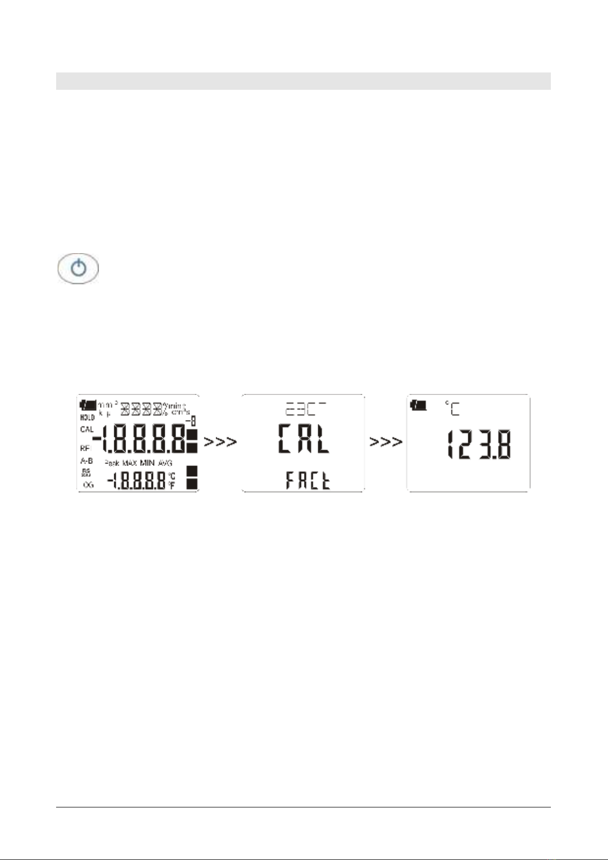
2 . St a r t in g t h e U ser ca libr a t ion pr oce du re: t he "> > > _ CAL_ M ODE" m essage
is displayed in t he com m ent line, and " FACt " is displayed in t he m ain line.
The inst rum ent is pr ovided wit h t he fact or y ( "FACt ") calibr at ion . I t is also
possible t o per form a " USER calibrat ion" (" USEr ")of inst rum ent+ probe. The
calibrat ion inform at ion is saved in t he inst rum ent m em ory and not in t he pr obe.
The sam e correct ion is applied t o any probe connect ed to t he input : t herefore,
the "USER calibrat ion" should only be used wit h t he probe used for calibrat ion
and not with other probes.
•use t he and arrows ( respect ively locat ed abov e t he HOLD and REL
key s) and select USEr, t o access t he " USER calibrat ion" procedur e;
•pr ess DATA/ ENTER t o confir m t he m odificat ion;
•the "SEL_MEAS_1/ 2" m essage is displayed in the com m ent line;
•use t he and arrows ( respect ively locat ed abov e t he HOLD and REL
keys) t o select "0", "1" or "2" in t he m ain line;
•pr ess DATA/ ENTER t o confir m t he m odificat ion;
•pr ess CLR/ ESC t o cancel t he m odificat ion;
•to ex it t he m enu, press t he UNI T/M EN U key again.

HD2307 - 10 - V1.7
PROBES AN D MEASUREM ENTS
The inst rum ent wor ks w it h t em perat ur e pr obes fit t ed wit h SI CRAM m odule ( w it h a
Platinum Pt100 sensor with 100Ω resistance) or with direct 4 wire Pt100, 3 wire
Pt 100, or 2 wire Pt 1000 sensor. The excit at ion current was chosen in or der t o
m inim ize the sensor self-heat ing effect s.
The SI CRAM m odule act s as an interface bet ween t he sensor on t he probe and the
inst rum ent . There is a m icroprocessor circuit w it h a perm anent m em ory inside the
m odule t hat enables t he inst rum ent t o recognize t he t ype of probe connected and t o
read it s calibrat ion inform at ion.
The probes w it h SI CRAM m odule are aut om at ically det ect ed, while t he direct probes
m ust be set up in t he Pr obe t y pe m enu it em ( please see chapt er ‘The program m ing
m enu’) .
The probe is det ect ed durin g turn on, and t his ca nnot be per form ed w hen the
instr um ent is alr eady on, t her efore if a probe is connect ed and the
instr um ent is on , it is necessary t o t urn it off a nd on.
TEM PERATURE MEASU REM EN T
I n all versions the t em perat ure sensor is housed in t he end part of t he probe.
The response tim e for t he m easurem ent of the tem perat ure in air is great ly reduced if
t he air is m oving. I f t he air is st ill, st ir t he probe. The response t im es are longer t han
t hose for liquid m easurem ent s.
The t em perat ure m easurem ent by im m e rsion is carried out by inserting the probe in
the liquid for at least 60 m m ; t he sensor is housed in t he end part of the probe.
I n t he tem perat ure m easurem ent by pe n et ra t ion t he probe t ip m ust be insert ed t o a
depth of at least 60 m m , the sensor is housed in the end part of t he probe.
N OTE: when m easuring t he t em perat ure on frozen blocks it is convenient t o use a
m echanical t ool to bore a cavit y in which to insert t he t ip probe.
I n order to perform a correct con t a ct m easurem ent, the m easurem ent surface m ust
be even and sm oot h, and the probe m ust be perpendicular to the measurem ent plane.
So a s t o obt ain t h e cor r ect m e asur em e nt , t he in se rt ion of a dr op of oil or
h ea t -conduct ive pa st e betw een the sur face and the pr obe is usefu l ( do n ot
use w ater or solvents) . This m et hod also im proves t he respon se tim e.
The ° C or ° F unit of m easurem ent can be chosen using the UNI T/ MENU key.
CALI BRATI ON OF TH E PROBE
To calibrat e t he probes correct ly, a knowledge of and abiding by the physical
phenom ena on which t he m easurem ent is based is fundam ent al: t his is t he reason
why it is recom m ended to abide by what is reported below carefully, and only t o
perform new calibr at ions if t echnically pr oficient and using t he suit able equipm ent .
The sensor is ca libr at e d in t he fa ct ory an d the Calle nda r V an Duse n
par am et er s a re r ecorde d in t h e SI CRAM m odu le. The probes with direct input

HD2307 - 11 - V1.7
a re ch eck e d for con for m it y w it h class A t ole ra n ce according to norm I EC751 -
BS1904 - DI N43760.
The inst rum ent is provided wit h t he FACT ( fact ory) calibr at ion.
The user is also able to perform a USER ca lib ra t ion of inst rum ent + probe.
The calibrat ion inform at ion is saved in t he instrum ent m em ory and not in the probe.
The sam e correct ion is applied t o any probe connect ed t o t he input : t herefore, the
"USER calibrat ion" should only be used wit h t he probe used for calibrat ion and not
with other probes.
To pass from t he user to t he factory calibration and back, proceed as follows:
•press sim ult aneously UN I T/ M EN U and DATA/ EN TER to open the m enu:
•press ENTER until t he m enu it em "CAL_ MODE" is select ed.
•use t he and arr ow s ( r espect ively locat ed abov e t he HOLD and REL keys) t o
select t he t ype of calibrat ion;
•confirm by pressing D ATA/ EN TER.
CALI BRATI ON SEQUEN CE –IN STRUM EN T ON LI N E W I TH TH E PRO BE(S) :
The calibrat ion can be carried out on one or t wo points t h a t sh ou ld diffe r by a t
le ast 1 0 ° C and be included in the probe funct ioning range.
1. I nsert the probe int o a t herm ost at ic bat h, the t em perat ure of which is precisely
known from a reading taken on a sam ple reference therm ometer. Wait for t he
m easurem ent to st abilize.
2. Press cont em por ar ily U N I T/ M EN U and DATA/ EN TER.
3. Press D ATA/ EN TER.
4. Use t he and ar row s ( respect ively locat ed abov e t he HOLD and REL key s) t o
select t he USER calibr at ion;
5. Confir m w it h D ATA/ EN TER.
6. The "SEL_ M EAS_ 1 / 2 " m essage is displayed in t he com m ent line.
7. Use t he and arrows to select " 1 " ( fir st calibrat ion point ) .
8. Confirm with DATA/ EN TER.
9. The "UP DOW N 1 st M EAS" m essage is displayed in t he com m ent line: t he
inst rum ent display shows t he m easured t em per at ure.
10.Use the and ar row s t o cor rect t he indicat ed value unt il it coincides wit h t he
value m easured by t he sam ple r eference t herm om et er.
11.Confirm wit h DATA/ EN TER.
12.To exit t he procedure without perform ing the second point, select "0 " and press
EN TER.
13.To calibr at e t he second point , select t he point " 2 " using t he and arrows.
14.Press D ATA/ EN TER.
15.The " UP DOW N 2 nd M EAS" m essage is displayed in t he com m ent line.
16.Move t he probe to t he second t herm ost at ic bat h and wait for t he m easurem ent t o
stabilize.
17.The inst rum ent display shows the m easured t em perat ure.
18.Use the and ar row s t o cor rect t he indicat ed value unt il it coincides wit h t he
value m easured by t he sam ple r eference t herm om et er.
19.Confirm wit h DATA/ EN TER.
20.To exit t he procedure, select " 0 " using the and arrows and press EN TER.
The procedure is now com plet e.
HD2307 - 12 - V1.7
CON N ECTI N G TH E TP4 7 CON N ECTOR FOR TH E 3AN D 4W I RE PT1 0 0 AN D 2OR 4 -
W I RE PT1000 PROBES:
Where pr esent , ex tend t he t elescopic rod t o t he necessary lengt h pay ing at tent ion t o
the cable so that All probes produced by Delta OHM are provided wit h a connect or.
The Plat inum Therm om et er Model H D2 3 0 7 .0 also work wit h direct 3 and 4-w ire
Pt 100 and 2 or 4-wire Pt1000 probes m anufact ured by ot her producers; for t he
inst rum ent connect ion is prescr ibed t he TP4 7 connect or to which the probe's wires
should be welded.
The inst ruct ions t o connect t he Plat inum pr obe t o t he TP47 m odule are pr ov ided
below.
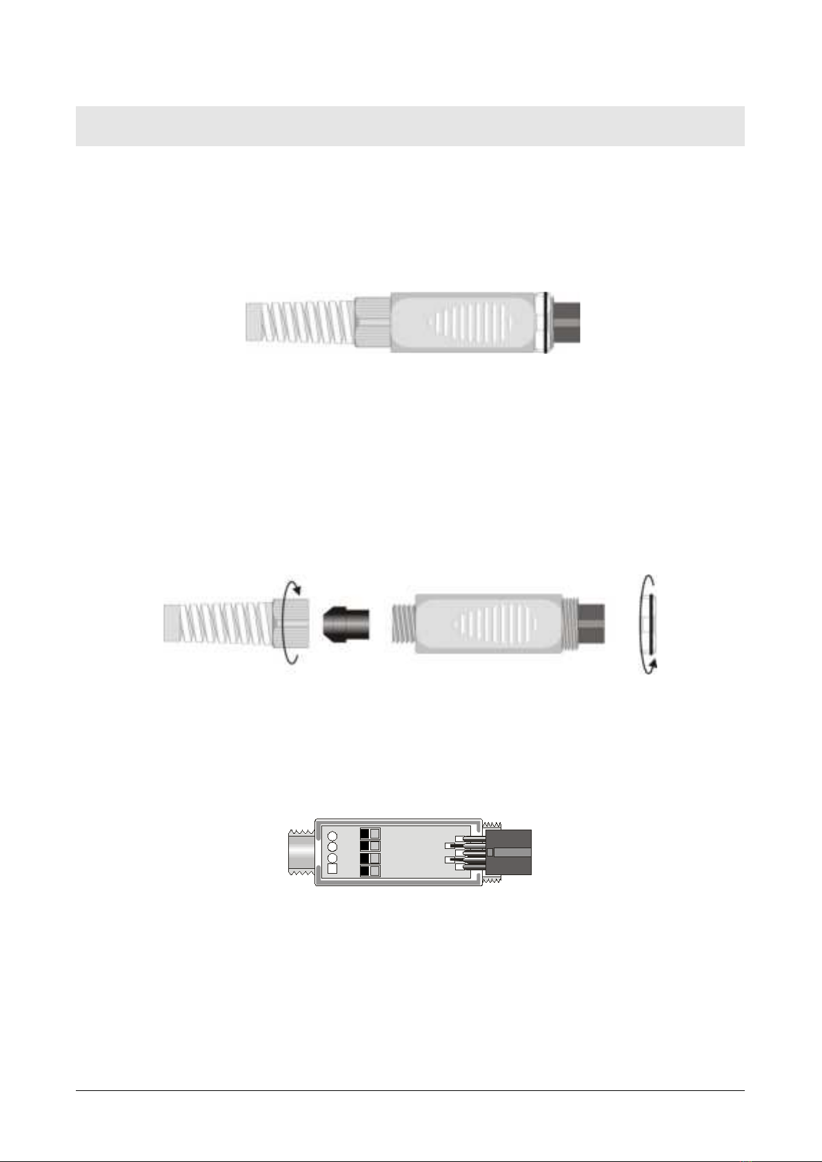
The TP4 7 m odule is supplied com plet e w it h fair lead and gasket for 5 m m m ax im um
diam et er cables.
Do t he following t o open t he m odule and connect a probe:
1. unscrew the fairlead;
2. ext ract t he gasket;
3. rem ove t he label using a cut ter;
4. unscrew t he r ing on t he opposit e side as illust rat ed in t he figur e:
5. open t he two m odule shells: t he print ed circuit t o which t he probe m ust be
connect ed is housed inside. On t he left there are the 1…4 points on which the
sensor wires must be welded. The JP1…JP4 j um pers are in t he center of t he board.
These m ust be closed wit h a t in bead for som e t ype of sensors:
1
2
3
4
Pt100 3 wires
Pt1000
Ni1000
Not Used
Ca u t ion ! Before welding, pass the probe cable through t he fairlead and gasket.
HD2307 - 13 - V1.7
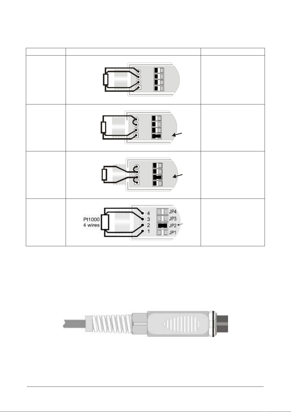
6. Weld the w ires as shown in t he t able:
Sensor
TP4 7 Boa r d con ne ct ion
Jum p er t o close
Pt 100 4
wires
4JP4
3JP3
1JP1
2 JP2
Pt100
4 wires
None
Pt 100 3
wires
4JP4
3JP3
1JP1
2 JP2
Pt100
3
wires
JP1
Pt 1000 2
wires
JP4
4
JP3
3
JP1
1
JP22
Pt1000
2
wires
JP2
Pt 1000 4
wires
JP2
Ensure t he welds are clean and perfect .
7. Once t he welding operation is com plete, close t he t wo shells;
8. I nsert the gask et in t he m odule;
9. Screw the fairlead and the ring.
10.At the ot her end of the m odule, enter t he ring w it h t he O-Ring as indicat ed in t he
pict ure.
11.Make sure t he cable is not t wist ed while you are screwing the fairlead. Now t he
probe is ready.
HD2307 - 14 - V1.7
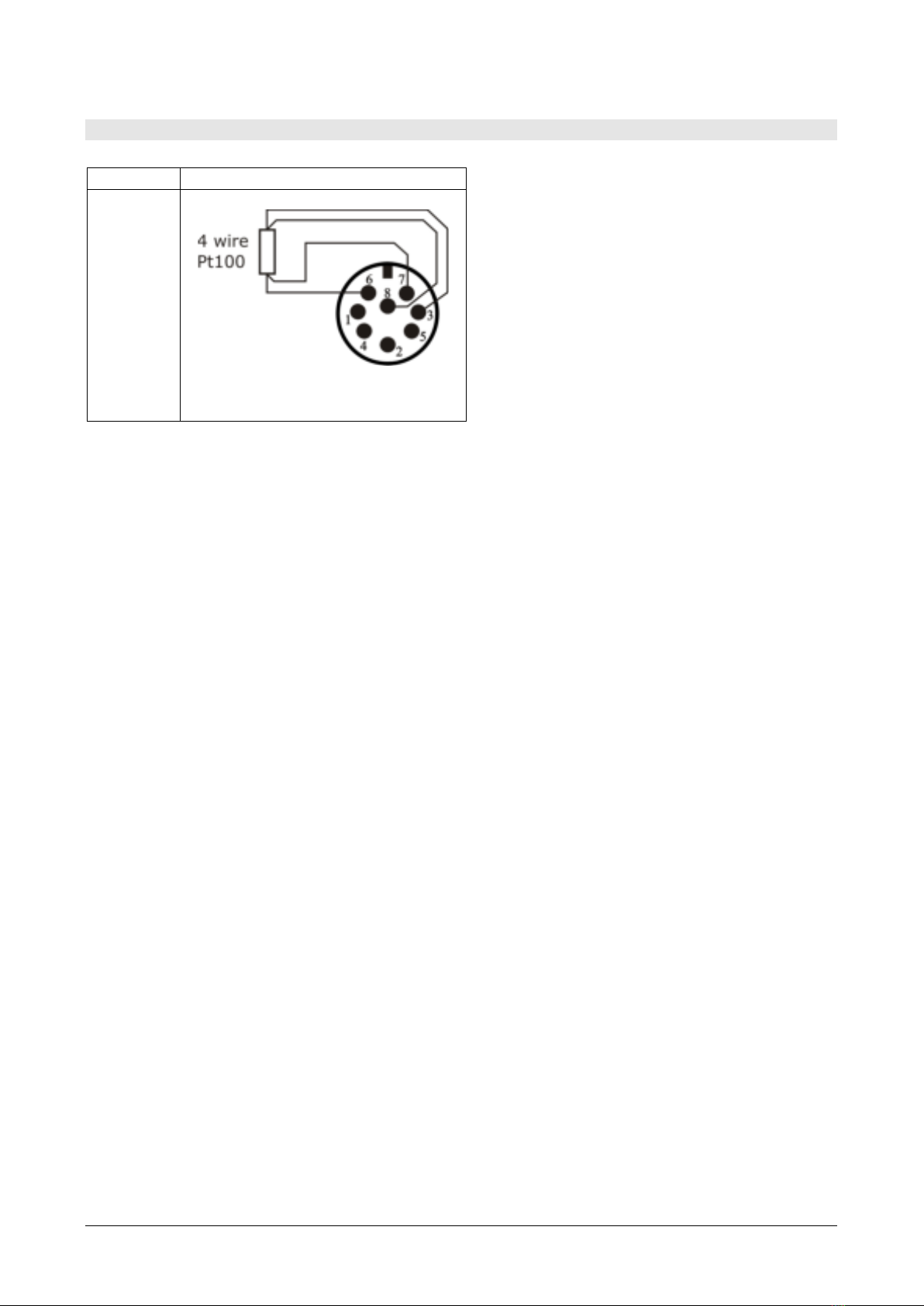
DIRECT CONNECTION OF 4WIRE PT100 SENSORS
4 w ir e Pt 1 0 0 se nsors can be soldered
dir ect ly t o t he pin s of t he fly ing fem ale
connect or wit hout m aking use of t he
TP47 board. The 4 wires of t he Pt 100
sensors have t o be soldered as
indicat ed in the figure on the left. I n
order t o use t his t y pe of pr obe it is
necessary t o set up t he m enu it em
“ Probe Type” .
The P100 probe is recognized upon
t urning on t he inst rum ent : connect the
probe when t he inst rum ent is sw it ched
off and then t urn it on.
Sensor
Direct soldering to the connector
Pt100 4
wires
View of the soldering side
of the flying female connector

HD2307 - 15 - V1.7
W ARN I N GS AN D OPERATI N G I N STRUCTI ON S
1. Do not expose t he probes t o gases or liquids that could corrode the m at erial of t he
sensor or t he probe itself. Clean t he probe carefully after each m easurem ent.
2. Do not bend the probe connectors or force them upward or downward.
3. Do not bend or for ce t he cont act s when insert ing t he probe connect or int o t he
inst rum ent .
4. Do not bend, deform or drop t he probes, as t his could cause irreparable dam age.
5. Always select t he m ost suitable probe for y our applicat ion.
6. Do not use t he tem perat ure probes in presence of corrosive gases or liquids. The
sensor cont ainer is m ade of AI SI 316 st ainless st eel, while t he cont act probe
container is m ade from AI SI 316 st ainless st eel plus silver. Avoid cont act bet ween
t he probe surface and any st icky surface or product t hat could corrode or dam age
it .
7. Above 400° C and below –40° C, av oid v iolent blows or t her m al shock s t o Plat inum
tem perat ure probes as t his could cause irreparable dam age.
8. To obt ain reliable m easurem ent s, t em perat ure var iat ions t hat are too rapid m ust
be avoided.
9. Tem perat ure probes for surface m easurem ents ( cont act pr obes) m ust be held
perpendicular against t he surface. Apply oil or heat -conduct ive past e bet ween t he
surface and t he pr obe in or der t o im prov e cont act and r educe r eading t im e.
What ever you do, do not use wat er or solvent for t his purpose. A contact
m easurem ent is always very hard t o perform . I t has high levels of uncert ainty and
depends on t he ability of t he operat or.
10.Tem perature m easurem ent s on non-m et al surfaces usually require a great deal of
t im e due t o t he low heat conduct ivity of non-m etal m aterials.
11.The sensor is not insulat ed from it s ext ernal casing; be very careful not t o com e
int o cont act w it h liv e par ts ( above 48V) . This could be ex trem ely
dangerous for the inst rum ent as w ell as for t he operat or , who could be
elect rocuted.
12.Avoid t aking m easurem ent s in presence of high frequency sources, m icrow ave
ovens or large m agnet ic fields; result s m ay not be very reliable.
13.Clean the probe carefully after use.
14.The inst rum ent is wat er resist ant and I P67, but should not be im m ersed in wat er.
The probe connect ors m ust be fit ted wit h sealing gasket s. Should t he inst rum ent
fall int o t he w at er , check for any w at er infilt rat ion. Gent ly handle t he inst rum ent in
such a way as to prevent any water infiltrat ion from t he connect ors' side.

HD2307 - 16 - V1.7
I N STRUM EN T SI GN ALS AN D FAULTS
The following t able list s all er ror indicat ions and inform at ion displayed by t he
inst rum ent and supplied to the user in different operat ing sit uations:
D isp la y in dica t ions
Ex pla n a t ion
> > > CAL_ M OD E
Calibrat ion m ode
RTD _ PRBE_ TYPE
Type of probe connect ed
1 ST_ MEAS UP D OW N
Correct the first point using t he arrows
/
2 N D_ M EAS UP DOW N
Correct t he second point using the arrows
/
BATT TOO LOW
CH N G N O W
Indication of insufficient batt ery charge appearing on turning on.
Th e inst r um ent issu es a long beep an d t urns off. Replace t h e
bat t er ies.
CAL
LOST
Pr og ram er ror : it ap pear s aft er t u rn in g on for a few seconds.
Contact t he inst rum ent 's supplier.
CAL FACT
Fact ory calibration
CAL USER
User calibration
ERR
This appears if t he pr obe has alr eady been det ect ed by t he
instrum ent, but is disconnect ed. At t he sam e t im e an
int erm it tent beep is issued.
FUN C CLRD
Max, m in and average v alues cleared
NEW PROBE DET This m essage appears when a probe is inserted int o a funct ioning
instrum ent . Turn t he inst rum ent off and then back on again.
N O_ PRBE_ SER_ N UM
The connect ed p robe' s ser ial num ber is absent
OVER or UN DR
Measu rem ent ov erflow : indicat es t hat t he prob e is m easuring
a value ex ceeding the m easuring range.
PLS_ EX I T > > > FU N C
RES_ FOR_ FACT ON LY
Please exit using ESC > > > funct ion reserv ed t o fact ory
calibration
PRBE_ SER # # # # # # # #
Serial num ber # # # # # # # # of t he connect ed probe
PROB
ERR
A pr ob e w it h SI CRAM m odu le has been insert ed w hen not
adm issible for t hat specific in st rum ent .
PROB COM M LOST
This appear s if t h e prob e has alr eady been d et ect ed by t he
inst rum ent, but is disconnect ed. At t he sam e t im e an
int erm it tent beep is issued.
SEL MEAS 1 / 2
Select m easurem ent 1 or 2
SYS
ERR
#
I nst rum ent m anagem ent program er ror. Con t act t he
inst rum ent 's supplier and com m unicat e t he num eric code #
repor t ed by t h e display .
I N STRUM EN T STORAGE
I nst rum ent st or age condit ions:
•Tem perat ure: -25…+ 65° C.
•Hum idit y: less than 90% RH wit hout condensation.
•Do not st ore t he instrum ent in places where:
•hum idity is high;
•the inst rum ent m ay be exposed to direct sunlight;
•t he inst rum ent m ay be exposed t o a source of high t em perat ure;
•the inst rum ent m ay be exposed to strong vibrat ions;
•t he inst rum ent m ay be exposed t o st eam , salt or any corr osive gas.
The inst rum ent case is m ade of ABS plast ic: do not use any incom pat ible solvent for
cleaning.
HD2307 - 17 - V1.7
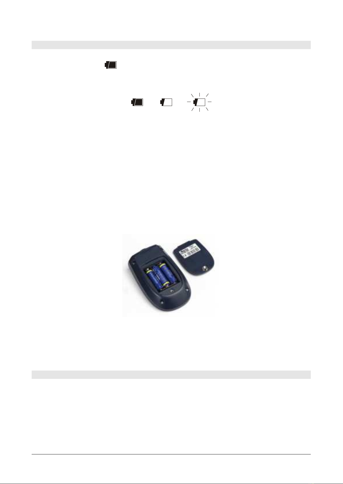
LOW BATTERY W ARN I N G AN D BATTERY REPLACEM EN T
The bat tery sym bol
on t he display const antly shows the bat tery charge st atus. To t he ext ent that bat t er ies
have dischar ged, the sym bol "em pt ies" . When t he charge decreases st ill further it
start s blinking.
I n t his case, bat teries should be replaced as soon as possible.
I f you continue to use it, the inst rum ent can no longer ensure correct m easurem ent.
The m em ory dat a are m aint ained.
I f t h e ba t t er y ch ar ge lev el is insu fficien t , t h e f ollow ing m e ssa ge a ppe ar s
w h en you t urn the inst rum ent on:
BATT TOO LOW
CH N G N OW
The inst rum en t issues a lon g beep and tu rns off. I n this case, repla ce the
ba t t er ie s in or de r t o t urn the instrum ent back on .
To replace t he bat teries, proceed as follows:
1. swit ch t he inst rum ent off;
2. unscrew t he battery cover counter clockwise;
3. replace t he bat t er ies ( 3 1.5V alkaline bat t er ies - t ype AA) ;
4. screw the cover on clockwise.
M alfu nct ion ing upon turning on aft er bat tery replacem en t
Aft er replacing t he bat teries, t he inst rum ent m ay not rest art correct ly; in t his case,
repeat t he operation.
Aft er disconnect ing t he bat teries, wait a few m inut es in order t o allow circuit
condensers to dischar ge com pletely; then reinsert t he bat teries.
WARN I N G ABOU T BAT TERY USE
•Bat teries should be rem oved when the inst rum ent is not used for an ext ended
t im e.
•Flat batt er ies m ust be replaced im m ediat ely.
•Avoid bat teries leaking.
•Always use good qualit y leakproof alkaline bat teries. Som et im es on t he m arket ,
it is possible t o find new bat teries w it h an insufficient charge capacity.

HD2307 - 18 - V1.7
N OTES ABOUT W ORKI N G AN D OPERATI VE SAFETY
Au t hor iz e d u se
The t echnical specifications as given in chapter TECHNI CAL CHARACTERI STI CS m ust
be observed. Only t he operat ion and running of the m easuring inst rum ent according
t o t he inst ruct ions given in t his operat ing m anual is aut hor ized. Any ot her use is
considered unauthorized.
Ge ne r al sa fe t y inst r uct ions
This m easuring system is const ructed and t est ed in com pliance wit h t he EN 61010-1
safety regulat ions for elect ronic m easuring inst rum ent s. I t left t he fact ory in a safe
and secure technical condit ion.
The sm oot h funct ioning and operat ional safet y of the m easuring syst em can only be
guaranteed if t he generally applicable safet y m easures and t he specific safet y
inst ruct ions in t his operat ing m anual are followed dur ing oper at ion.
The sm oot h funct ioning and operat ional safet y of t he inst r um ent can only be
guaranteed under t he envir onm ent al and elect r ical operat ing condit ions t hat ar e in
specified in chapt er TECHNI CAL CHARACTERI STI CS.
Do not use or store t he product in places such as list ed below:
•Rapid changes in am bient tem perat ure which m ay cause condensat ion.
•Corrosive or inflam m able gases.
•Dir ect v ibrat ion or shock t o t he inst rum ent .
•Excessive induct ion noise, st at ic elect r icit y, m agnet ic fields or noise.
I f the m easuring sy st em was t ransport ed from a cold envir onm ent t o a w arm
environm ent , t he form at ion of condensat e can im pair t he funct ioning of t he m easurin g
syst em . I n t his event , wait unt il t he t em perat ure of the m easuring syst em reaches
room t em perature before putt ing t he m easuring system back int o operat ion.
Obligat ions of t he purcha ser
The purchaser of t his m easuring syst em m ust ensure t hat t he follow ing laws and
guidelines are observed when using dangerous subst ances:
EEC direct iv es for prot ect iv e labour legislat ion
Nat ional pr ot ect iv e labour leg islat ion
Safet y regulat ions

HD2307 - 19 - V1.7
I N STRUM EN T TECH NI CAL CH ARACTERI STI CS
TECH NI CAL I N FORM ATI ON ON TH E RTD TH ERM OM ETER
I nst rum ent
Dim ensions ( Length x Widt h x Height ) 140 x 88 x 38 m m
Weight 160 g ( com plet e wit h bat t er ies)
Mat erial ABS
Display 2x4½ digit s plus sym bols
Visible area: 52 x 42 m m
Operat ing condit ions
Operat ing tem perat ur e - 5…+ 50° C
Warehouse t em perat ure - 25…+ 65° C
Working r elat ive hum idit y 0…90% RH w it hout condensat ion
Pr ot ect ion de gr ee I P6 7
Power
Bat teries 3 1.5V t ype AA bat t eries
Aut onom y 200 hours wit h 1800m Ah alkaline
bat teries
Power absorbed wit h inst rum ent off < 20 µA
Connect ions
I nput for probes 8- pole m ale DI N45326 connector
Unit of Measurem ent ° C - ° F;
Measurem ent of t em perat ure by I nst rum ent
Pt 100 m easurem ent range - 200…+ 650° C
Pt 1000 m easurem ent range - 200…+ 650° C
Resolution 0.1° C
Accuracy ±0.05° C
Drift after 1 year 0.1° C/ year
HD2307 - 20 - V1.7
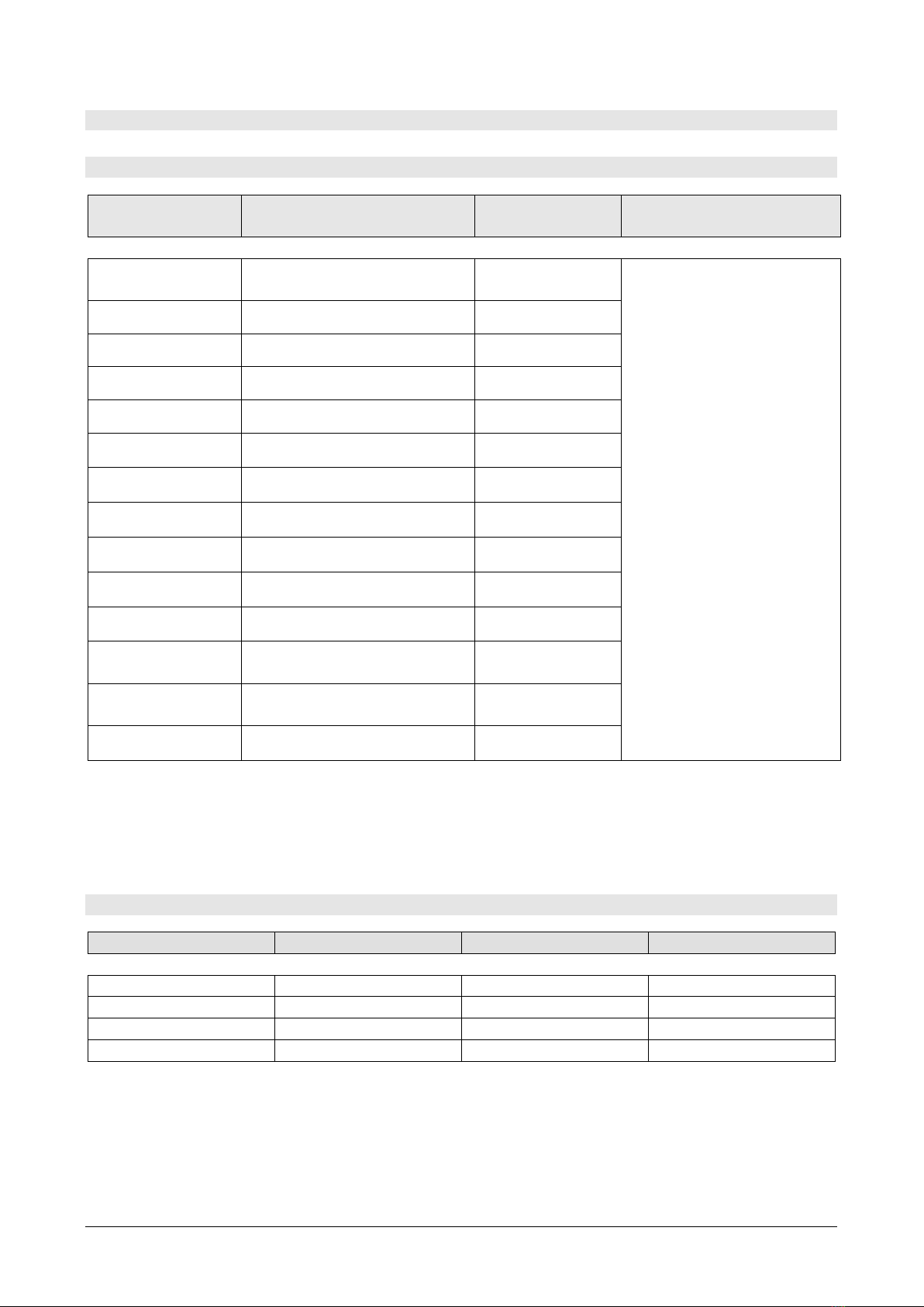
TECH NI CAL D ATA OF PROBES AN D M ODULES I N LI NE W I TH TH E I N STRUMEN T
TEM PERATURE PROBES PT100 SEN SOR USI N G SI CRAM MODULE
Model Type
Applica t ion
range
Accu ra cy
TP4 7 2 I I m m ersion
-
196° C…+ 500° C
± 0.1° C ( @ 0 ° C)
± 0.2° C ( -50 °C ≤ t ≤
250 ° C)
± 0.3° C ( t < -50 ° C; t
> 250 ° C)
TP4 7 2 I .O I m m ersion - 50° C…+ 300° C
TP4 7 3 P.I Penet rat ion - 50° C…+ 400° C
TP4 7 3 P.O Penet rat ion - 50° C…+ 300° C
TP4 7 4 C.O Contact - 50° C…+ 300° C
TP4 7 5 A.O Air - 50° C…+ 250° C
TP4 7 2 I .5 I m m ersion - 50° C…+ 400° C
TP4 7 2 I .1 0 I m m ersion - 50° C…+ 400° C
TP4 9 A.I I m m ersion - 70° C…+ 250° C
TP4 9 AC.I Contact - 70° C…+ 250° C
TP4 9 AP.I Penet rat ion - 70° C…+ 250° C
TP8 7 5 .I
Globe-t herm om et er
Ø 150 m m
-30° C…+ 120° C
TP8 7 6 .I
Globe-t herm om et er
Ø 50 m m
-30° C…+ 120° C
TP8 7 .O I m m ersion - 50° C…+ 200° C
Com m on characterist ics
Re solut ion 0 .0 1 ° C in t he range ± 1 9 9 .9 9 ° C,
0 .1 ° C in t h e r em a ining f ie ld
Tem perat ure drift @ 20° C 0.003% / ° C
Pt 1 0 0 / Pt1 0 0 0 pr obes w it h TP4 7 con ne ct or w it h ou t SI CRAM m odule
Model
Type
Applica t ion r a nge
Accu ra cy
TP4 7 .1 0 0 .O
Pt 100 4 wires
-50…+ 250° C
Class A
TP4 7 .1 0 0 0 .O
Pt 1000 4 w ires
-50…+ 250° C
Class A
TP8 7 .1 0 0 .O
Pt 100 4 wires
-50…+ 200° C
Class A
TP8 7 .1 0 0 0 .O
Pt 1000 4 w ires
-50…+ 200° C
Class A
Com m on characterist ics
Re solut ion 0 .0 1 ° C in t he range ± 1 9 9 .9 9 ° C,
0 .1 ° C in t h e r em a ining f ie ld
Tem perat ure drift @ 20° C Pt 100 0.003% / ° C
Pt 1000 0.005% / ° C
Table of contents
Other Delta OHM Thermometer manuals

Delta OHM
Delta OHM HD2107.1 User manual

Delta OHM
Delta OHM HD 9212 User manual

Delta OHM
Delta OHM HD3406.2 User manual

Delta OHM
Delta OHM HD2205.2 User manual

Delta OHM
Delta OHM HD2328 User manual

Delta OHM
Delta OHM HD2108.1 User manual

Delta OHM
Delta OHM HD2304.0 User manual

Delta OHM
Delta OHM HD2178.1 User manual

Delta OHM
Delta OHM HD2127.1 User manual


